Abstract: With the advent and rapid evolution of fifth-generation mobile communication technology (5G), electronic devices, notably smartphones and tablets, are increasingly gravitating towards high performance, integration, and miniaturization. Consequently, they generate exceedingly high heat flux densities in extremely confined spaces. Vapor chambers, known for their efficient heat transfer capabilities characterized by low thermal resistance and temperature uniformity, find extensive application in heat dissipation modules for devices with high heat flux densities.
This paper provides an overview of the current research status of vapor chambers, detailing their advantages, heat transfer principles, and structures. It also examines the current state of modeling and simulation of vapor chambers, analyzes the impact of fabrication processes on vapor chamber performance, and proposes methods for preparing micro-nano scale copper-based liquid absorption cores, along with reliability evaluation techniques for vapor chambers. Finally, the paper discusses the application prospects and development trends of vapor chambers.
The advancement of the electronics industry has propelled electronic products towards smaller sizes and higher integration levels, resulting in increasingly high power consumption of electronic components. For instance, dissipative estimates for gap amplifiers in military and aerospace applications exceed 1000W/cm2.
Conventional heat sinks are no longer adequate to meet the cooling demands of high heat flux densities. Among passive cooling devices, capillary-driven heat sinks, such as heat pipes, flat heat pipes, and vapor chambers, have been proven to be the most effective .
Vapor chambers, in particular, are renowned for their superior heat conduction, excellent temperature uniformity, and versatile structural adaptability, making them a focal point of research for scholars worldwide.
1. Introduction to vapor chamber
1.1 Advantages of Vapor Chambers
Currently, electronic devices primarily utilize various cooling methods, including graphite cooling, graphene cooling, thermal conductive gel cooling, heat pipe cooling, and vapor chamber cooling. Graphite cooling, graphene cooling, and thermal conductive gel cooling rely on heat dissipation materials, offering limited cooling effects suitable for small electronic products. Conversely, heat pipe and vapor chamber cooling employ heat dissipation devices, boasting high cooling efficiency and primarily applied in medium to large electronic devices.
While both heat pipes and vapor chambers utilize phase change for heat dissipation, encompassing conduction, evaporation, convection, and condensation, they differ in heat conduction methods. Heat pipes exhibit one-dimensional heat conduction, whereas vapor chambers display two-dimensional heat conduction, resulting in larger contact areas with the heat dissipation medium, ensuring more uniform cooling and better catering to the demands of miniaturized electronic devices in the era of 5G. Research indicates that vapor chamber coolers outperform heat pipes by 20% to 30% in terms of performance, further enhancing heat conduction efficiency.
1.2 Principles and Structure of Vapor Chambers
Vapor chambers consist of a sealed shell, a porous liquid absorption core, and a working fluid. The liquid working fluid evaporates and absorbs heat at the evaporation end, then transports in a gaseous form within the cavity to the condensation end, where it releases heat and condenses. The condensed liquid working fluid is then re-transported to the evaporation end through the capillary action of the porous liquid absorption core. This cycle allows vapor chambers to operate independently without external power, ensuring efficient heat conduction.
Vapor chambers can be categorized into two types based on heat transfer direction: those transferring heat along thickness and length directions. Moreover, vapor chambers are classified based on thickness into standard vapor chambers (≥2mm), ultra-thin vapor chambers (<2mm), and extremely thin vapor chambers (≤0.6mm).
To facilitate the cyclic operation of vapor chambers, the maximum pressure of the capillary must exceed the total pressure of the vapor chamber.
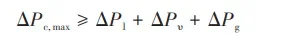
In the formula, ΔP1 represents the pressure drop of the working fluid returning from the condensation end to the evaporation end, ΔPu denotes the pressure drop from the evaporation end to the condensation end, and ΔPg accounts for the pressure drop due to gravity. The maximum capillary pressure, ΔPc,max, can be evaluated using the following formula.
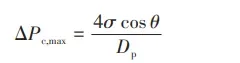
In the equation,σ represents the liquid surface tension coefficient,θ denotes the contact angle between the liquid working fluid and the solid wall surface, and Dp is the effective pore diameter of the liquid absorption core.
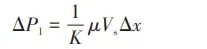
In the equation, K stands for the equivalent heat transfer length of the vapor chamber, μ represents the dynamic viscosity coefficient of the liquid, Vs is the liquid surface velocity, and Δx is the distance between the condensation end and the evaporation end.
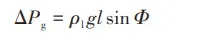
In the equation, ρl represents the liquid density, g is the acceleration due to gravity, l is the thickness of the vapor chamber, and Φ is the angle between the vapor chamber and the horizontal line. When Φ > 0, it indicates that the evaporation end of the vapor chamber is lower than the condensation end, facilitating the reflux of the liquid working fluid due to the effect of gravity. Conversely, when Φ < 0, it signifies that the evaporation end of the vapor chamber is higher than the condensation end, hindering the return flow of the working fluid from the condensation end to the evaporation end due to the effect of gravity.
2. Vapor Chamber Simulation
Over the past two decades, numerous scholars have conducted theoretical modeling, simulation analysis, and numerical simulations of vapor chambers. They have investigated factors such as working fluid materials, filling ratios, the structural design of liquid absorption cores, and the inclination angle of vapor chambers, and their effects on heat transfer performance.
Currently, commonly used simulation analysis software includes Fluent, Flotherm, and Comsol Multiphysics. While these software tools facilitate modeling and evaluation of vapor chamber heat transfer performance, accurately solving complex liquid absorption characteristics remains challenging.
To simplify the phase change transport process within vapor chambers, the structure and transport process of vapor chambers are often approximated as a two-dimensional model. The liquid absorption core structure is characterized by a porous capillary structure, which simplifies the process and possesses generality but may introduce certain errors.
For instance, using Comsol Multiphysics software, the porosity of the vapor chamber can be extracted using post-processing tools through the use of the software’s creeping flow interface. The permeability can then be calculated using Darcy’s law to evaluate the liquid absorption performance of the liquid absorption core.
By solving the fluid flow problem of the porous liquid absorption core using the Brinkman equation interface, solving the laminar flow problem in the vapor cavity using the laminar flow interface, and solving the heat transfer problems of all shapes, tube walls, liquid absorption cores, and vapor cavities using the porous medium heat transfer interface, the heat transfer performance of vapor chambers can be assessed.
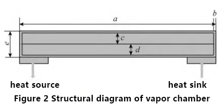
This paper presents the simulation and design of a vapor chamber, with specific dimensions as shown in Figure 2, where a=60mm, b=0.1mm, c=1.4mm, d=1.4mm, and e=3mm. A heating power of 5W is applied, and water cooling is chosen as the heat sink with a heat transfer coefficient of 2600W/(m2·K).
The vapor chamber shell is made of copper, with water vapor set as the upper-layer material and a porous material set as the lower-layer material. The solid material is copper, and the working fluid material is deionized water.
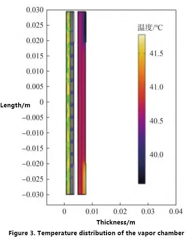
The simulated temperature distribution of the vapor chamber is shown in Figure 3. From Figure 3, it can be observed that the maximum temperature difference between the heating end and the cooling end is approximately 2.5°C. According to the heat resistance calculation formula (5), the heat resistance is calculated to be 0.5°C/W.
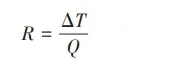
In the equation, R represents thermal resistance, Q denotes heat transfer power, and ΔT signifies temperature difference.
3. Vapor Chamber Manufacturing Process
3.1 Shell
The selection of shell materials depends on several factors, including compatibility (with the working medium and external environment), strength-to-weight ratio, thermal conductivity, porosity, processability, and machining properties.
Copper, aluminum, stainless steel, titanium alloy, and other metals are the most common shell materials. Among them, copper is widely used in industrial electronic equipment cooling due to its good ductility and relatively higher thermal conductivity. Copper exhibits lower thermal resistance in the vapor cavity between 0 and 200°C, making it suitable for ground equipment cooling.
Aluminum, on the other hand, is preferred in space applications due to its weight advantage.
In recent years, with the rapid development of flexible electronic devices, the demand for flexible vapor chambers has increased. Polymer materials have gradually become a research focus for the shell materials of flexible ultra-thin vapor chambers.
3.2 Liquid Absorption Core
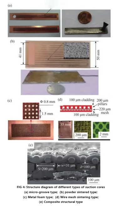
Traditional vapor chamber liquid absorption core structures include micro-groove type, powder sintering type, foam metal type, wire mesh sintering type, and composite structure type. Figure 4 illustrates these five different liquid absorption core structures. However, these structural forms have inherent limitations that restrict the optimization and improvement of vapor chamber heat transfer performance.
For example, the low porosity of sintered liquid absorption cores affects liquid transport capacity, copper mesh liquid absorption cores exhibit poor thermal conductivity, channel structure liquid absorption cores have limited capillary suction capacity, foam metal liquid absorption cores have large and unevenly distributed pores and lower mechanical performance, and composite structure liquid absorption cores combine the advantages of multiple liquid absorption core structures but have complex processing and limited space, which restrict their application and development in extremely thin vapor chambers.
3.3 Working Fluid Materials
Common working fluid materials used in liquid absorption cores include water, methanol, ethanol, methane, n-pentane, HFE7100, propylene glycol, and regenerated agent 141b. Due to the incompatibility between working fluid materials and liquid absorption materials, chemical reactions or physical changes may occur, resulting in the generation of non-condensable gases inside the vapor chamber. When non-condensable gases begin to accumulate in the vapor chamber, especially in the condenser section, the vapor chamber gradually becomes blocked, causing a decrease in the thermal properties of the working fluid, corrosion dissolution of the shell material, and ultimately leading to a decline in vapor chamber performance or even vapor chamber failure. Shukla et al. studied the compatibility of commonly used materials, as shown in Table 3.
3.4 Vapor Chamber Related Processes
The encapsulation, working fluid injection, degassing, vacuum pumping, performance testing, and other processes of standard vapor chambers and most ultra-thin vapor chambers are relatively mature. These processes have corresponding equipment. The encapsulation process mainly uses diffusion welding, brazing, and laser welding.
However, for ultra-thin and flexible vapor chambers, problems such as collapse and rupture are prone to occur during the encapsulation process. Although some research suggests that the reliability of encapsulation can be improved through optimization of processes and materials, these methods are still in the exploratory stage and have not yet formed a complete and reliable full-process technology.
The manufacturing of shell plates and support pillars for standard vapor chambers mainly uses mechanical processing methods. However, with the gradual reduction in vapor chamber thickness, this method is difficult to meet the processing accuracy requirements.
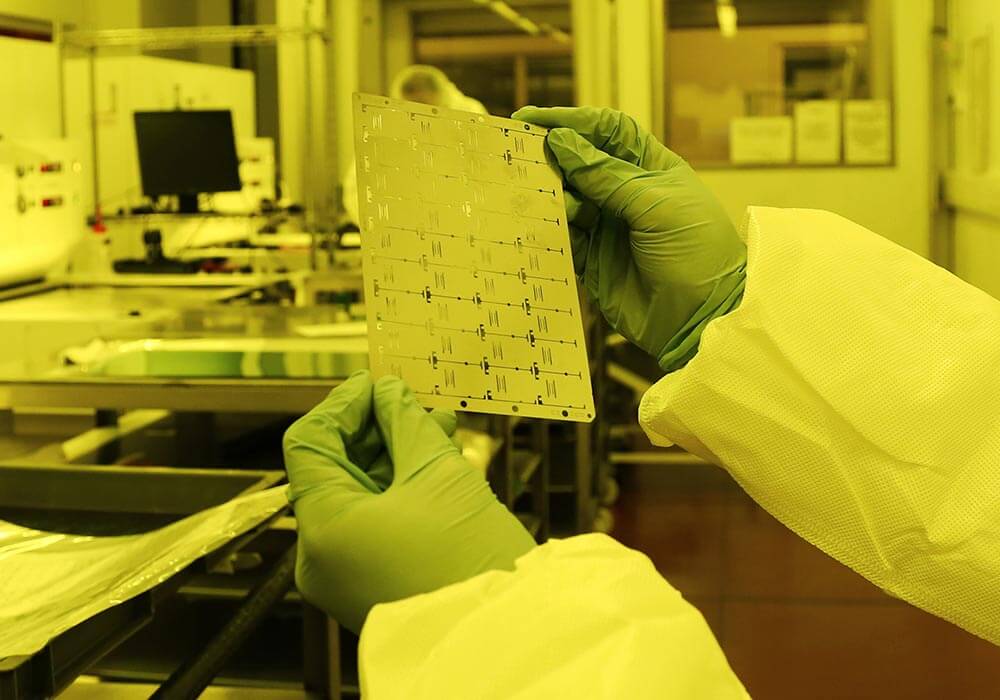
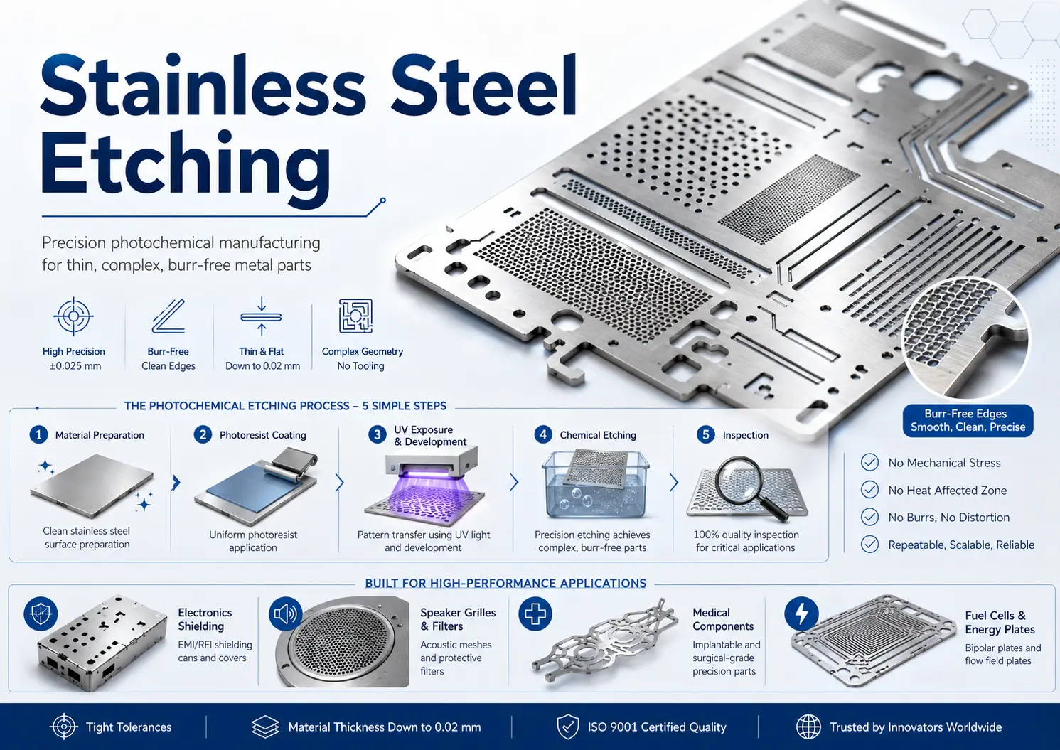
Currently, chemical etching technology is mainly used for the manufacturing of ultra-thin vapor chamber shell plates and support pillars. This technology is applied in the manufacturing of large-sized vapor chambers and requires further research and exploration.
4. Heat Transfer Plate Performance
4.1 Performance Evaluation
4.1.1 Liquid Absorption Performance
The liquid absorption capacity of the absorption core is primarily determined by the permeability rate K and capillary pressure ΔPcap, which are related as shown in Equation (6):
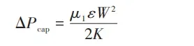
Here, μ1 represents the dynamic viscosity of the working fluid, ϵ is the porosity, and W is the capillary coefficient, which can be measured and calculated. The permeability rate K and porosity ϵ of different absorption core structures vary. The permeability rate and porosity can be directly measured using mature instruments like the Porolux200 capillary flow porometer, or by constructing a testing platform, or through direct calculation methods. For instance, for wire mesh cores, the permeability rate K and porosity ϵ can be calculated using Equation (7):
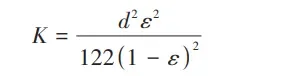
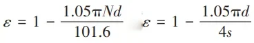
N represents the mesh count, d is the wire diameter, and s is the wire spacing. Other types of absorption cores, such as sintered powder cores, slotted cover network cores, annular cores, and parallel circular tube cores, can also be calculated using empirical formulas.
The heat transfer Q that a vapor chamber can transfer is related to the mass flow rate of the working fluid that the absorption core can transport. Q can be expressed as Equation (8):
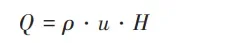
ρ is the density of the working fluid, u is the volumetric flow rate of the working fluid, and H is the latent heat of vaporization. u can be expressed as Equation (9):
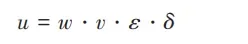
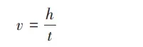
w is the width of the liquid absorption, v is the average velocity of the fluid ascent, ϵ is the porosity of the absorption core, and δ is the thickness of the absorption core. v can be expressed ℎ represents the ascent height within a unit time t. as Equation (10):
Hence, the performance of the absorption core can be evaluated by experimentally testing the ascent height, allowing for comparison and selection of structures with superior liquid absorption performance for prototyping and encapsulation. Currently, there are generally three methods for testing:
1. Weighing Method: This method involves measuring the weight gain of the absorption core due to liquid absorption. However, it cannot obtain data for curved surfaces, leading to relatively large errors.
2. Optical Measurement Method: Optical methods involve using light to measure the ascent height of the liquid. However, this method may not be suitable for absorption cores with darker colors.
3. Infrared Measurement Method: Infrared methods utilize infrared technology to measure the ascent height of the liquid. This method can provide accurate measurements regardless of the color of the absorption core.
Each method has its advantages and limitations, and the choice of method depends on the specific characteristics of the absorption core being tested.
4.1.2 Heat Transfer Performance
The testing principles of the heat transfer performance testing platform for vapor chambers involve evaluating performance indicators such as thermal resistance, uniformity of temperature, and equivalent thermal conductivity. The expression for thermal resistance is shown in Equation (5).
The expression for temperature uniformity is given in Equation (11):
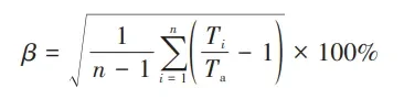
β represents temperature uniformity, n is the number of temperature measurement points, Ta is the average temperature of the heat source, and Ti is the temperature at the i measurement point.
The expression for equivalent thermal conductivity is given in Equation (12):
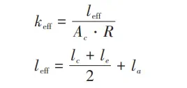
keff represents the equivalent thermal conductivity,leff is the equivalent length, le, lc, and la are the lengths of the evaporator section, condensation end, and adiabatic end of the vapor chamber, respectively, Ac is the cross-sectional area of the vapor chamber, and R is the thermal resistance.
The derivation and expression of the maximum power limit are relatively complex and are usually determined based on experimental phenomena. During experiments, as the heating power is continuously increased, there may be sudden increases in thermal resistance. The corresponding power at this point is considered the maximum power limit. Alternatively, if the vapor chamber cannot reach a steady state with increased input power or if the maximum temperature difference at each measurement point exceeds 10°C, then the power at this operating state is considered the maximum power limit.
4.1.3 Reliability Performance
Currently, there is no comprehensive evaluation method for the lifespan and reliability of vapor chambers. In the industry, the reliability of vapor chambers is mainly assessed based on the experience with heat pipes, using accelerated stress aging tests.
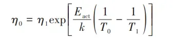
Firstly, based on the operating conditions of the vapor chamber, accelerated conditions such as temperature, vibration, humidity, etc., can be selected. The thermal resistance of the vapor chamber is tested using thermal performance testing equipment until there is a inflection point in the thermal resistance value, indicating the extreme operating condition of the vapor chamber. The temperature at this point is considered the limit temperature, denoted as T. Secondly, aging test conditions are selected. To ensure rapid estimation of the lifespan and reliability of the vapor chamber, the maximum stress is chosen as T1, and another relatively smaller stress is chosen as T2.
When conducting accelerated stress aging tests, the model for estimating lifespan is shown in Equation (13):
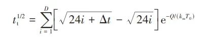
tt is the accelerated lifespan of the vapor chamber, i is the hour of testing, D is the duration of high-temperature aging of the vapor chamber, Δt is the testing time, Q is the thermal load power, km is the thermal conductivity, T0 is the average operating temperature, and n is the number of vapor chambers teste
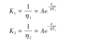
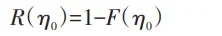
To estimate the lifespan under accelerated conditions and calculate the failure probability F, the accelerated lifespans corresponding to the two stress conditions η1 and η2 are determined.
The calculation of the activation energy factor is mainly based on Equation (14):
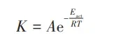
K is the reciprocal of the lifespan, A is a constant, R is the Boltzmann constant, T is the operating temperature, and Eact is the activation energy. The two operating temperatures are then calculated using Equation (15):
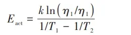
The activation energy can then be calculated as shown in Equation (16).
The estimation of lifespan under normal or operating conditions (T0) is obtained by deriving the Arrhenius equation, resulting in Equation (17).
The reliability can then be expressed as shown in Equation (18).
4.2 Factors Influencing Performance
Several factors influence the performance of vapor chambers, including their orientation, heat source, heat sink, thickness, wick structure, and fill ratio.
1) Effect of Vapor Chamber Orientation:
The orientation of the vapor chamber during operation significantly affects its performance. Ma et al. studied the variation of thermal resistance of vapor chambers at angles ranging from 0° to 50° (in intervals of 10°). They found that the overall thermal conductivity did not change significantly with angle variation, with a maximum thermal resistance of 0.5 K/W. Tsai et al. observed through experiments that thermal resistance decreased with increasing heat input. At a vertical orientation of 90°, the maximum thermal resistance was found to be 0.893°C/W. Due to the significant influence of gravity on fluid flow between the condenser and evaporator sides, thermal resistance increases with the angle of inclination. Therefore, it’s preferable to use vapor chambers in favorable orientations to maximize their performance.
2) Impact of Heat Sources:
The arrangement of heat sources on the vapor chamber significantly affects its overall heat dissipation performance. In different application scenarios, vapor chambers may have multiple heat dissipation points (uniform and non-uniform heating) or heat dissipation modules. Therefore, many researchers have conducted extensive experiments and simulations to explore the impact of uniform and non-uniform distribution of heat sources on the heat transfer performance of vapor chambers.
Experimental results from the application of vapor chambers in the LED (Light Emitting Diode) field indicate that under a 30W input power, vapor chambers exhibit better heat dissipation performance compared to copper and aluminum plates, with a thermal resistance reduction of at least 34%.
Experimental studies on the thermal performance of calculator processing units showed that the thermal resistance under high thermal loads is higher than that under low operating thermal loads. Additionally, research suggests that high heat at the evaporator end can lead to absorption and boiling limits, resulting in explosions or boiling during startup at low temperatures and high heat input. It’s evident that both the heat source and the temperature at the evaporator end collectively influence the performance of vapor chambers.
3) Influence of Heat Sink:
In the application of vapor chambers, enhancing heat dissipation performance can be achieved by increasing the heat transfer area. This method involves connecting the heat sink to an external cooling system and uniformly transferring heat to the substrate to prevent local overheating, thereby improving heat dissipation performance. This can be achieved by modifying the geometric parameters of air-cooled and water-cooled condenser heat sinks, such as width, height, and quantity, to enhance the overall performance of the vapor chamber.
4) Impact of Wick Structure:
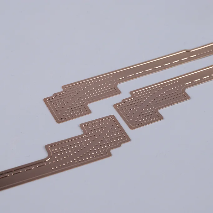
The geometric shape and structure of the wick determine parameters such as porosity, pore size, permeability, specific surface area, thermal conductivity, and surface wettability. Optimizing the wick structure to improve permeability, capillary pressure, and liquid absorption capacity can enhance the performance of the vapor chamber. The main methods for producing wick structures include sintering, machining, etching, and micro/nano-scale fabrication. Sintering is primarily used to produce porous wick structures such as powder, foam metals, and wire mesh. Machining is commonly employed for machining micro-groove wick structures. Etching can process small-sized wick structures. Micro/nano-scale fabrication techniques, including electro-deposition and 3D printing, can fabricate precise micro-scale structures for wicks, improving surface wettability and enhancing capillary performance.
5) Influence of Vapor Chamber Thickness:
The thickness affects the steam flow resistance and thermal performance of the vapor chamber. Thicker vapor chambers exhibit lower thermal resistance. Relatively thin vapor chambers lead to higher surface temperatures and increased thermal resistance. Additionally, smaller vapor chambers result in higher flow resistance, leading to increased thermal resistance. Therefore, developing extremely thin vapor chambers requires higher demands.
6) Impact of Working Fluid Filling Ratio:
The filling ratio refers to the percentage of working fluid volume occupying the total internal volume of the system. In a 0% filling ratio mode, where no working fluid is present, the vapor chamber operates in a pure conductive mode. In a 100% filling ratio mode, the vapor chamber system behaves as a single-phase heat pipe. A low filling ratio may lead to dry-out, while a high filling ratio can reduce the gas phase space inside the chamber, hindering bubble release and weakening steam flow. The specific filling ratio needs to be optimized through experimental studies.
Dry-out limits and critical heat flux define the upper limit conditions for the safe operation of the vapor chamber. Apart from these factors, selecting appropriate working fluids, materials, and operating temperatures for different application scenarios and environments can effectively enhance the performance of the vapor chamber.
5. Prospects for Vapor Chamber Applications
1)5G Base Stations:
Vapor chambers are primarily used for the single-point and shell heat dissipation of 5G base station BBU (Indoor Baseband Processing Unit) and AAU (Active Antenna Unit). Currently, there is a significant increase in demand for AAU heat dissipation. The semi-solid-state die-cast + vapor chamber (targeting large size, high power) heat dissipation solution is expected to become mainstream. BBU heat dissipation is mainly divided into three parts: front, back, and internal chip heat dissipation. With the increasing demand for vapor chamber performance in 5G base stations, there is a need to develop vapor chambers with higher heat dissipation performance to meet the high-density heat dissipation requirements of macro and small base stations.
2)Smartphones, Computers, and Other Electronic Products:
The diversification and high-performance requirements of electronic products such as smartphones and laptops have led to increasingly higher overall energy consumption. In recent years, most smartphones and laptops released by domestic manufacturers have adopted vapor chamber heat dissipation solutions. With the continuous development of 5G smartphones and tablet PCs towards high power, thinness, and high performance, ultra-thin, high-quality, and high-end vapor chambers are expected to become the mainstream trend in the future.
3)High-Power LED Lighting:
With the increase in LED chip power consumption and changes in the structure of high-power LED lamps (lightweight and easy to install), traditional heat dissipation methods have become inadequate. Vapor chambers, as a new solution to the heat dissipation problem of LED light sources, gradually become the main demand and industry trend in the era of high-power LEDs, thanks to their unique heat dissipation advantages. Currently, vapor chambers have been applied in the automotive headlight field, including Mercedes-Benz, BMW, and Mais Lighting companies. While there is ongoing research on the application of vapor chambers in LED work and floodlights, large-scale applications have not yet been realized. With the increasing demand for vapor chambers in the low- to mid-end LED market, reducing the application cost of vapor chambers will become an important research direction.
4) Thermal Management in New Energy Vehicles:
The rapid development of the new energy vehicle industry has made thermal management of the power source—power batteries, a key technology. Generally, vapor chambers are used at the interface between the cooler and the power battery for heat dissipation. The uniform and efficient heat conduction performance of vapor chambers can effectively reduce battery heat, improve battery stability and reliability. However, widespread practical applications have not yet been achieved.
5) High-Power Lasers:
The electrical-optical conversion efficiency of high-power lasers is mostly between 40% to 60%, with nearly half of the energy being dissipated in the form of heat. Meanwhile, the heat generated during the operation of lasers can lead to issues such as reduced output power, decreased electrical-optical conversion efficiency, and increased threshold current in semiconductor lasers. Vapor chambers can rapidly and uniformly dissipate the high heat flux density on the heat sink of semiconductor lasers, ensuring stable optical performance while improving heat dissipation efficiency. Currently, this technology is in the laboratory application stage and has not yet been implemented in practical products, mainly due to limitations in the application scenarios and working modes of high-power lasers.
The application of vapor chambers in aerospace environments differs from that on the ground. In aerospace environments, vapor chamber heat dissipation devices must possess characteristics such as lightweight, high performance, and high reliability due to their exposure to harsh and complex conditions including zero gravity, hypergravity, microgravity, vibration, and shock.
However, due to the specificity of their application, there are relatively few standardized vapor chambers available, and limited information can be obtained. For example, EcoMia designed vapor chambers for high-heat-flux aerospace electronic devices, effectively controlling thermal resistance. The company developed vapor chamber modules for high-power microwave amplifiers in a certain satellite payload, achieving an 85% weight reduction.
Additionally, researchers have proposed using vapor chambers based on leaf vein biomimicry for aerospace electronic chip cooling and lightweight vapor chambers for aircraft and rocket engine cooling.
In summary, optimizing the design of vapor chambers in terms of structure, materials, packaging, and manufacturing processes to enhance the liquid absorption capacity of the wick will be one of the main directions for future vapor chamber applications. This will lead to thinner, lighter, more reliable, and cost-effective high-performance flexible vapor chambers.
Conclusion:
Managing the heat generated by electronic components within increasingly compact volumes poses a significant challenge for further technological development. Compared to traditional heat pipes, vapor chambers, as a novel heat conduction device, directly contact the heat source and evenly distribute heat in all directions, offering efficient and uniform heat conduction performance. They find widespread applications in electronics, aerospace, new energy vehicles, and other fields.
As the market penetration rate of vapor chambers continues to increase, the industry’s development prospects are promising. Future research efforts will primarily focus on theoretical studies of extremely thin vapor chambers, high-performance wick structure design, and reliable packaging processes. Against the backdrop of electronic products evolving towards higher power, lighter weight, and superior performance, achieving ultra-thin, high-quality, and high-end vapor chambers will emerge as the mainstream trend in the industry.
The data in the article is sourced from the internet. If there are any issues, please feel free to contact us for modification or removal.