As technology continues to advance and international policies drive progress, new energy vehicles are becoming increasingly popular, including hybrid cars, all-electric vehicles, and even hydrogen fuel cell vehicles, which, while not yet common, are slowly gaining attention. If you’re unfamiliar with hydrogen fuel cell vehicles, the following introduction will help you understand them better.
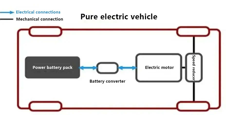
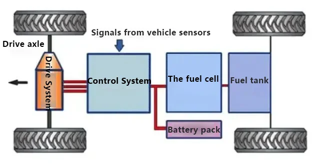
Let’s first take a look at the basic structure diagrams of traditional cars, all-electric cars, and hydrogen energy cars.
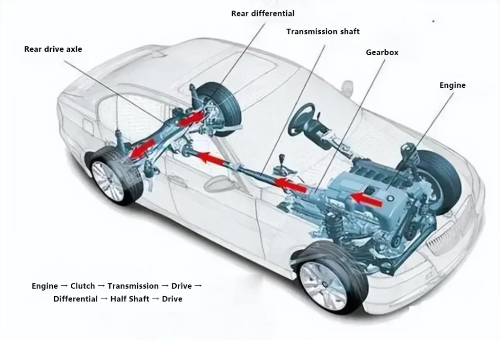
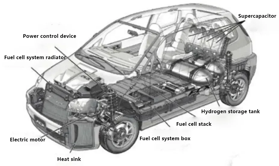
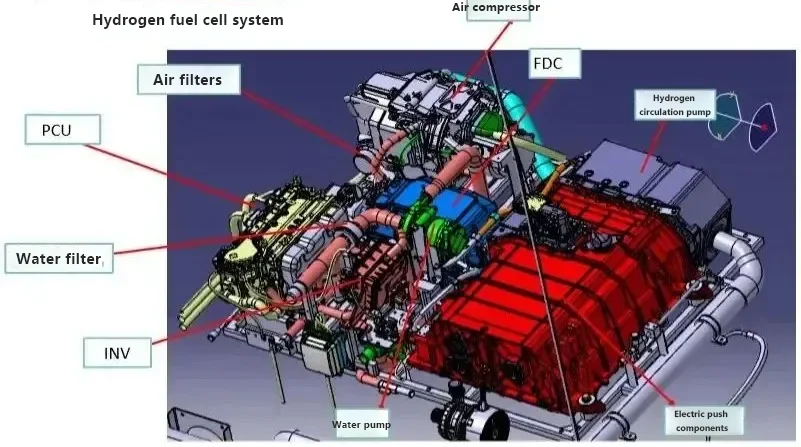
The structure of hydrogen fuel cell vehicles consists of: primarily composed of a hydrogen fuel cell stack, a fuel cell boost converter, a hydrogen supply system, a power battery pack, a drive motor, and a power control unit, among others.
Working principle of hydrogen fuel cell vehicles:
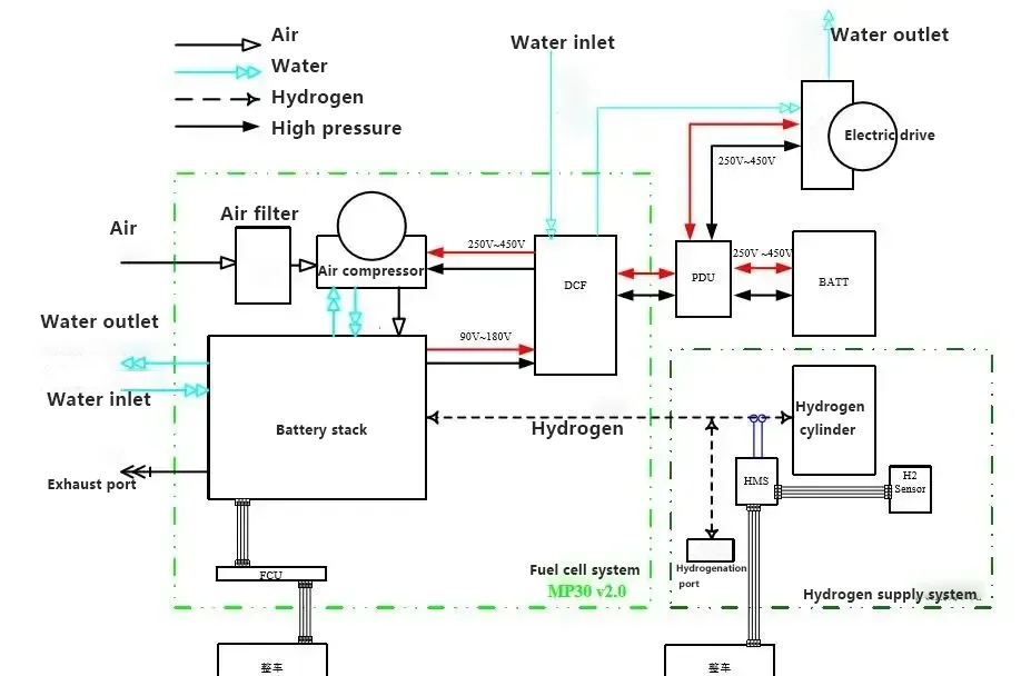
1. Electrochemical Reaction: Oxygen from the air and hydrogen from high-pressure storage tanks undergo an electrochemical reaction in the fuel cell stack, where a catalyst generates electrical energy.
2. Voltage Boost and Distribution* The electrical energy is sent to the DCF (boost converter) to increase the voltage and reduce the current. The boosted electrical energy is then transferred to the PDU (high-voltage distribution box), which allocates power to the drive motor.
3. Vehicle Propulsion: The drive motor converts electrical energy into mechanical energy to propel the vehicle forward.
4. Energy Storage and Conversion: The BMS (Battery Management System) stores energy in the power battery. The DC/DC and DC/AC converters step down the high voltage for use in various low-voltage DC/AC electrical systems throughout the vehicle.
Below is an explanation of the working principles of the main components in hydrogen fuel cell vehicles:
Hydrogen Fuel Cell: In the fuel cell stack, a chemical reaction occurs between hydrogen and oxygen, leading to the transfer of electric charge and thereby generating electric current. At the same time, the chemical reaction between hydrogen and oxygen produces water as a byproduct, which is then discharged. This is one of the reasons why hydrogen fuel cell vehicles are considered more environmentally friendly.
The fuel cell stack functions as a chemical reaction chamber, with its most critical technology being the “proton exchange membrane.” On either side of this membrane are catalyst layers, where hydrogen is decomposed into charged ions. Since hydrogen molecules are small, the electron-carrying hydrogen can pass through the tiny pores in the membrane to the other side. However, as the electron-carrying hydrogen crosses through the membrane’s pores, the electrons are stripped from the molecule, leaving only positively charged hydrogen protons to pass through the membrane to the other side.
The hydrogen protons are attracted to the membrane’s opposite electrode, where they combine with oxygen molecules. The electrode plates on either side of the membrane break down hydrogen into positively charged hydrogen ions and electrons, while oxygen is broken down into oxygen atoms to capture electrons and become negatively charged oxygen ions.
The flow of electrons between the electrode plates creates an electric current. This current can be used to drive the vehicle’s electric motors. Meanwhile, two hydrogen ions and one oxygen ion combine to form water, which is the only “waste” product of this reaction. Essentially, the entire process is a form of power generation. As the oxidation reaction continues, the constant electron transfer creates the electric current needed to propel the vehicle.
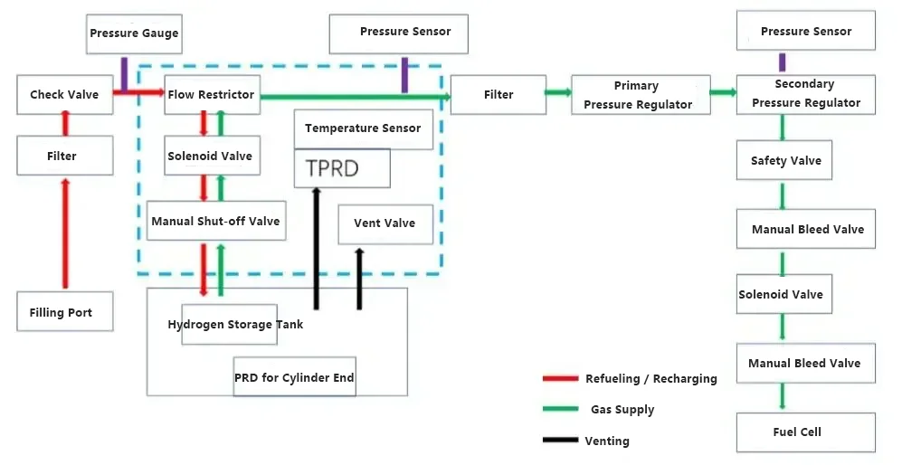
Onboard Hydrogen Supply System: The onboard high-pressure hydrogen supply system is a system designed to provide hydrogen fuel for fuel cell vehicles. It primarily consists of lightweight high-pressure hydrogen storage cylinders, various valves, high-pressure pipelines, a hydrogen refueling port, a safety monitoring system, and a pressure/temperature signal collection system. The process flow diagram is as follows:
Safety Precautions:
1. Temperature Risk: During normal operation, the temperature of the fuel cell system and the coolant supply system can reach around 80 °C, while the temperature of the air supply system can go as high as 150 °C. Therefore, during system operation or shortly after starting, avoid touching any system components or exposed surfaces to prevent burns.
2. High-Pressure Hydrogen: The use of high-pressure hydrogen as a reactant presents a certain level of risk during operation. Before disassembling any pipes or connections, ensure that the high-pressure gas within the system has been depressurized to a safe level. Additionally, hydrogen is a colorless, odorless, and highly flammable gas. While it is non-toxic, it can displace oxygen in the air, potentially causing asphyxiation.
3. High Voltage Risk: Even after the fuel cell system has been shut down, high voltage output may persist for a certain period of time. During this time (at least 5 minutes), there is a risk of electric shock. Repair or other related operations are not allowed until the high voltage has dissipated.