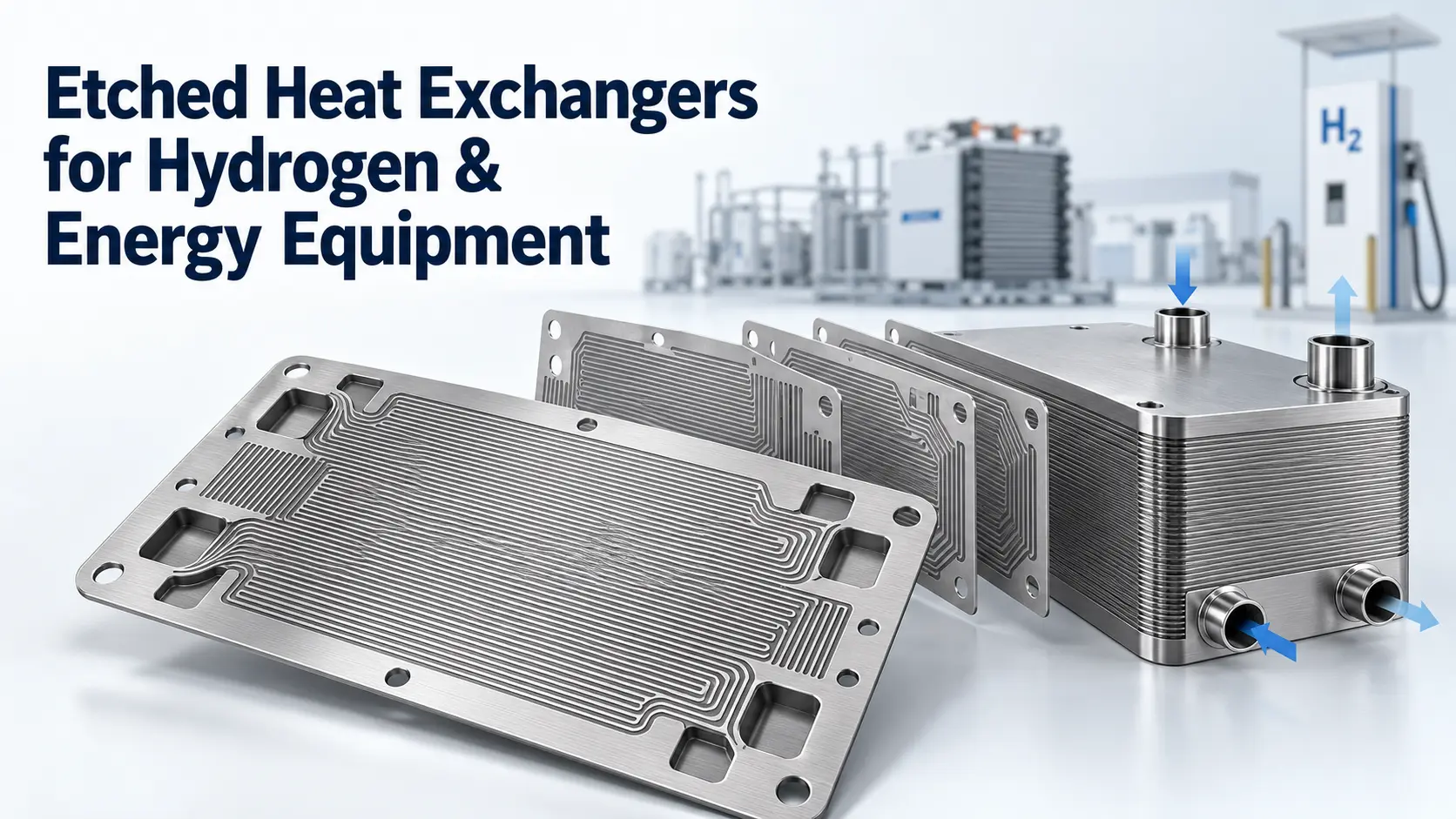

A heat exchanger baffle plate is an internal component used mainly in a shell-and-tube heat exchanger. It redirects shell-side fluid across the tube bundle and usually supports the tubes. Its geometry therefore affects heat transfer, pressure drop, leakage, fouling and flow-induced vibration.
A shell-and-tube baffle differs from a plate heat exchanger’s heat-transfer plate and from a dedicated support or inlet impingement plate. For context, see how a heat exchanger works.
Key Takeaways
- Baffles guide shell-side flow across the tubes and commonly support the tube bundle.
- Greater crossflow can improve shell-side heat transfer, but usually consumes more pressure head.
- Baffle type, cut, spacing, tube-hole clearance and shell clearance must be evaluated together.
- Chemical etching is best suited to thin, flat baffle-like parts with repeated holes or complex two-dimensional patterns.
Definition and Scope
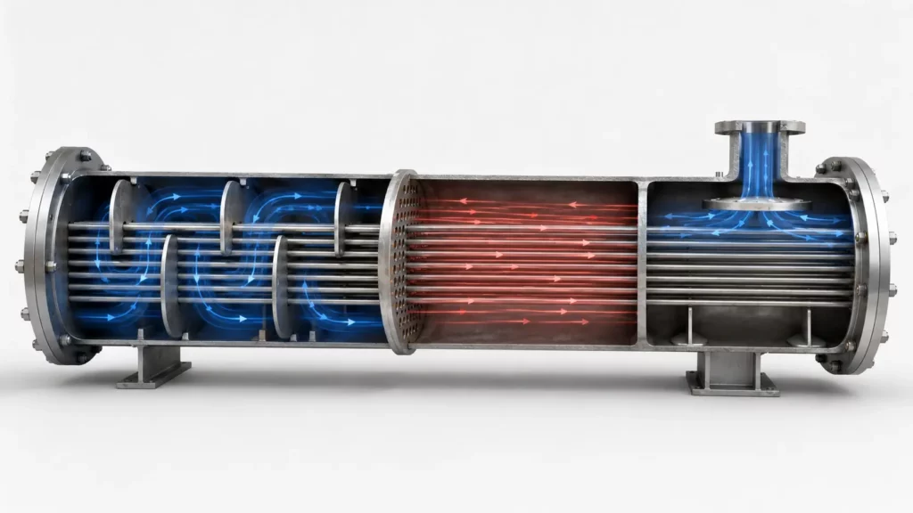
In a conventional shell-and-tube exchanger, transverse baffles are positioned along the tube bundle. Their holes locate or support the tubes. An open region provides the shell-side flow path, while tie rods and spacers maintain the required axial position.
The applicable standard should be identified precisely. The official TEMA support page states that the TEMA Standards, 2026 Edition were issued on 1 August 2026 and became effective immediately. A six-month grace period allows the Eleventh Edition to remain current for work already in process.
TEMA also confirms that the Eleventh Edition was published in 2024 and the Tenth Edition in 2019. Because TEMA has replaced sequential edition numbers with publication years, the 2026 publication should not be described as the “Twelfth Edition.”
The TEMA 2026 Edition summary lists new rules for kettle-shell weir-plate thickness, floating-head retaining rods, removable pass partitions in high-pressure channels, conical-section supports, U-bend-area supports, pass-partition edge thickness and rod baffles. The edition date is therefore an actionable procurement requirement, not merely a reference detail.
Functions of a Baffle Plate
Directing Shell-Side Flow
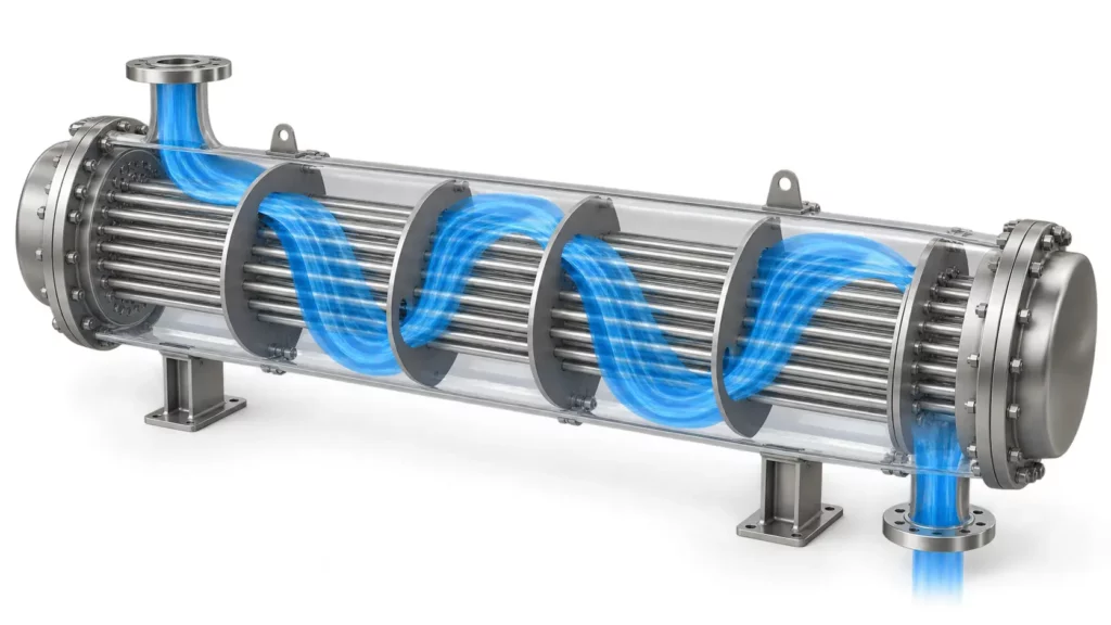
Segmental baffles block part of the shell cross-section. Alternating windows make much of the shell-side stream cross the tube bank repeatedly instead of following the shortest low-resistance route.
The resulting crossflow and mixing can increase the shell-side heat-transfer coefficient. However, every contraction, expansion and change of direction also adds hydraulic resistance. The engineer must therefore balance heat-transfer improvement against the allowable pressure drop.
Baffle layout also affects flow distribution. Poorly controlled shell-side flow can create bypass paths or low-velocity regions. These regions may transfer less heat and may be more vulnerable to deposit accumulation when the fluid has a fouling tendency.
Supporting Tubes and Limiting Vibration Damage
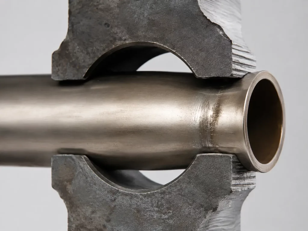
Baffle holes provide intermediate tube support. They reduce unsupported tube length and change the stiffness and vibration response of the tube bundle.
Tube-to-baffle clearance is necessary for manufacturing, assembly and thermal movement. The same clearance, however, permits relative movement when shell-side crossflow excites the tubes.
Repeated impact and sliding at a baffle-hole edge can produce fretting wear, local wall thinning and leakage. Fatigue cracking is another possible damage mode. A peer-reviewed heat-exchanger failure investigation found outside-diameter thinning at multiple baffle locations and concluded that fretting corrosion caused the tube failure.
Longer unsupported spans also change the dynamic response of the tube. A simple span may experience substantial movement near its midpoint, but the actual maximum depends on the vibration mode, support clearance, flow field and boundary conditions.
Baffle spacing and support layout should therefore be included in the flow-induced-vibration assessment. The objective is to control both unsupported length and tube-to-support contact behavior, rather than specifying the smallest possible hole clearance without considering assembly and thermal movement.
Balancing Thermal and Hydraulic Performance
A baffle uses part of the available pressure to create crossflow and mixing. Too little flow control permits leakage and bypass. Too much restriction may increase pumping demand, local velocity and vibration excitation.
This creates a linked design problem. Heat duty, allowable pressure drop, fluid properties, fouling behavior and tube-support requirements must be evaluated together.
Main Baffle Types and Flow Patterns
Several baffle arrangements are used to control shell-side flow. IPIECA’s heat-exchanger guidance identifies segmental, disc-and-doughnut, helical and rod-baffle configurations among the common flow-deflecting arrangements.
| Baffle arrangement | Resulting flow pattern | Typical engineering reason | Primary design issue |
|---|---|---|---|
| Single-segmental | Alternating crossflow | Strong bundle crossflow in a familiar layout | Pressure drop and window-region velocity |
| Double-segmental | Two divided flow paths | Lower velocity per path than a comparable single-segmental design | Distribution and tube support |
| Disc-and-doughnut | Alternating radial flow | Moves fluid between the bundle center and perimeter | Radial distribution and local velocity |
| No-tubes-in-window | Crossflow with empty windows | Supports each tube at every baffle plane | Tube count and bundle arrangement |
| Helical | Rotating shell-side path | Reduces repeated abrupt flow reversals | Forming, assembly and flow continuity |
| Rod baffle | Grid-like tube support | Supports tubes while retaining a relatively open flow area | Rod layout and vibration control |
A single-segmental baffle is a circular plate with one segment removed. Alternating the window position creates a repeated crossflow path.
Double- and triple-segmental designs divide the flow between several openings. They may be considered when pressure drop is limited, although their flow distribution and support layout become more complex.
Disc-and-doughnut systems alternate solid discs and annular plates. This arrangement directs fluid outward and inward through the tube bundle instead of creating a conventional zigzag path.
Helical and rod-baffle systems are structurally different from flat perforated discs. Their three-dimensional form also changes the appropriate manufacturing and assembly methods.
Baffle Plates, Support Plates and Impingement Plates
These components may appear in the same exchanger, but they perform different primary functions.
| Component | Primary function | Typical location | Main flow effect |
|---|---|---|---|
| Transverse baffle plate | Redirect shell flow and support tubes | Repeated along the bundle | Creates shell-side crossflow zones |
| Tube support plate | Reduce unsupported tube length | At selected bundle positions | May redirect little flow |
| Impingement plate | Protect tubes from the inlet jet | Between the shell nozzle and tube bundle | Disperses or deflects incoming flow |
| Longitudinal baffle | Divide shell-side passes | Parallel to the shell axis | Changes the shell-pass arrangement |
| Tube-side pass partition | Divide tube-side flow | Inside the channel or head | Does not control shell-side flow |
The distinction affects process selection. An impingement plate may require greater stiffness and impact resistance because it faces a concentrated inlet stream. A thin flow distributor is more likely to be governed by open area, hole pattern and dimensional accuracy.
A conventional transverse baffle combines flow-control and support functions. A dedicated support plate prioritizes tube stability and may have less influence on the main shell-side flow path.
Key Design Parameters: Cut, Spacing and Clearances
Baffle Cut and Spacing
Baffle cut defines the open segment through which shell-side fluid passes. Changing the cut alters the window area, crossflow area and velocity distribution.
Cut orientation may also affect drainage, venting and the behavior of two-phase fluids. Axial spacing determines how frequently the stream is redirected and how much unsupported tube length remains between adjacent supports.
Reducing the spacing can create more crossflow zones and provide more frequent tube support. It can also raise shell-side pressure drop. The thermal and mechanical effects must therefore be evaluated as one design decision.
Shell-Side Flow Streams and Leakage
The HTRI Stream Analysis Method represents shell-side flow as a combination of crossflow, clearance leakage and bundle bypass:
- Stream A: flow through tube-to-baffle clearances.
- Stream B: the main crossflow through the tube bank.
- Stream C: flow bypassing the bundle perimeter.
- Stream E: leakage between the baffle edge and shell.
- Stream F: bypass through tube-pass-partition lanes.
These streams do not contribute equally to heat transfer or pressure drop. Excessive C and E flow reduces the proportion of fluid crossing the active tube bank. Stream A remains close to the tube surfaces, but it changes the hydraulic distribution.
Baffle-to-shell clearance, bundle-to-shell clearance and tube-to-hole clearance are therefore more than fabrication tolerances. They are thermal-hydraulic design variables.
Sealing strips can be used to restrict selected bypass paths. Their number and position should be included in the exchanger analysis rather than added as an isolated shop-floor modification.
More Baffles: A Quantified Trade-Off
In one numerical study of a specific disc-and-doughnut configuration, increasing the number of baffles produced a reported 17%–29% increase in overall heat-transfer coefficient. Pressure drop increased by approximately 58%–59%.
The 2024 Applied Thermal Engineering study compared segmental, double-segmental, helical, disc-and-doughnut and other configurations using CFD simulations.
These figures should not be converted into a general baffle-count formula. They demonstrate the design trade-off: stronger flow redirection and mixing can improve heat transfer, while hydraulic resistance may rise more quickly under the same conditions.
Engineering note: Published performance figures, baffle cuts and spacing recommendations are screening references. Final geometry, clearances, support layout and inspection criteria require review against the exact exchanger geometry, fluid properties, operating conditions and applicable codes.
Materials and Standards for Baffle Plates
Baffle material must suit the working fluid, design temperature, corrosion or erosion mechanisms, tube material, mechanical support load and manufacturing route.
Carbon steel, stainless steel, titanium and nickel alloys may be selected for different operating environments. The purchasing drawing should specify the exact grade, thickness, corrosion allowance, heat-treatment condition and certificate requirements. A description such as “stainless steel baffle” is not precise enough for production.
For petroleum, petrochemical and natural-gas service, ISO 16812:2019 covers mechanical design, material selection, fabrication, inspection and testing of shell-and-tube heat exchangers. ISO confirmed this edition in 2024.
The complete code hierarchy still depends on the equipment location, operating service and owner specification. TEMA, ISO, API, ASME and project-specific requirements may apply to different parts of the exchanger design.
Manufacturing Options: When Chemical Etching Makes Sense
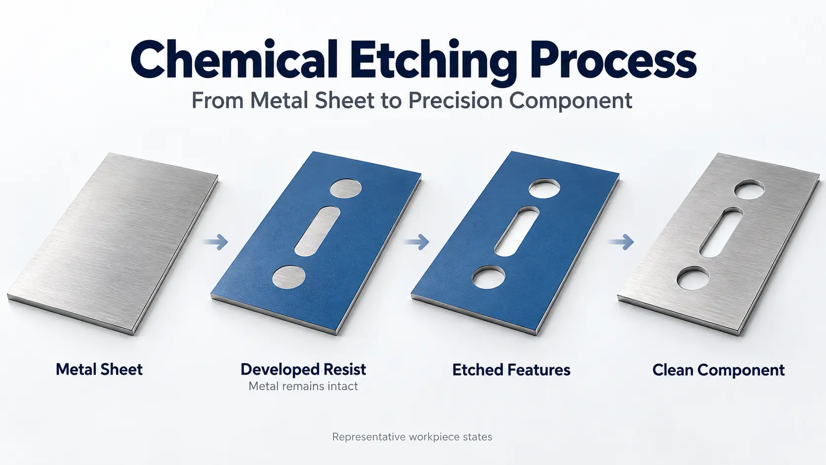
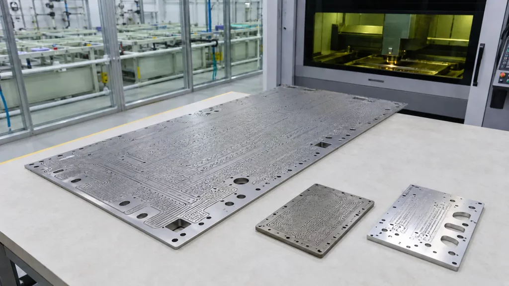
Photochemical etching, also called photochemical machining, uses a photo-defined mask and controlled chemical removal. It can form repeated holes, slots, windows, notches and external profiles without introducing punching burrs.
Chemical removal acts downward and laterally, so the etched edge includes some undercut rather than forming a perfectly cylindrical drilled wall. The relationship between material thickness, minimum hole size, web width, positional accuracy, and edge geometry is therefore central to process selection. These limits should be checked against practical photochemical etching tolerances and design limits before a baffle drawing is finalized.
Chemical etching is best suited to thin, flat baffle-like parts whose main function is flow distribution through a repeated two-dimensional pattern. It is not a replacement for:
- Thick load-bearing support plates
- Formed helical components
- Rod-baffle grids
- Heavily loaded impingement plates
- Parts that require cylindrical drilled holes
- Components dominated by three-dimensional geometry
In these cases, stiffness, impact resistance, hole-wall form or structural loading may be more important than the pattern-production advantages of etching.
A published photochemical machining design guide provides practical starting ratios:
| Geometry screen | Published starting point |
|---|---|
| Minimum hole for stock at or above 0.127 mm | At least 1.1 × material thickness; practical ratios may rise toward 1.8 × for thicker stock |
| Minimum web between dense holes | Approximately 1.2 × material thickness |
| Initial tolerance planning | Approximately ±15% of material thickness |
These figures are preliminary design references rather than guaranteed limits for every material and pattern.
For example, a small tube hole in relatively thick stock is harder to control than a large opening in thin sheet. Difficulty increases further when the design combines high open area, narrow webs and tight positional tolerances.
A baffle manufacturability review should therefore examine hole diameter, pitch, positional tolerance, etched edge profile, flatness and handling stability together.
Related TMNetch Manufacturing Experience
According to a TMNetch project record supplied for this article, one previous flow-plate program combined chemical etching with laser cutting. For large patterned plates or designs that exceed the practical limits of a single process, a combined etching and secondary manufacturing workflow can provide greater flexibility than forcing the entire part through one process.
The largest project format was 600 × 1,400 mm, using stock up to 4 mm. 316 stainless steel and titanium were the materials used most frequently.
For material-specific process information, see TMNetch’s stainless-steel etching capabilities and titanium etching capabilities.
Preparing a Baffle Plate RFQ
A technically useful RFQ should include:
- Baffle function and type
- Drawing number and revision
- Exact alloy, grade and material condition
- Material thickness and certificate requirements
- Outside diameter and baffle cut
- Cut orientation and axial location
- Tube-hole diameter, layout and pitch
- Hole-size and positional tolerances
- Tie-rod holes, drain slots and vent notches
- Flatness, edge profile and surface requirements
- Inspection method and sampling plan
- Prototype quantity and production volume
- Proposed or permitted manufacturing route
- Design temperature and working fluids
- Cleanliness and documentation requirements
- Governing standards and project deviations
Once these requirements are defined, engineers can submit a baffle plate drawing for manufacturability review together with the applicable TEMA edition, material specification, hole geometry, tolerances, operating conditions, and required inspection documentation.
For projects using the latest TEMA requirements, a precise standards line would be:
Applicable standard: TEMA Standards, 2026 Edition; or Eleventh Edition (2024) for qualifying work in process during the stated grace period. Specify Class R, C or B and all project-specific deviations.
TEMA defines Class R for severe petroleum and related processing applications, Class C for commercial and general process applications, and Class B for chemical process service.
The RFQ should also identify any ISO, API, ASME or owner requirements that apply to the complete exchanger.
Frequently Asked Questions
What is the main purpose of a baffle plate in a heat exchanger?
It guides shell-side fluid across the tube bundle and often supports the tubes. These functions influence heat transfer, pressure loss, leakage distribution and vibration response.
How does a baffle plate improve heat transfer?
It creates crossflow and mixing around the tubes. This can increase the shell-side heat-transfer coefficient, although the improvement normally comes with additional pressure loss.
Is a support plate the same as a baffle plate?
No. A transverse baffle normally redirects flow and supports tubes. A support plate is selected mainly to reduce unsupported tube length and may have less influence on the primary flow path.
What is baffle cut?
Baffle cut is the open segment through which shell-side fluid passes. Its size and orientation affect the window area, flow path, local velocity and pressure drop.
Can heat exchanger baffle plates be chemically etched?
Yes, when the part is thin, flat and dominated by two-dimensional holes or flow-distribution features. Material thickness, minimum hole size, web width, flatness and structural function must be reviewed before selecting the process.
Which baffle plates are poor candidates for chemical etching?
Thick structural supports, rod-baffle systems, formed helical elements and heavily loaded impingement plates are generally poor candidates. Their designs depend more on stiffness, impact strength or three-dimensional geometry.
Conclusion
A heat exchanger baffle plate controls shell-side flow while contributing to tube support. Its type, cut, spacing and clearances determine how the exchanger balances heat transfer, pressure drop, bypass flow, fouling and vibration risk.
Chemical etching is a credible manufacturing option for selected thin baffles and flow-distribution plates, especially when they contain dense or complex two-dimensional patterns.
For thin, flat baffle-like parts with repeated holes, slots, or complex two-dimensional patterns, chemical etching can be a practical manufacturing option. Final process selection should still account for structural loading, material thickness, minimum feature size, flatness, inspection requirements, and the governing exchanger standard.