
Photochemical etching is a precision metal manufacturing process. It uses photoresist, ultraviolet light, and controlled chemical etching to remove selected areas from a metal sheet. The process is also called photo etching, photochemical machining, or PCM.
Engineers often use photochemical etching for thin, detailed parts that need clean edges and repeatable features. Typical parts include precision photo-etched metal components, such as metal filters, EMI/RFI shields, lead frames, shims, encoder discs, bipolar plates, and speaker grilles. The process does not use a cutting tool or apply high heat to the metal.
However, achievable tolerance and feature size are not fixed values. They depend on the metal grade, thickness, part geometry, etch depth, surface requirements, and inspection method. A drawing review is therefore essential before production.
Photochemical Etching at a Glance
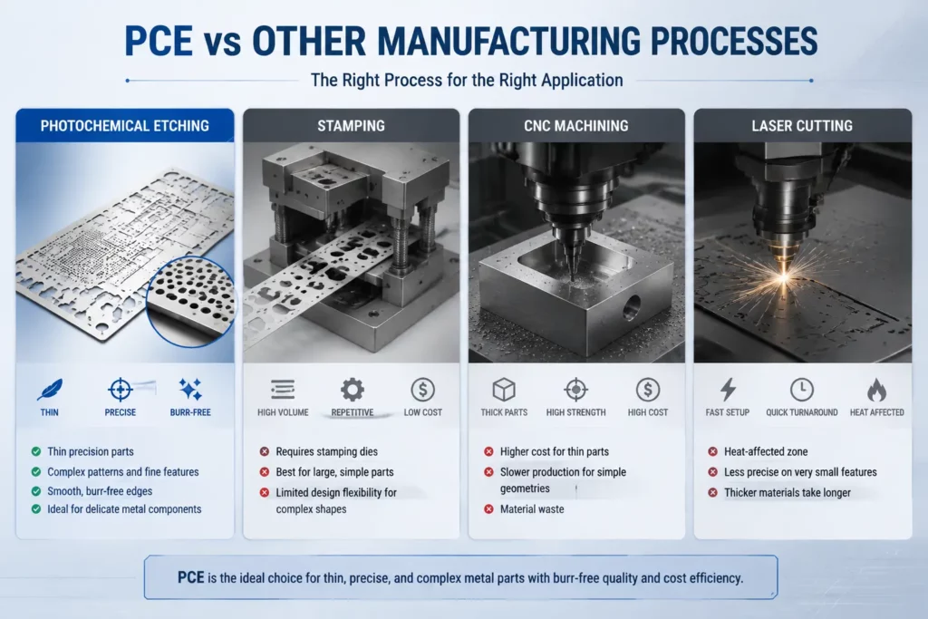
- Photo etching is well suited for thin, complex metal parts where design flexibility and fast tooling changes are important. Unlike stamping, which requires dedicated dies, photochemical machining uses photo-defined patterns instead of hard tooling.
- Stamping is efficient for high-volume production of standard parts. However, it requires an upfront tooling investment.
- CNC machining is suitable for strong, rigid, and thick shielding structures. It is generally more expensive when producing thin parts.
- Laser cutting supports fast design changes and works well for prototypes and simple geometries. However, heat may affect the quality of the cut edges.
- In summary, choose photo etching for thin and detailed shielding parts, stamping for high-volume standard parts, CNC machining for thick and rigid structures, and laser cutting for prototypes or designs that require frequent changes.
What Is Photochemical Etching?
Photochemical etching is a subtractive manufacturing process. Subtractive means that the process removes material to create the final part.
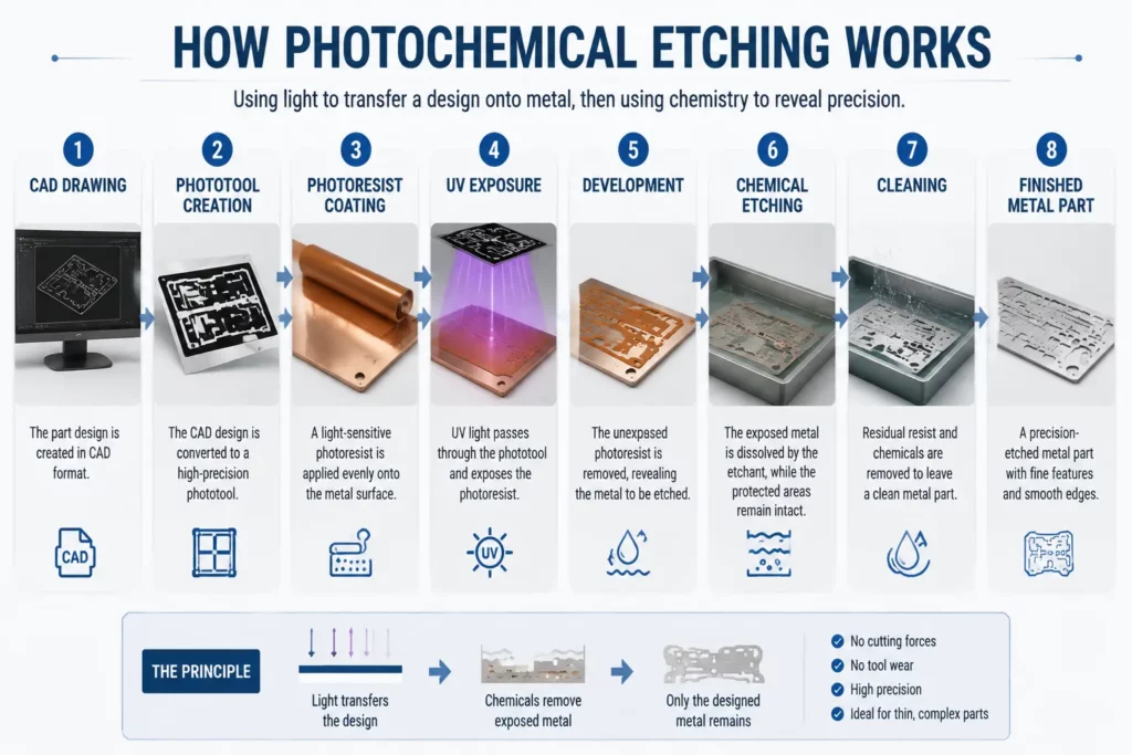
A light-sensitive coating, called photoresist, protects the areas that must remain. Ultraviolet light transfers the component design onto the coated metal. The exposed metal is then removed by a controlled etchant, while the protected metal remains in place.
The result is a flat metal component with the required outside profile, holes, slots, channels, markings, or other details. Because the process does not use a cutting edge, it can produce intricate designs without the mechanical force associated with punching or machining.
Are Photo Etching and Photochemical Machining the Same?
The metal manufacturing industry uses several terms for closely related processes, including photochemical machining (PCM), photo etching, and chemical milling.
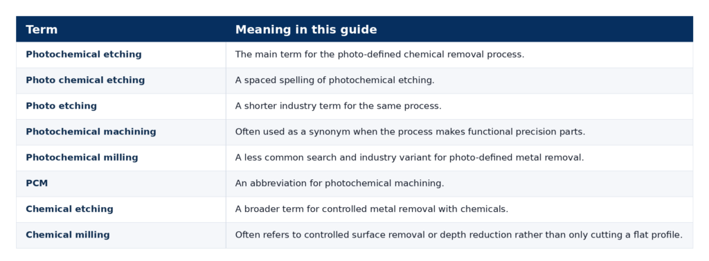
The exact term matters less than the manufacturing requirement. The supplier still needs to know the material, thickness, geometry, tolerance, quantity, and final application.
For a broader introduction to the service category, visit TMNetch’s chemical etching service page.
How Does the Photochemical Etching Process Work?
The process converts a digital drawing into a photo-defined pattern on metal. Each step affects the final accuracy and surface condition.
1. Drawing and DFM Review
The supplier first reviews the drawing for design for manufacturability, or DFM. The review considers material grade, thickness, critical dimensions, hole and slot sizes, feature spacing, half-etched areas, surface finish, quantity, and inspection needs.
This step identifies features that may become difficult to control during etching. It also helps separate critical dimensions from dimensions that can use a wider tolerance.
2. Metal Selection
The selected metal must meet the part’s functional needs. Conductivity, corrosion resistance, strength, spring behavior, weight, formability, and plating requirements can all affect the choice.
The supplier also checks the alloy grade, temper, thickness, and surface condition. Different grades of the same metal may not etch in exactly the same way.
3. Cleaning and Surface Preparation
Oil, dust, oxides, and other surface contamination can reduce photoresist adhesion. The metal is therefore cleaned before coating.
A consistent surface helps the resist bond to the sheet. It also reduces the risk of unwanted etching beneath damaged or poorly bonded areas.
4. Photoresist Coating
A UV-sensitive photoresist is applied to both sides of the metal when the design requires double-sided etching. Heat and pressure help the resist form a consistent layer.
The coating protects the areas that should remain after etching.
5. UV Exposure
The digital design is converted into phototool artwork or another controlled imaging format. Ultraviolet light transfers that pattern onto the photoresist.
Correct alignment is important when the front and back patterns must meet. Alignment affects through-holes, slots, channels, and other double-sided features.
6. Developing
The developing process removes the photoresist from the areas that must be etched. The remaining resist protects the final part geometry.
At this stage, the metal carries the pattern that guides material removal.
7. Chemical Etching
The prepared sheet passes through controlled etching equipment. The etchant removes exposed metal from the front, back, or both sides, depending on the design.
Material grade, thickness, line speed, etchant condition, temperature, and spray control can affect the result. The process must also allow for lateral etching beneath the photoresist. This effect is called undercut.
8. Stripping and Cleaning
After etching, the remaining photoresist is removed. The parts are then cleaned to prepare them for inspection or secondary processing.
Depending on the design, parts may remain connected to a sheet for handling or may separate from the sheet after etching.
9. Inspection
The finished part is checked against the drawing and inspection plan. TMNetch’s photo-etching page lists CMM inspection and quality checks as part of its process.
Inspection should focus on the dimensions and features that affect fit, assembly, or performance. The required method should be agreed before production.
10. Secondary Processing
Some etched parts need additional operations. TMNetch lists in-house electroplating, bending, laser cutting, polishing, and custom packaging on its photo etching service page.
These steps should be planned before etching. Plating, bending, and polishing can change dimensions, hole size, flatness, or surface appearance.
For more information about production systems, see the guide to chemical etching equipment.
What Materials Can Be Photochemically Etched?
Photochemical etching can process many metals, but each alloy needs suitable chemistry and process control. A material should be selected for the final application first, not only for ease of etching.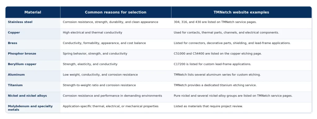
Material approval should include the exact grade and temper. For example, a spring contact may need phosphor bronze or beryllium copper, while an EMI shield may use stainless steel, nickel silver, copper, or plated steel.
Read the separate guide to chemical etching materials and processes for a deeper material overview.
Photochemical Etching Tolerances and Design Guidelines
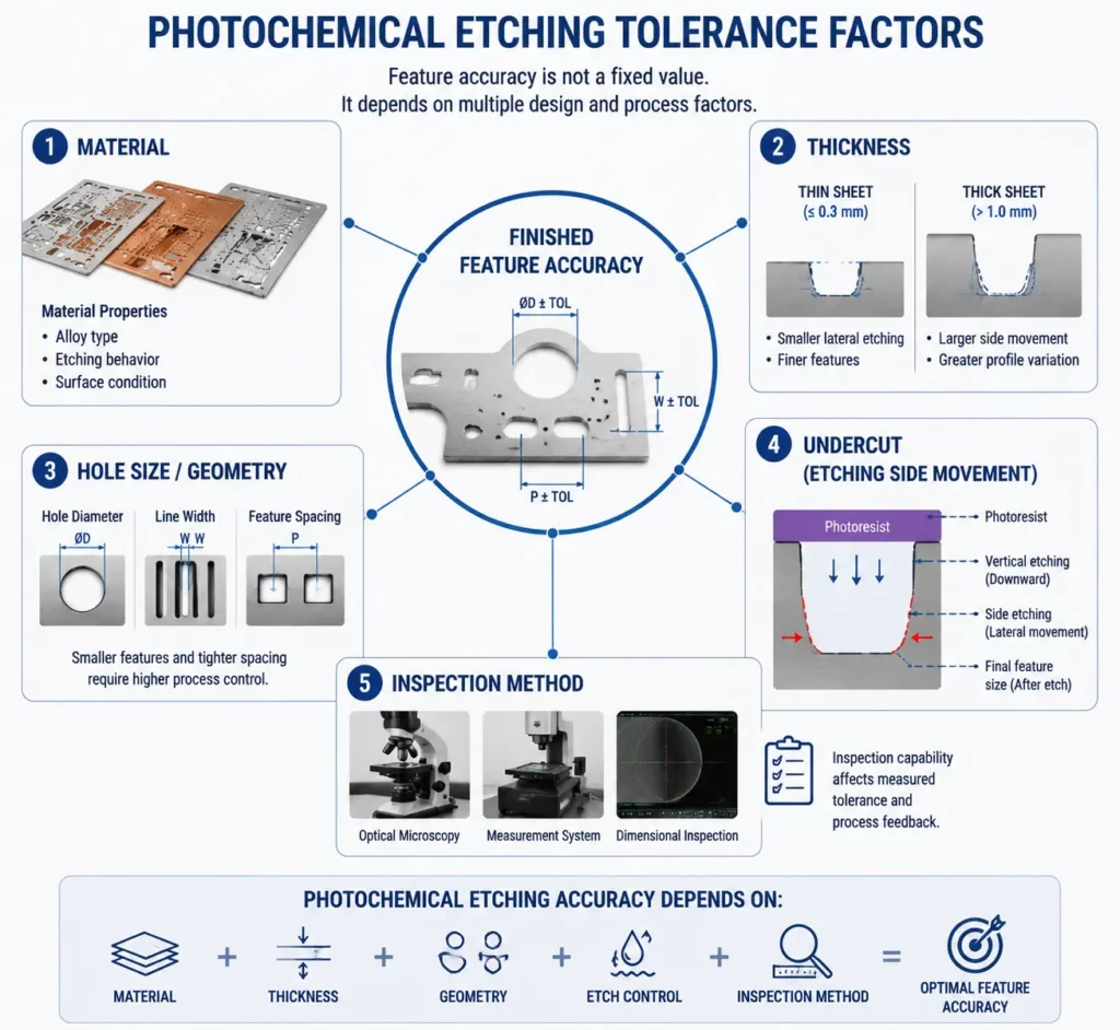
Why Photochemical Etching Tolerances Depend on Material and Thickness? Photochemical etching tolerances are inherently material- and thickness-dependent. A thin stainless steel screen and a thicker titanium plate will never hold the same absolute tolerance. This guide details the design rules that determine achievable accuracy and how to specify them correctly.
The design should account for the way the etchant removes metal both downward and sideways. The supplier adjusts the artwork and process to manage this behavior, but the drawing must still use realistic features.
Material Thickness
Thickness is one of the main design inputs. As material becomes thicker, the etchant must travel farther to cut through the sheet.
Thicker material can increase lateral undercut and make very small openings more difficult to control. This is why feature size and tolerance should always be reviewed together with thickness.
Hole and Slot Size
The smallest practical hole or slot depends on material, thickness, geometry, and process conditions. A published minimum feature should not be applied to every drawing without review.
When a hole or slot becomes very small in relation to the sheet thickness, etchant access and undercut can affect its final size and shape. Dense arrays may also require enough metal between openings to keep the sheet stable.
Web Width and Feature Spacing
A web is the narrow strip of metal between two openings. If it is too narrow, the strip may become weak, uneven, or difficult to hold within tolerance.
The DFM review should consider both individual web width and the overall open-area pattern. Filters and screens with thousands of repeated holes need special attention because small variation can affect the complete sheet.
Undercut and Etch Factor
The etchant does not remove metal only in a straight vertical direction. It also moves sideways beneath the photoresist.
This lateral removal is called undercut. The relationship between vertical depth and lateral removal is often described as the etch factor. Material, etchant condition, thickness, exposure pattern, and process control all affect it.
Inside and Outside Corners
Chemical etching does not always create a perfectly vertical wall or a perfectly sharp internal corner. Inside corners may become more rounded, while outside corners can etch differently because more surface is exposed.
The phototool can compensate for some of this effect. Critical corner shape should still be identified on the drawing.
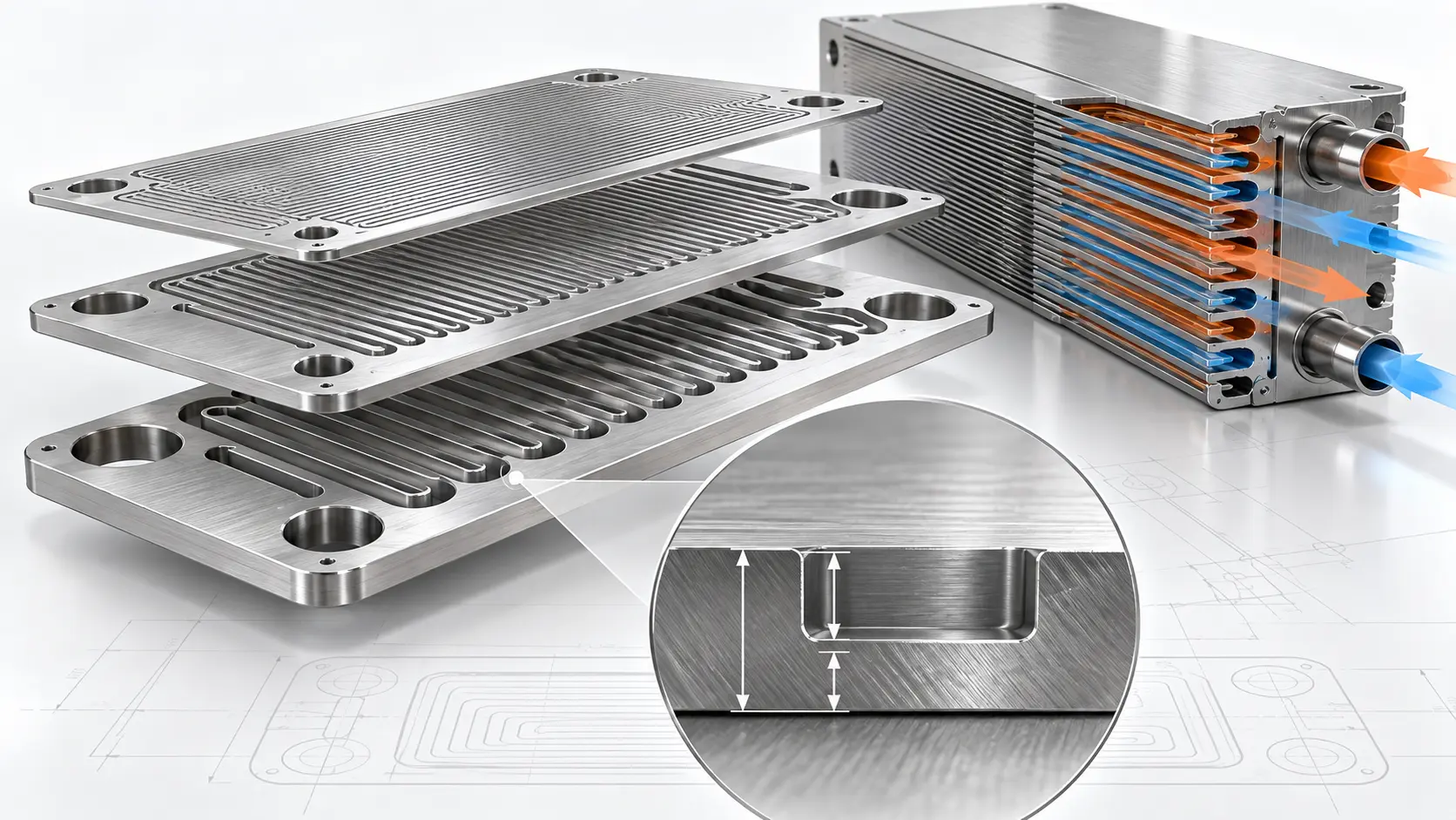
Half-Etched Features
Half etching removes only part of the metal thickness. It can create channels, bend lines, logos, part numbers, surface details, or multi-depth features.
Depth control is different from through-etching. The supplier needs to review the required depth, tolerance, side of the sheet, remaining thickness, and relationship to nearby through-features.
For a deeper look at this subject, read the guide to 3D and multi-depth photo chemical etching.
Part Size and Flatness
The starting material’s surface and flatness affect the finished part. Large open areas, thin webs, uneven patterns, and later secondary processes can also influence flatness.
If flatness is critical, include the requirement in the drawing. Do not assume that a general linear tolerance also controls flatness.
Inspection Requirements
The inspection method should match the feature. A standard measuring tool may work for an outside dimension, while fine holes, dense patterns, or profiles may need optical or vision measurement.
Define critical dimensions, sampling requirements, reports, material certificates, and traceability needs in the RFQ. This allows the supplier to include inspection in the production plan.
Advantages of Photochemical Etching
Photochemical etching offers several advantages for suitable thin-metal designs.
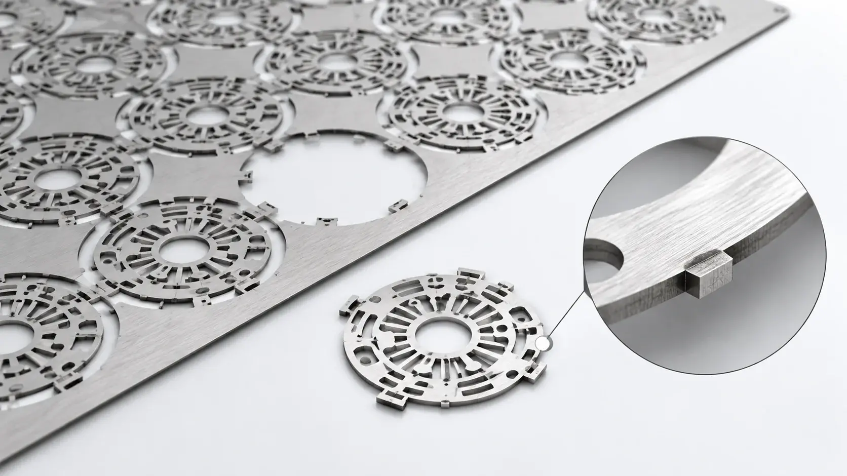
Burr-Free Edges
Punching and mechanical cutting can leave raised material at the cut edge. Photochemical etching removes metal through a controlled chemical reaction, so it avoids mechanical shear burrs.
Buyers should still define edge and surface requirements. Chemical processing has its own edge profile and should not be described as identical to a machined wall.
No Heat-Affected Zone
Laser cutting uses focused heat. Photochemical etching does not use a concentrated heat source to create the profile, so it avoids a laser-type heat-affected zone.
This can help when the part must keep the original material temper or when thermal distortion is a concern.
No Mechanical Cutting Stress
The process does not press a punch or cutting tool through the material. It therefore avoids the direct cutting force that can distort delicate thin parts.
This is useful for fine webs, thin shims, spring features, filters, and detailed flat components.
Digital Tooling and Faster Design Changes
The design is created from digital artwork rather than a hard production die. Engineers can revise the pattern without rebuilding a progressive stamping tool.
This makes the process useful during product development. It can also reduce tooling risk when a design may change after testing.
Complex Features Are Processed Together
Holes, slots, outer profiles, and repeated patterns are defined in the same artwork. The etching step removes all exposed areas together.
As a result, adding more openings does not create a separate cutting operation for every feature. Material use, sheet layout, tolerance, and inspection still affect cost.
Prototype-to-Production Flexibility
The same basic photo-defined process can support prototypes and repeated production. This helps teams test a design before moving to larger quantities.
For repeat orders, drawing revision control and process documentation become important. The supplier should confirm how it manages artwork versions and inspection requirements.
Limitations of Photochemical Etching
PCE is not the best process for every metal component. Understanding its limits prevents unrealistic tolerances and costly redesigns.
It Is Mainly a Thin-Sheet Process
Photochemical etching works best for flat metal sheet and foil. As material becomes thicker, etch time, undercut, minimum feature size, and edge geometry become more difficult to control.
A thick structural component may fit CNC machining, laser cutting, waterjet cutting, or another process better.
Feature Size Is Linked to Thickness
Very small holes and narrow webs become harder to produce as thickness increases. A minimum feature value from one project should not be reused on another alloy or thickness without review.
Perfectly Vertical Walls Are Not Typical
Chemical removal creates an edge profile influenced by undercut. If the application requires a deep feature with a near-vertical wall, another process may be more suitable.
True 3D Geometry Is Limited
PCE can create half-etched channels, markings, bend lines, and controlled depth features. It does not replace full 3D CNC machining for deep pockets, complex curved surfaces, or thick structural forms.
Starting Surface Quality Matters
The process does not automatically remove every mark or defect from the original sheet. Surface quality, coating adhesion, and cleanliness can affect the finished appearance.
Chemical Management Is Required
Industrial etching uses controlled chemicals. A qualified manufacturer must manage process chemistry, rinsing, waste, worker safety, and environmental requirements.
Read more about the limitations of photochemical etching before finalizing a difficult design.
Common Photochemical Etching Applications
TMNetch applies photochemical etching to several component groups. Each product uses the same core process for a different functional need.
Metal Mesh Filters and Screens
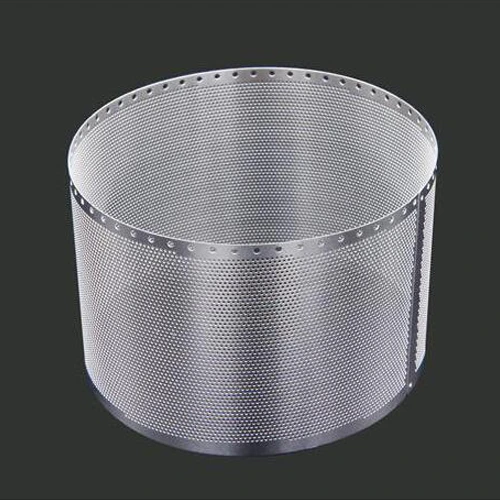
Metal mesh filters can contain repeated round, square, or custom openings. PCE creates the holes and outside profile in the same process.
Applications include appliance filters, audio screens, medical and industrial screens, food-processing filters, and other custom filtration parts. Buyers should define aperture size, open area, material, thickness, surface finish, and cleanliness.
EMI/RFI Shielding
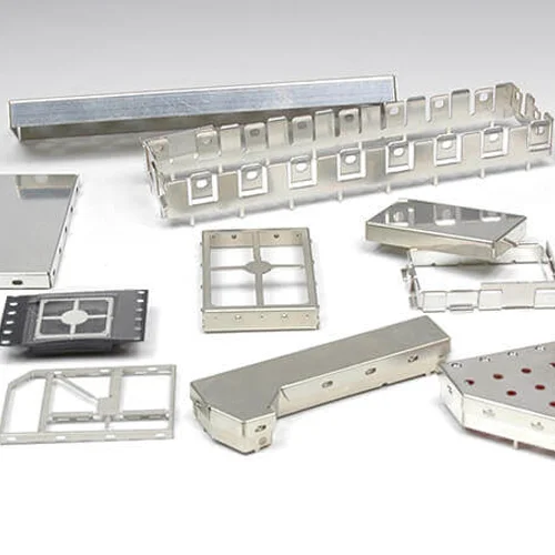
EMI/RFI shielding parts can include covers, frames, clips, bend lines, ventilation holes, and etched markings. TMNetch lists stainless steel, copper, nickel silver, plated steel, and copper-nickel-zinc alloys for shielding designs.
The drawing should identify bend areas, grounding features, coating or plating, PCB layout, and assembly requirements.
Custom Lead Frames and Electrical Contacts
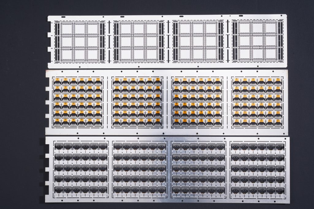
Custom lead frames need precise conductive paths and repeated fine geometry. TMNetch lists beryllium copper, brass, phosphor bronze, stainless steel, and nickel silver for chemically etched lead-frame applications.
Material temper, plating, flatness, pitch, and package requirements should be reviewed before production.
Fuel Cell Bipolar Plates
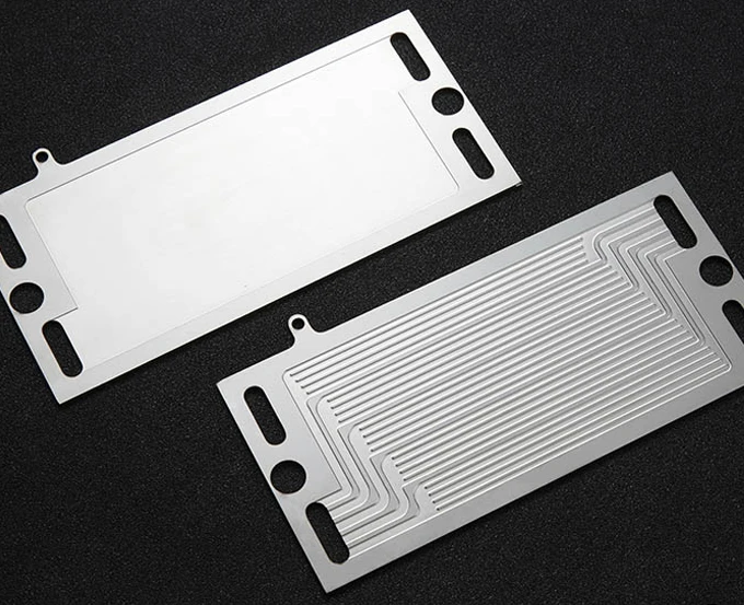
Bipolar plates can use etched flow channels and multi-depth patterns. TMNetch lists prototype-to-production support and dual-depth channel designs for these projects.
The complete manufacturing plan may also involve coating, welding, bonding, cleaning, or inspection. These requirements should be defined with the final stack design in mind.
Vapor Chamber Components
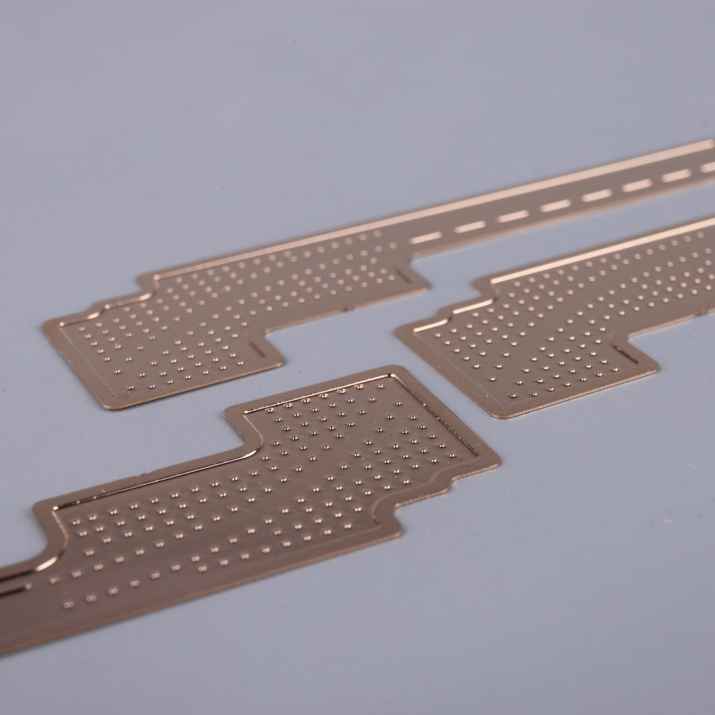
Vapor chamber components may use thin copper sheets with internal channel or wick patterns. Etching can form detailed flat patterns without mechanical cutting stress.
The etched structure is only one part of the finished thermal device. Joining, sealing, cleaning, and final testing require separate process control.
Speaker Grilles
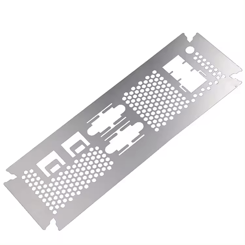
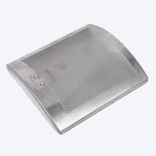
Photo-etched speaker grilles can combine fine openings, decorative patterns, and a finished outer profile. Materials listed by TMNetch include stainless steel, aluminum, and nickel alloys.
The buyer should define open area, acoustic needs, appearance, coating, flatness, and assembly method.
Shims, Washers, Spacers, and Encoder Discs
Thin shims, washers, spacers, and encoder discs often contain precise profiles, holes, and repeated slots. PCE is useful when mechanical cutting could create burrs or deform fine features.
Critical thickness, flatness, angular accuracy, hole pattern, and surface requirements must be stated on the drawing.
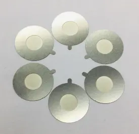
Photo-Etched Model Parts
Photo-etched model parts use thin metal to reproduce railings, grilles, panels, brackets, and other scale details. TMNetch lists stainless steel, aluminum, copper alloys, nickel alloys, and titanium alloys for these parts.
The selected thickness should match both visual scale and handling strength.
Quality Control and Inspection
Quality planning begins before the metal enters the etching line. A supplier must understand which dimensions affect function and how each one will be checked.
TMNetch states that its production operates under an ISO 9001:2015 quality system. Its photo-etching process lists CMM inspection and quality checks. Its titanium etching page also lists 2D vision inspection, First Article Inspection, and Outgoing Quality Control reporting for titanium projects.
A project may require some or all of the following:
Material grade and thickness verification
Drawing and revision review
First article inspection
Visual surface inspection
Dimensional or optical inspection
Plating or coating inspection
Material certificates
Batch or order records
Final cleaning and packaging checks
Do not leave these requirements until after sampling. Inspection method, sampling level, report format, and critical dimensions can affect price and lead time.
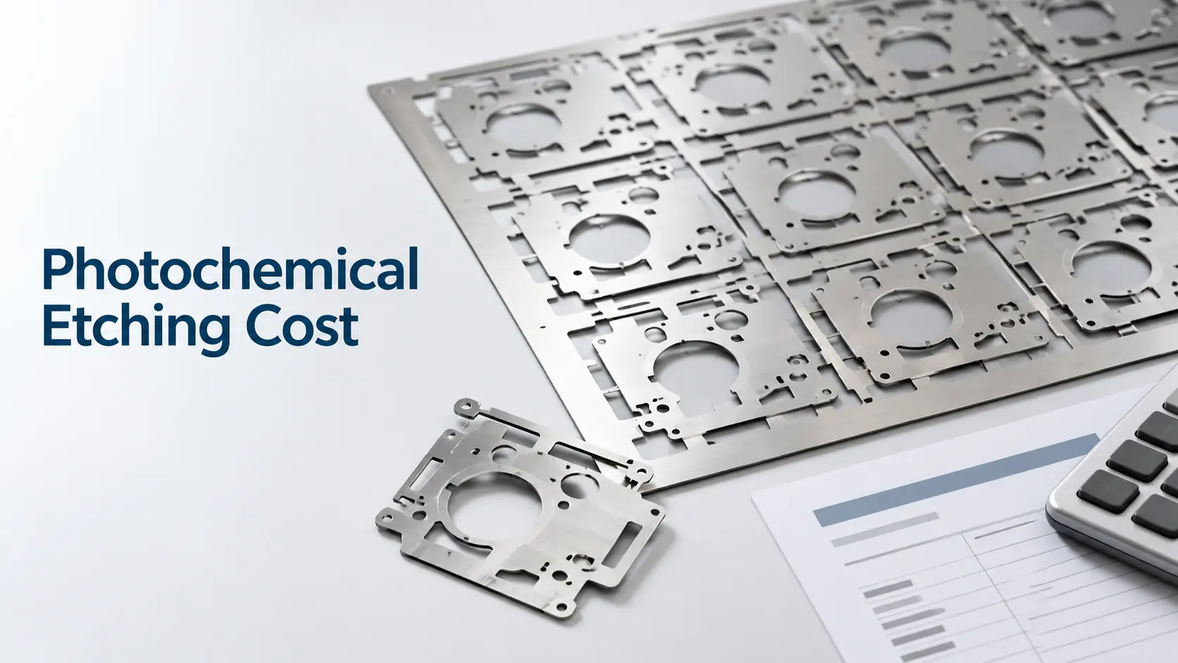
What Affects Photochemical Etching Cost and Lead Time?
Photochemical etching cost cannot be calculated from part length and width alone. The supplier must review the complete drawing and production requirement.
Important cost and scheduling factors include:
Material type, grade, and temper
Material thickness
Part size and sheet layout
Quantity and expected repeat demand
Critical tolerances
Minimum holes, slots, and web widths
Half-etched or multi-depth features
Surface and cosmetic requirements
Plating, polishing, bending, laser cutting, or other secondary work
Inspection reports and material documentation
Cleaning, packaging, and shipping requirements
Digital artwork can reduce the need for expensive hard tooling. However, it does not remove the need for DFM, process setup, material, inspection, or finishing.
The most accurate quotation comes from a complete RFQ. If the design is still changing, state that clearly so the supplier can separate prototype needs from the final production plan.
What Should You Include in a Photochemical Etching RFQ?
Send enough information for an engineering review. A useful RFQ should include:
A 2D drawing or CAD file
Material name and exact grade
Material thickness and temper, if relevant
Prototype quantity and production quantity
Expected annual demand
Critical dimensions and tolerances
Minimum hole, slot, and web sizes
Half-etched areas and required depth
Surface finish, plating, or coating
Flatness and edge requirements
Inspection and documentation needs
Packaging requirements
Final application and assembly conditions
Label critical characteristics clearly. Avoid applying the tightest tolerance to every dimension unless the application truly needs it.
Why Work With TMNetch?
TMNetch states that it has specialized in photochemical etching since 2011. The company operates an ISO 9001:2015-certified facility in Dongguan, China, with automated etching and supporting production systems.
TMNetch supports custom parts from drawing review through production. Its website lists stainless steel, copper, brass, phosphor bronze, beryllium copper, aluminum, titanium, nickel alloys, and other suitable metals.
For projects that need more than etching, TMNetch lists in-house electroplating, bending, laser cutting, polishing, and custom packaging. This allows the etching and secondary operations to be reviewed as one manufacturing plan.
Before quotation, the engineering team can review the drawing, material, thickness, tolerance, quantity, surface requirements, inspection needs, and secondary processes.
Submit Your Drawing for a Photochemical Etching Review
Send your CAD file, material grade, thickness, quantity, critical tolerances, finish, and application requirements to TMNetch for technical review and quotation.
TMNetch Photo Etching Capabilities
TMNetch publishes the following general information on its current photo-etching and product pages. These figures are reference capabilities, not automatic acceptance limits for every material and design.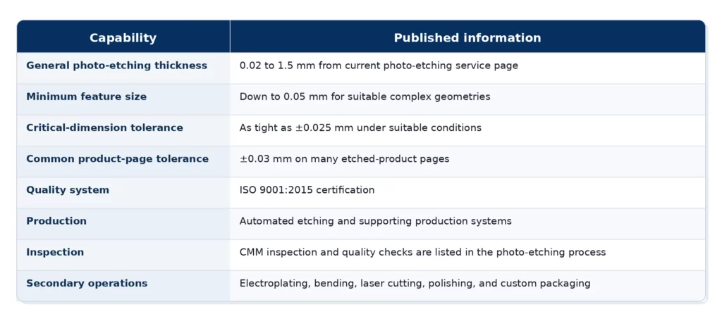
Final capability depends on material type, thickness, part size, feature geometry, hole diameter, slot width, spacing, half-etched areas, surface requirements, and inspection method. Send the drawing for technical review before fixing production tolerances.
Frequently Asked Questions
What is photochemical etching?
Photochemical etching is a subtractive metal manufacturing process. It uses photoresist, UV exposure, and controlled chemical etching to remove selected areas from a metal sheet. The process creates thin, detailed components without mechanical cutting force or focused cutting heat.
Is photochemical etching the same as photochemical machining?
The terms are often used as synonyms. Photo etching, photo chemical etching, photochemical machining, and PCM usually describe the same photo-defined chemical process when it is used to manufacture precision metal components.
What metals can TMNetch photochemically etch?
TMNetch lists stainless steel, copper, brass, phosphor bronze, beryllium copper, aluminum, titanium, nickel and nickel alloys, molybdenum, and other suitable specialty metals. Final approval depends on the exact grade, thickness, geometry, tolerance, and surface requirements.
How accurate is photochemical etching?
Accuracy depends on material, thickness, part size, feature geometry, etch depth, and inspection method. TMNetch product pages commonly list ±0.03 mm, while its photo-etching service page states that suitable critical dimensions can reach ±0.025 mm. A drawing review is required before confirming tolerance.
What material thickness can TMNetch photo etch?
TMNetch’s current photo-etching service page lists a general processing range of 0.02 to 1.5 mm. Material-specific pages may publish different ranges for particular applications. Confirm the exact alloy, thickness, and geometry with the engineering team.
What is the minimum photochemical etching feature size?
TMNetch’s photo-etching service page lists features down to 0.05 mm for suitable complex geometries. This is not a universal value for every hole, slot, web, material, or thickness. The drawing must be reviewed before the feature is approved.
Does photochemical etching create burrs?
The process avoids the raised shear burrs created by punching or mechanical cutting. The final edge still has an etched profile affected by material thickness and undercut, so critical edge requirements should be stated on the drawing.