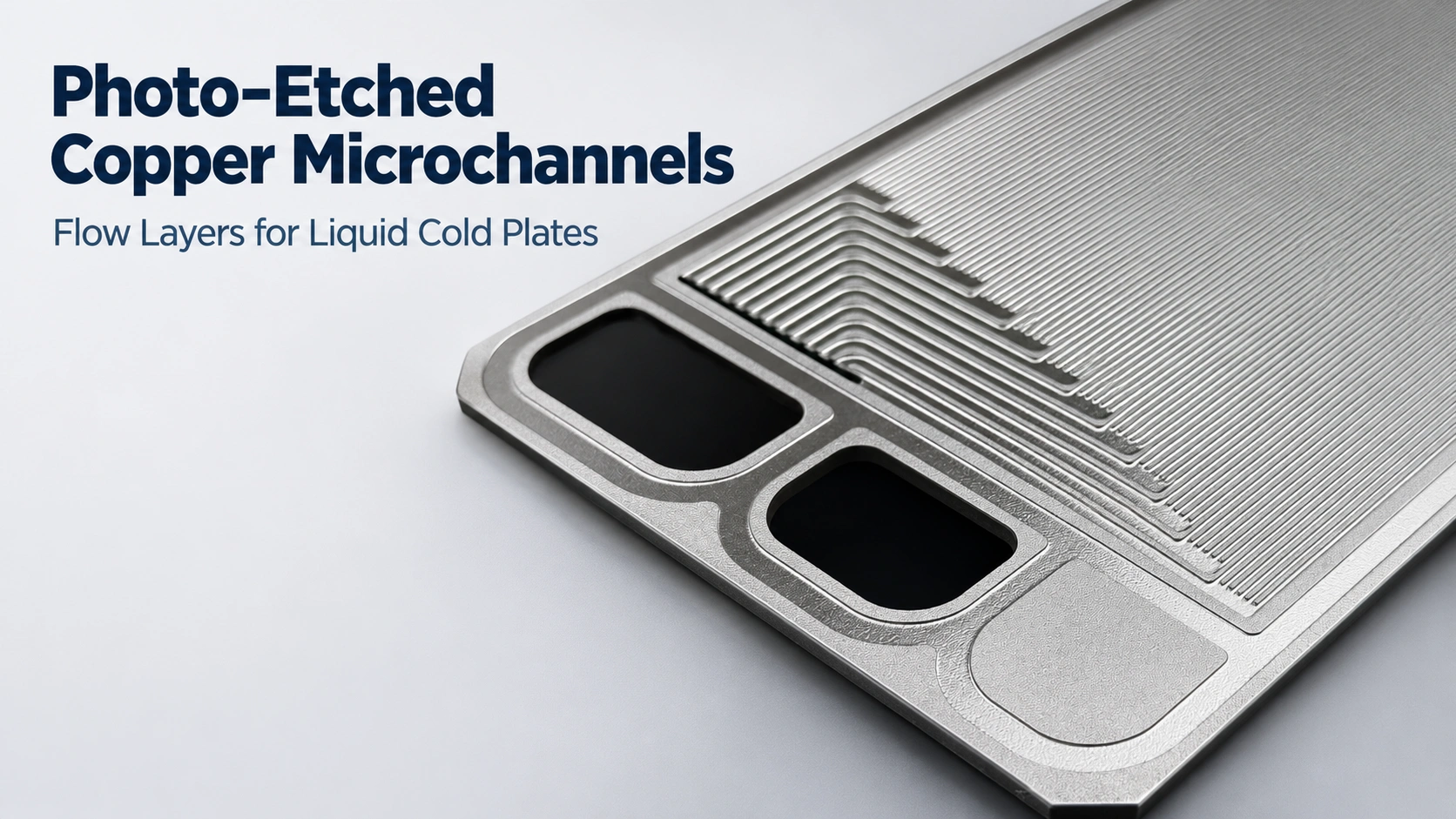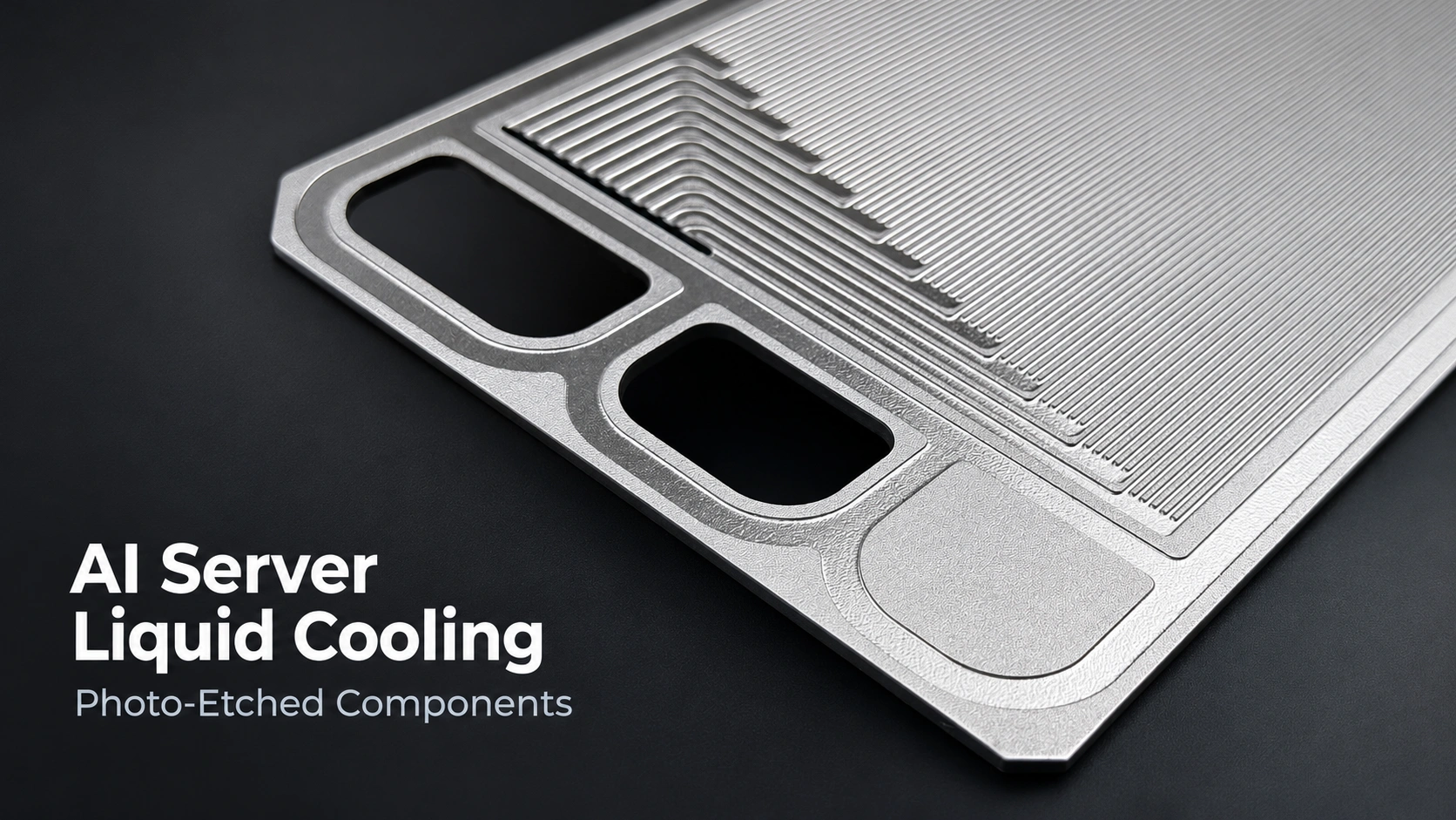

Choose a manufacturing route by checking whether it can deliver the required plate, then compare cost at the agreed delivery condition. This bipolar plate manufacturing process comparison covers metal plates made by photochemical etching, stamping, hydroforming and computer numerical control, or CNC, machining. Start with shared functional requirements and a controlled drawing. Ask each supplier to identify any changes needed for its process. Compare geometry, inspection evidence, revision costs and expected quantities before selecting a route. A lower quotation means little if it covers a different part or leaves essential finishing work outside the price.
Key takeaway:
Define the drawing and delivery state first. Screen each process for feasible geometry and material condition. Compare the cost of accepted plates, including the agreed downstream work. Then choose a route suited to the development stage, and review that choice again before committing to production tooling.
Define the Drawing and Delivery State Before Comparing Processes
Give suppliers the same functional baseline: fluid interfaces, sealing areas, critical dimensions and acceptance requirements. Specify the alloy and material condition, while making any permitted substitutions clear.
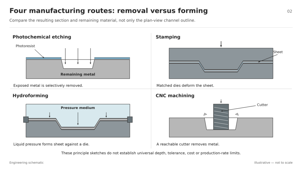
Separate starting sheet thickness from channel depth, remaining wall thickness and forming height. Photochemical etching removes exposed metal through a patterned resist. Stamping and hydroforming create channels by deforming sheet. An etched groove and a formed corrugation therefore need separate cross-sectional definitions.
A fair comparison does not require identical starting thicknesses when different routes need different stock. It requires agreed functional limits and a recorded list of proposed deviations. Review their effects before accepting a revised design.
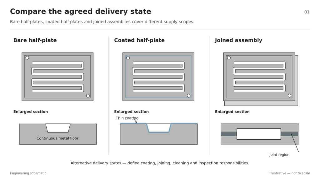
Also define the delivery state: bare half-plate, coated half-plate or joined assembly. State who supplies coating, joining, cleaning and inspection. Include sample quantities, annual demand and expected design changes.
Keep metal-sheet comparisons separate from graphite-block machining. For the wider production sequence, see the bipolar plate manufacturing process from drawing to delivery.
Bipolar Plate Manufacturing Process Comparison Matrix
Use this matrix as a quotation checklist. Ask suppliers to fill the evidence gaps for the actual drawing, rather than treating the entries as guaranteed capabilities.
| Route | Geometry and depth to compare | Cost and revision inputs | Dimensional evidence to request | Stage and volume decision |
|---|---|---|---|---|
| Photochemical etching | Etch depth, undercut beneath the mask, remaining wall and features on opposing faces | Pattern artwork, panel layout, etching, cleaning and artwork revisions | Channel sections, depth distribution, widths and surface condition | Assess iteration effort and repeatability at the quoted quantities |
| Stamping | Forming height, corner radii, local thinning and springback | Dies, correction trials, maintenance, cycle time and changeovers | Profiles, thinnest locations, cracks, wrinkles and repeated-part measurements | Compare tooling commitment with design stability and production needs |
| Hydroforming | Channel filling, wall thickness and shape under the proposed pressure cycle | Die, pressure equipment, trials, cycle time and downstream operations | Measurements from the specified stock and proposed tooling | Require project evidence instead of assigning a fixed volume category |
| CNC machining | Tool access, cutter geometry, fixturing and final machined section | Programming, fixtures, tool life, machining time and finishing | Dimensions, surface finish and any distortion after release | Compare the specified metal, geometry and delivery condition |
Three distinctions matter:
- Removal versus forming: compare the resulting cross-section and remaining material, not just the channel outline.
- Investment versus recurring cost: show tooling separately from the cost of repeat deliveries.
- A sample versus a process: one accurate feature does not establish repeatable production capability.
Metal bipolar-plate micromachining involves material-specific tooling and surface-quality questions. Evaluate those directly rather than labeling CNC as suitable only for research.
For an initial shortlist, consider etching where selective removal can meet the required channel section and remaining wall. Compare stamping and hydroforming where the design calls for a formed sheet profile. Assess CNC where cutter access and stock geometry suit the machined section. Require measurements and a comparable quotation for each shortlisted option.
Compare Channel Depth and Tolerance Against an Acceptance Plan
Channel Depth Is Not the Same as Sheet Thickness or Forming Height
For an etched plate, define depth from an agreed reference surface and specify the required remaining wall. Where both faces contain channels, review their relative positions.
For a formed plate, specify the channel profile and the wall thickness after forming. Hydroforming pressure and material condition affect channel shape, thinning and springback. The drawing should therefore describe the required final geometry, not just the starting gauge.
For an etching-specific review, use the chemical etching design guidance for bipolar plate flow channels.
Compare Measured Features, Not a Single Accuracy Label
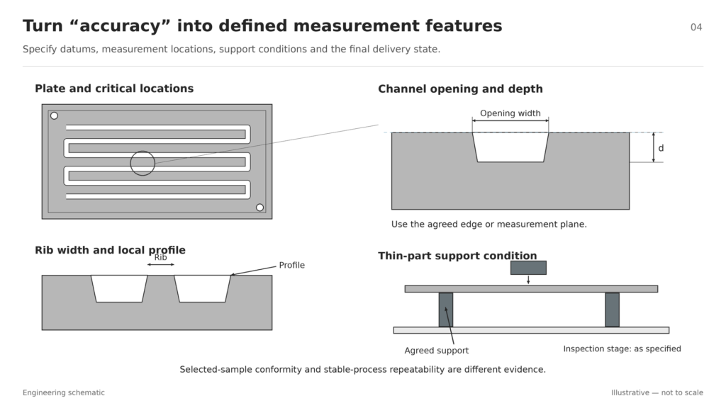
Ask for channel depth, width, rib width, profile and plate flatness against agreed datums. Identify the features that control sealing, joining and assembly.
Record whether measurements apply to a bare, coated or joined plate. Agree how thin parts are supported during inspection.
Keep sample conformity separate from batch repeatability. Process capability compares the variation of a stable process with specification limits. A selected sample alone cannot establish that evidence. Functional acceptance should also match the intended delivery state.
Compare Cost per Accepted Delivered Plate
Separate Development Cost from Recurring Production Cost
Request separate lines for engineering, artwork or dies, fixtures, trials and design revisions. Then compare recurring material, processing and finishing costs.
Include a revision scenario: what changes if a channel width, port position or sealing feature moves? Ask which tools must change and whether new samples or inspection programming are included.
Tool life, equipment utilization and production rate belong in a manufacturing cost model. The linked 2015 analysis is useful for its method; use current supplier quotations for prices.
Include Yield, Inspection and the Agreed Delivery State
Use a shared purchasing calculation:
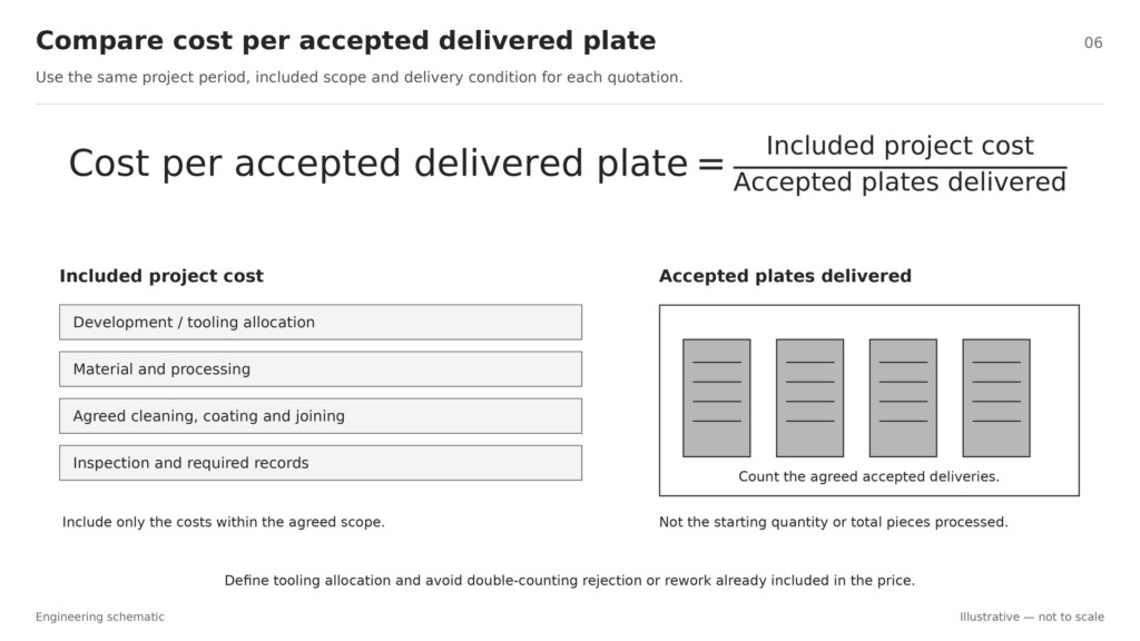
Cost per accepted delivered plate = Included project cost ÷ Accepted plates delivered
Define the project period and whether tooling is paid upfront or spread across deliveries. Include cleaning, finishing, coating, joining, inspection and reports where these belong to the agreed scope.
Check how rejected parts and rework are charged. Avoid counting their cost twice if the quotation already covers accepted pieces.
Compare the same sample, pilot and production quantities. Request updated quotations when the drawing stabilizes. This makes the decision sensitive to the actual project, rather than an assumed universal break-even volume.
Choose by Development Stage, Then Reassess Before Production
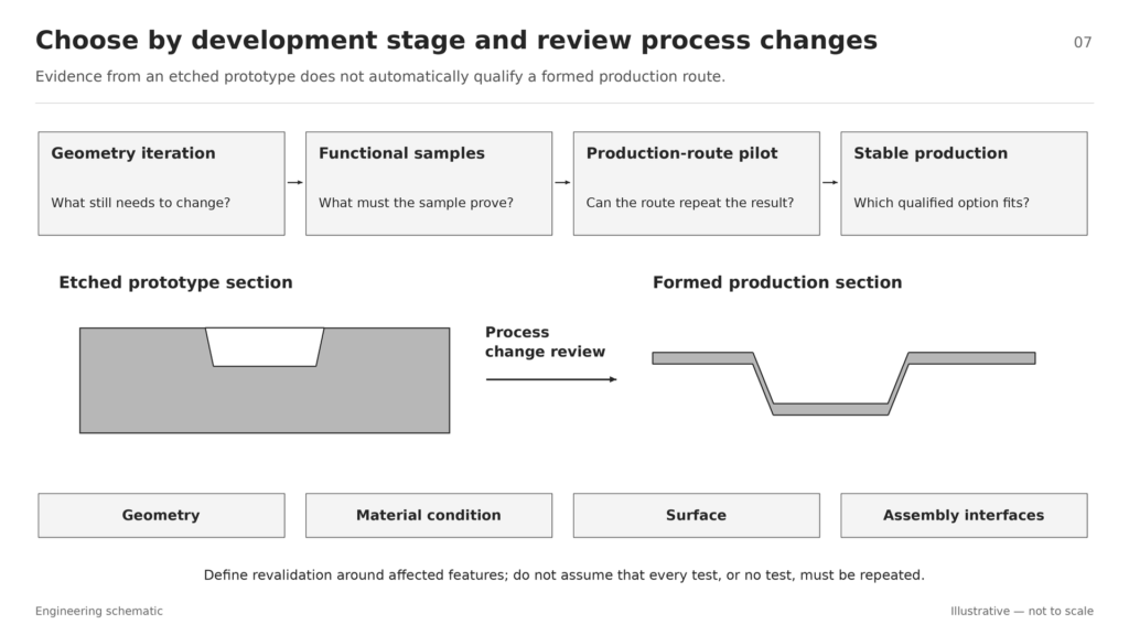
Use the next decision—not annual volume alone—to guide process selection.
| Development stage | Main question | What to compare | Evidence needed before moving forward |
|---|---|---|---|
| Concept and geometry iteration | What still needs to change? | Feasibility, revision effort and sample purpose | Controlled drawing, listed deviations and measured sections |
| Functional samples | Does the proposed plate meet its test purpose? | Representative geometry, material, surface and assembly interfaces | Recorded test conditions and sample limitations |
| Production-route samples and pilot | Can the intended route deliver acceptable parts repeatedly? | Critical dimensions and the specified downstream condition | Repeat measurements, inspection plan and delivery acceptance |
| Stable production | Which qualified option meets cost and supply needs? | Accepted cost, tooling allocation, capacity and change control | Controlled process, current quotations and quality records |
Small quantities can still justify samples from the intended production route when the purpose is to qualify that route. Conversely, an early geometry study may prioritize affordable changes over production cycle time.
Engineering note: Passing a test with an etched prototype does not automatically qualify a stamped version. Material removal and sheet forming create different cross-sections; forming can also introduce local thinning and springback. Define revalidation around the changed features, material condition, surfaces and assembly interfaces. Avoid assuming either that every test must be repeated or that none is needed.
Before ordering production tooling, hold a review of drawing changes, sample evidence, acceptance requirements and remaining technical questions.
Prepare a Comparable RFQ—and Check Whether Etching Fits
Build the request for quotation, or RFQ, around six inputs:
- Drawing revision and editable geometry.
- Alloy, material condition and starting thickness or permitted range.
- Channel sections, critical dimensions and acceptance requirements.
- Sample, batch and annual quantities.
- Bare, coated or joined delivery state, with responsibilities assigned.
- Expected revisions, target schedule and required quality documents.
Request a list of exceptions alongside the price. A description such as “thin plate with complex channels” is only a starting point; have the supplier review the actual geometry and delivery requirements.
TMNetch Case: Reviewing a Combined Manufacturing Route
In earlier TMNetch flow-plate work combining etching and laser cutting, the recorded route used both processes. The project information identifies 316 stainless steel and titanium as commonly used materials.
The practical lesson is to review the whole component before assigning every feature to one process. Consider detailed channel features and large profiles together when discussing the manufacturing route.
This is related flow-plate experience, rather than a controlled comparison of the four bipolar-plate routes. It supports a project-specific discussion without establishing a fuel-cell performance or cost advantage.
Check Whether Chemical Etching Fits Your Bipolar Plate Drawing
Comparing etching with forming or machining? Share your drawing, material specification, critical dimensions, delivery condition and quantities with TMNetch for a bipolar plate manufacturing review. Confirm feasible geometry, inspection scope and quotation assumptions before choosing the route.
Frequently Asked Questions
Is Chemical Etching Better Than Stamping for Bipolar Plates?
Compare both against the required cross-section, remaining wall, acceptance plan and delivered cost. Selective removal and sheet forming create different geometries, so the choice needs drawing-specific evidence.
At What Production Volume Should a Project Change Manufacturing Processes?
Calculate the project’s break-even point using current quotations, tooling costs, accepted yield, revision expectations and delivery scope. Reassess when those inputs change.
Can an Etched Prototype Validate a Stamped Production Plate?
It can support tests for which its geometry, material and condition are representative. Qualifying the stamped route also requires evidence from stamped parts, including forming-related features and the agreed delivery state.