
A heat exchanger is a device that transfers thermal energy between streams at different temperatures. In most designs, a metal wall keeps the streams separate while heat passes from the hotter side to the colder side. Engineers use heat exchangers for heating, cooling, condensation, evaporation and waste-heat recovery.
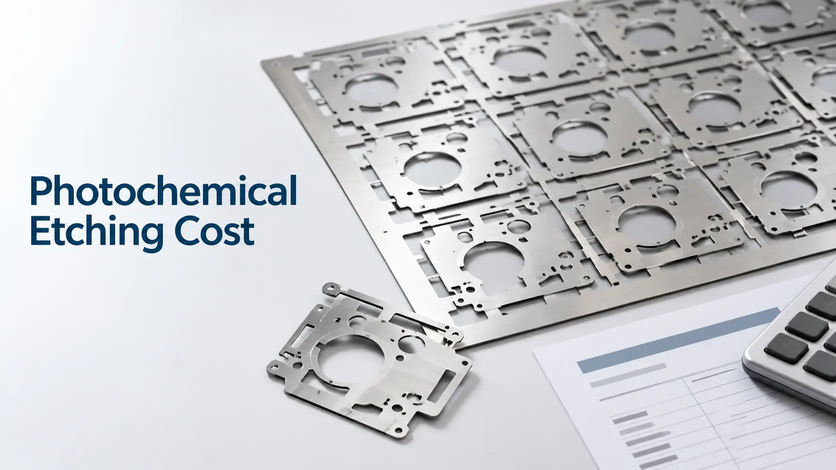
The idea is simple, but good performance requires more than a conductive metal surface. Flow arrangement, surface area, pressure drop, fouling, material compatibility and maintenance access all affect the final design. For thin metal plates requiring complex channels or flow-distribution features, chemical etching services can provide a tooling-free manufacturing option once the thermal and hydraulic design has been defined.
Key Takeaways
- A temperature difference drives heat from the hot stream to the cold stream.
- Most indirect heat exchangers combine convection on both fluid sides with conduction through a separating wall.
- Shell-and-tube, plate, air-cooled, plate-fin and printed-circuit designs solve different operating problems.
- Counterflow usually maintains a stronger average temperature difference than parallel flow.
- Higher heat transfer must be balanced against pressure drop, fouling, corrosion and cleaning requirements.
- In compact exchangers, channel geometry and flow distribution can be as important as the plate material.
What Does a Heat Exchanger Do?
A heat exchanger moves energy rather than “creating cold.” It may cool a hot process stream, heat a cold feed, condense a vapor, evaporate a liquid or recover energy that would otherwise leave a system. In refrigeration, for example, an evaporator absorbs heat while a condenser rejects it. In a heat-recovery system, one process stream can preheat another and reduce demand for external heating and cooling utilities.
How Does a Heat Exchanger Work?
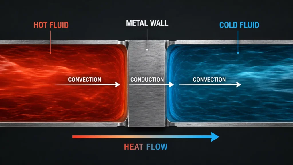
In a typical indirect-contact exchanger, heat follows three steps. Convection moves heat from the hot fluid to the wall. Conduction carries it through the tube or plate. Convection then moves it from the wall into the colder fluid. In most conventional fluid-to-fluid heat exchangers, convection and conduction dominate. Radiation may become important when one or both streams exchange heat through very hot surfaces, flames, combustion gases or radiative enclosures.
For a steady, single-phase stream with nearly constant heat capacity, the heat duty can be estimated from:
Q=m˙cpΔT
Here, (Q) is the heat-transfer rate, (m˙) is mass flow rate, (c_p) is specific heat capacity and (ΔT) is temperature change. Phase-change duties require an enthalpy balance that includes latent heat. (Singapore NEA; ASHRAE)
Another useful relationship is:
Q=UAΔTlm
The overall heat-transfer coefficient (U) combines the main thermal resistances. (A) is the effective surface area, and (ΔTlm) is the log mean temperature difference. Multipass and crossflow arrangements may require a correction factor (F), giving (Q=UAFΔTlm). (ASHRAE)
A Worked Heat-Duty and LMTD Example
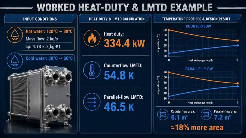
Consider a water-to-water exchanger in which the hot stream is cooled from 120°C to 80°C. If its mass flow rate is 2 kg/s and the assumed specific heat capacity is 4.18 kJ/(kg·K), the required heat duty is:

For an illustrative cold-side condition of 30°C entering and 60°C leaving, the energy balance requires a cold-water flow rate of approximately:

For counterflow, the two terminal temperature differences are:
ΔT1=120−60=60 K
ΔT2=80−30=50 K
Therefore:

If an illustrative overall heat-transfer coefficient of 1.0 kW/(m²·K) and a correction factor of 1.0 are assumed, the preliminary area is approximately:

Using the same terminal temperatures in parallel flow gives an LMTD of approximately 46.5 K and a calculated area of about 7.2 m²—roughly 18% more area under these specific assumptions.
This is only a teaching calculation. A real design must also establish allowable pressure drop, temperature-dependent fluid properties, fouling resistance, wall resistance, phase change, flow distribution and the appropriate correction factor. The governing relationships are consistent with the heat-exchanger design methods summarized by the ASHRAE Handbook—Fundamentals and the National Environment Agency’s industrial heat-exchanger guidance.
How Do Flow Arrangements Differ?
In parallel flow, both streams enter from the same end and move in the same direction. The temperature difference is largest at the inlet and falls along the exchanger. In counterflow, the streams enter from opposite ends, which usually maintains a more consistent temperature difference. Crossflow places the two flow directions across one another and is common in radiators and air coolers. (Singapore NEA; Ipieca)
Counterflow is often thermally favorable, but it is not automatically the best system choice. Real shell-and-tube exchangers can combine counterflow, parallel flow and crossflow because of multiple tube passes and shell-side baffles. The final arrangement must also meet pressure, cleaning and mechanical requirements.
What Are the Main Types of Heat Exchangers?
Double-Pipe Heat Exchangers
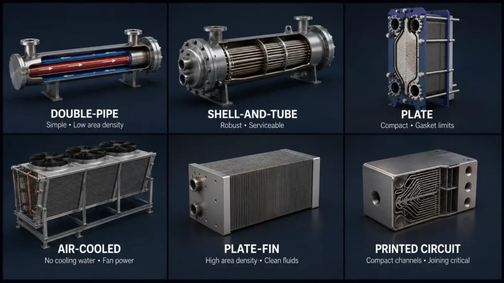
A double-pipe exchanger places one pipe inside another. It is simple and can use parallel or counterflow, but its limited surface area suits smaller duties.
Shell-and-Tube Heat Exchangers
A shell-and-tube exchanger contains a tube bundle inside a cylindrical shell. One fluid travels inside the tubes, while the other flows around them. Tube sheets secure the tubes, and shell-side baffles support the bundle and redirect flow across it. ASHRAE notes that baffle number and spacing affect shell-side velocity, heat transfer and pressure drop.
Fixed-tubesheet, U-tube and removable-bundle arrangements address different thermal-expansion and maintenance needs. Mechanical design and terminology are covered by TEMA Standards.
Plate Heat Exchangers
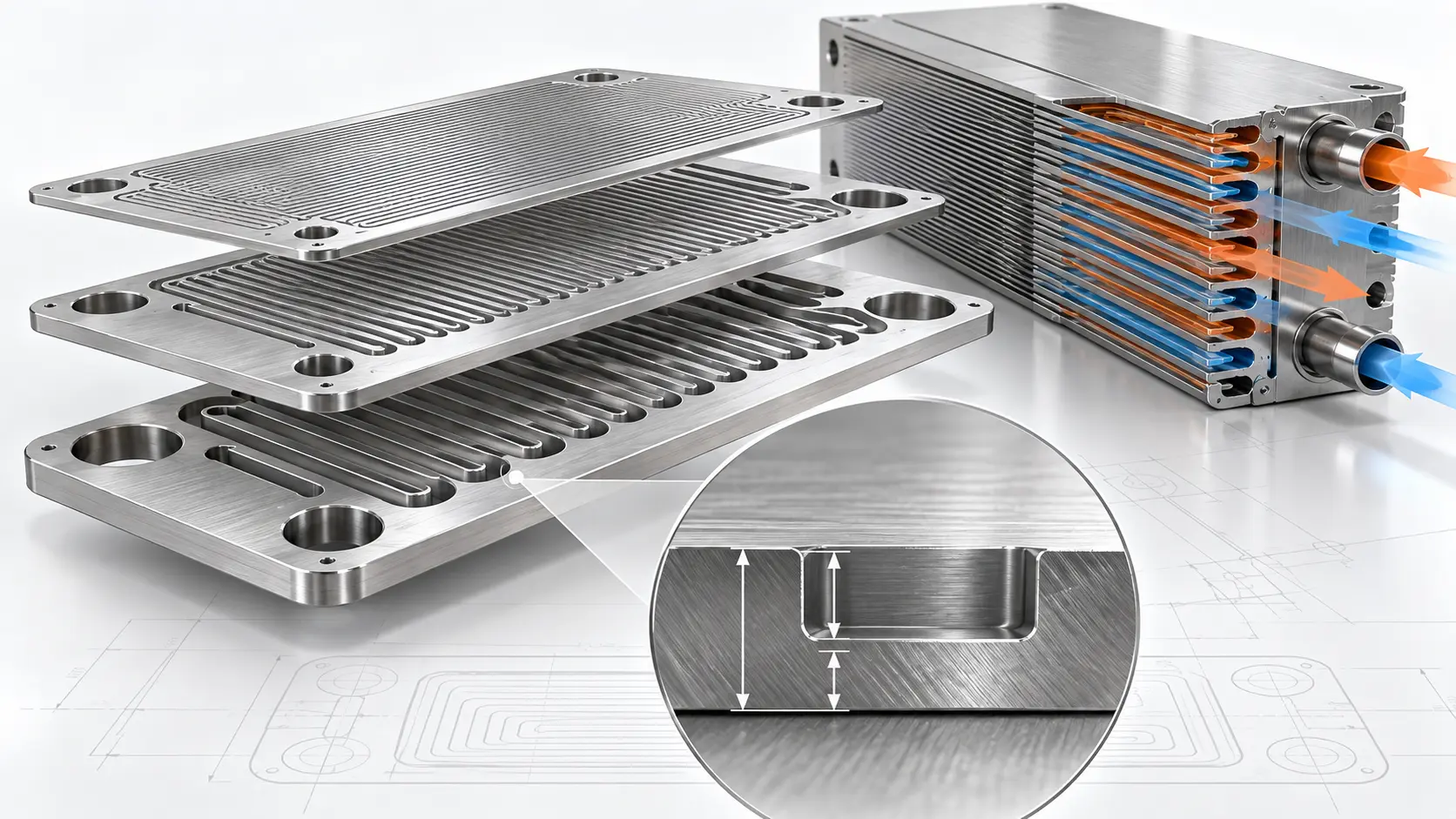
Plate heat exchangers use multiple metal plates to create separate channels. Ports distribute the fluids, while gaskets, brazing or welding seal the channels. Gasketed units can be opened for cleaning or plate replacement.
Corrugated plates increase surface area and change fluid motion. However, plate pattern, channel count and velocity also influence pressure drop. Adding plates does not automatically improve a system if the extra parallel channels reduce velocity too far.
Air-Cooled and Plate-Fin Heat Exchangers
Air-cooled exchangers use fans to move ambient air across finned tubes. They avoid cooling-water demand but require space and fan power.
Plate-fin exchangers pack plates and extended surfaces into a compact core. Small passages require control of cleanliness, drainage and fouling.
Printed Circuit and Microchannel Heat Exchangers
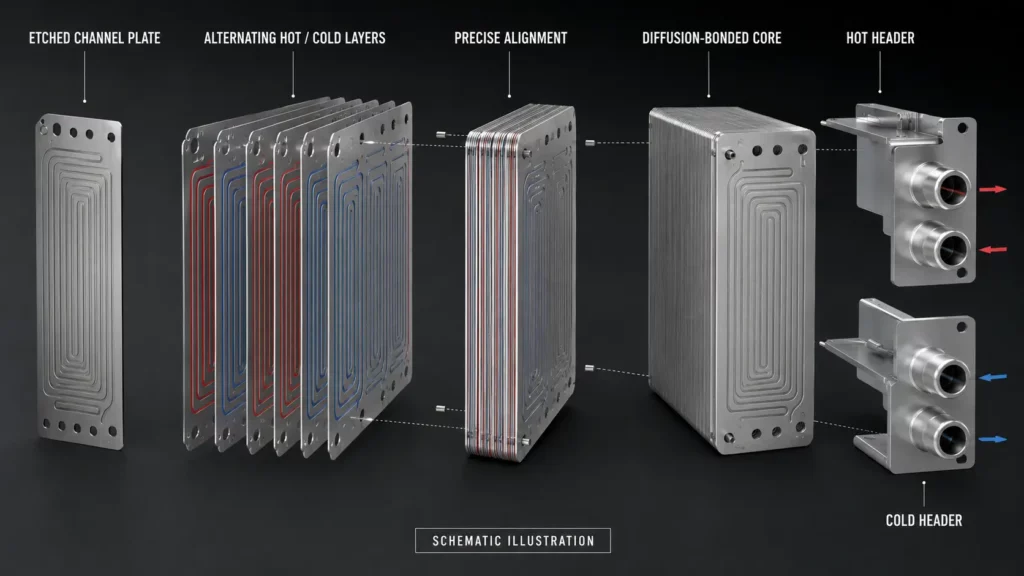
Printed circuit heat exchangers, or PCHEs, use stacked metal plates containing small flow channels. The Singapore NEA describes printed-circuit units as compact exchangers made from stacked etched plates and diffusion bonding. Because channel width, depth, spacing and distribution influence both flow resistance and heat transfer, similar flow field design principles are also important when developing etched flow plates.
Alfa Laval uses photochemically etched channels and diffusion bonding in PCHE cores for applications including LNG processing, hydrogen precooling and supercritical-CO₂ systems. These are product-specific capabilities, not universal PCHE limits.
| Type | Main strength | Main design concern | Typical use |
|---|---|---|---|
| Double-pipe | Simple construction | Low area density | Small process duties |
| Shell-and-tube | Strong, serviceable construction | Size and shell-side flow complexity | Chemical and power plants |
| Plate | Compact, accessible heat-transfer area | Gaskets, pressure drop and narrow channels | HVAC, food and district heating |
| Air-cooled | No cooling-water circuit | Space, fan power and ambient conditions | Refineries and gas cooling |
| Plate-fin | High area density | Cleanliness and small passages | Aerospace and cryogenic systems |
| PCHE | Compact, complex channel networks | Flow distribution, fouling and joining quality | Hydrogen, LNG and advanced energy systems |
Sources: ASHRAE, Ipieca, Singapore NEA and U.S. Department of Energy.
Which Parts Control Heat Exchanger Performance?
The heat-transfer surface may be a tube, plate, fin or microchannel wall. Shells, headers and nozzles contain and distribute fluids; tube sheets locate tubes; gaskets or permanent joints seal plate channels.
Baffles have two linked jobs in shell-and-tube equipment: they support tubes and direct shell-side flow. Common flow-deflecting designs include segmental, disc-and-doughnut, helical and rod arrangements. Poor flow control can create bypass paths or low-velocity zones, while aggressive redirection can increase pressure loss.
In compact assemblies, manifold and distribution plates divide incoming fluid among many passages. Flow maldistribution can reduce heat-transfer and pressure-drop performance. (U.S. Department of Energy OSTI)
How Is Heat Exchanger Performance Evaluated?
Key measures include heat duty, overall heat-transfer coefficient, approach temperature, effectiveness and pressure drop. Performance trends can reveal degradation more clearly than a single reading.
Fouling adds thermal resistance to the heat-transfer surface. Deposits can reduce heat transfer, restrict passages and increase the energy needed to maintain the required duty. Cleaning becomes an economic decision when the cost of lost performance exceeds the cost and disruption of maintenance.
Design check: More turbulence is not automatically better. A surface that raises the fluid-side heat-transfer coefficient may also increase pressure drop, erosion risk or pumping demand. (ASHRAE)
What Materials Are Used?
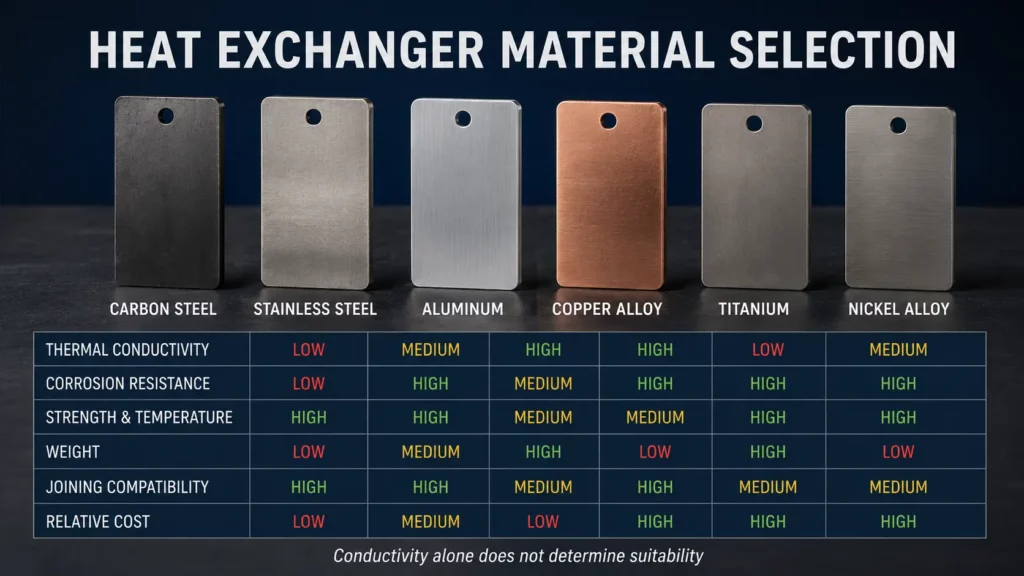
Material selection starts with the fluids and operating conditions. The metal must tolerate design temperature, pressure and corrosion while remaining compatible with fabrication and joining.
Common options include carbon steel, stainless steel, aluminum, copper alloys, titanium and nickel alloys. High conductivity alone does not make a material suitable if corrosion, strength, temperature or joining requirements are not met. For etched plate designs, engineers should also verify whether the selected alloy is compatible with the photochemical etching materials and process window.
Where Are Heat Exchangers Used?
Heat exchangers appear in HVAC and refrigeration as evaporators, condensers and liquid coolers. Industrial systems use them for reactor temperature control, feed preheating, product cooling, steam condensation and energy recovery.
Food processes may prioritize cleanability; oil, gas and chemical plants may emphasize pressure containment and corrosion; aerospace and electronics often impose tighter space and weight limits.
A Pressure-Drop Versus Heat-Duty Trade-Off
Increasing velocity or adding smaller flow passages can improve convection, but it can also increase pressure loss. Consider two hypothetical channel designs operating with the same 8 m² area and a 50 K LMTD:
| Design | Assumed UU | Calculated duty | Pressure drop | Hydraulic power at 0.005 m³/s |
|---|---|---|---|---|
| Wider channel | 0.8 kW/(m²·K) | 320 kW | 35 kPa | 0.175 kW |
| Narrower channel | 1.0 kW/(m²·K) | 400 kW | 70 kPa | 0.350 kW |
The narrower-channel concept raises the calculated heat duty by 25%, but it doubles the pressure drop and the theoretical hydraulic power requirement before pump efficiency is considered. It may be preferable when footprint is the controlling constraint, but unsuitable when pump head, erosion risk, fouling or operating cost governs the design.
This example illustrates why channel width and pattern density cannot be optimized from heat-transfer area alone. Thermal performance, pressure loss, cleanability and manufacturability must be evaluated together.
How Should Engineers Select a Heat Exchanger?
No single exchanger type is best for every duty. The following table should be used as a screening tool rather than a substitute for thermal and mechanical design.
| Operating condition | Starting point for evaluation | Use caution with | Main decision reason |
|---|---|---|---|
| Clean liquids and close temperature approach | Gasketed or welded plate exchanger | Simple parallel-flow units | High area density and favorable counterflow temperature profile |
| High pressure or high temperature | Shell-and-tube or qualified diffusion-bonded compact exchanger | Gasketed units beyond gasket limits | Pressure containment, code compliance and joint qualification |
| Dirty, viscous or solids-bearing fluids | Shell-and-tube, spiral or wide-gap plate design | Narrow microchannels | Fouling, blockage risk and cleaning access |
| Gas-to-liquid or ambient-air cooling | Finned-tube air cooler or crossflow coil | Unfinned compact liquid exchangers | Low gas-side heat-transfer coefficient requires extended area |
| Severe footprint or weight constraint | Brazed plate, plate-fin or qualified compact exchanger | Large conventional shells | High surface-area density |
| Frequent mechanical cleaning required | Removable-bundle shell-and-tube or gasketed plate | Permanently bonded channel cores | Access to heat-transfer surfaces |
| Multiple cryogenic process streams | Plate-fin or specially engineered compact exchanger | Basic double-pipe equipment | Multi-stream integration and compactness |
| Small duty or simple pilot system | Double-pipe exchanger | Complex custom cores | Low design complexity and easier fabrication |
The final decision still requires verified temperatures, flow rates, fluid properties, allowable pressure drop, fouling allowance, corrosion compatibility, cleaning method and applicable pressure-equipment code.
Where Does Photochemical Etching Fit?
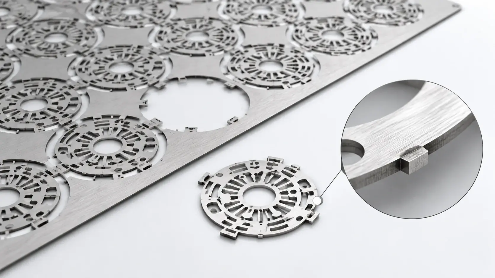
Photochemical etching is best evaluated as a method for producing thin, flat metal layers containing repeated channels, apertures, distribution features or identification marks. Potential heat-transfer applications include channel plates, separator plates, manifold layers, shims and selected cold-plate components. It is not a substitute for thermal design, joint qualification or pressure-vessel validation.
TMNetch publishes the following process information on its current Photo Etching service page and technical capability guide:
| Capability item | Published information | Engineering interpretation |
|---|---|---|
| Metals | Stainless steel, copper, brass, phosphor bronze, beryllium copper, aluminum, titanium, nickel alloys, molybdenum and other etchable metals | Exact alloy, temper and chemical compatibility require drawing review |
| General processing thickness | 0.02–1.5 mm, depending on material and geometry | Thicker or highly perforated sheets may require a specific feasibility review |
| Minimum feature | Down to 0.05 mm for suitable geometries | Not a universal minimum hole, web or spacing value |
| Dimensional tolerance | Critical dimensions as tight as ±0.025 mm; product pages commonly state ±0.03 mm | Tolerance depends on thickness, alloy, feature density and measurement method |
| Double-sided processing | Photoresist and patterning can be applied on both sides | Front-to-back registration must be included in the drawing requirements |
| Half-etching | Channels, bend lines, logos and recessed features are supported | Required depth, remaining thickness and depth tolerance must be reviewed separately |
| Maximum size | One TMNetch acid-etching process guide lists parts up to 1500 × 600 mm | Usable area may be smaller after allowing for alloy, border, flatness and pattern constraints |
| Inspection | CMM and dimensional quality checks are listed; optical measurement may be used for small features | Critical dimensions, sampling plan and report format should be defined in the RFQ |
| Quality system | ISO 9001:2015-certified facility | ISO 9001 controls the quality-management system; it does not certify pressure-vessel design |
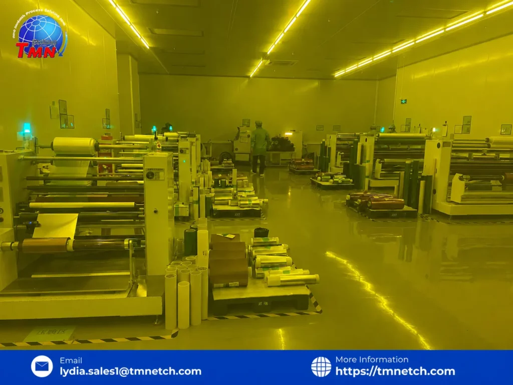
| Production resources | Four automated 20-metre etching lines, 19 supporting systems and published capacity up to 1,800 m²/day | Actual throughput depends on material, panel utilization, inspection and secondary processing |
Which Standards May Apply?
The governing standard depends on the exchanger, industry and jurisdiction. ASME BPVC Section VIII addresses pressure-vessel construction. TEMA covers shell-and-tube mechanical design and terminology. API lists API 660 for shell-and-tube exchangers and API 661 for air-cooled units in petroleum-related service. ISO 15547-1 covers plate-and-frame exchangers for petroleum, petrochemical and natural-gas industries.
Project specifications must identify which code, edition, certification and inspection requirements apply.
Frequently Asked Questions
Is a radiator a heat exchanger?
Yes. A vehicle radiator transfers heat from engine coolant to air moving across its tubes and fins, making it an air-cooled, crossflow heat exchanger.
Why is counterflow usually more effective than parallel flow?
Counterflow maintains a more consistent temperature difference along the exchanger. This can provide a larger effective thermal driving force, although the best configuration still depends on pressure drop and mechanical constraints.
Can heat exchanger plates be made by chemical etching?
Yes, selected thin plates can contain photochemically etched channels or distribution features. Suitability depends on material, thickness, channel geometry, joining method and pressure requirements; thick structural and pressure-bearing parts usually need other processes.
Conclusion
A heat exchanger works because a temperature difference drives energy from a hot stream to a cold stream. Its performance depends on the complete system: flow arrangement, surface geometry, area, pressure drop, fouling, materials and maintenance.
In compact plate and printed-circuit designs, the patterned plate becomes part of the thermal and hydraulic system. This creates a role for precision etched metal parts with channels, manifolds and repeated flow features after operating conditions and assembly methods are defined.
If you are evaluating an etched heat-exchanger plate, manifold layer or flow-distribution component, submit the drawing and operating requirements through the TMNetch contact page. A useful review package should identify the alloy, thickness, critical features, half-etch requirements, annual volume, inspection standard and intended joining process. Thermal sizing and pressure-boundary approval should remain with the qualified exchanger designer.