
Fuel cell stack design is not simply a matter of connecting more cells to achieve higher voltage. Engineers must balance cell count, active area, reactant distribution, pressure drop, heat removal, sealing, compression, and manufacturability so that every cell operates as uniformly as possible across the intended load range.
A practical design process therefore starts with the required stack voltage, power, current density, operating conditions, and packaging limits. From there, engineers can size the stack, design manifolds and flow fields, select an appropriate cooling strategy, control compression, and validate the complete system through simulation and prototype testing.
This guide explains the main engineering decisions involved in fuel cell stack design and development, with particular attention to flow distribution, thermal management, compression, mechanical integrity, and validation. If you first need a cell-level explanation, see our guide to how a fuel cell works step by step and our overview of PEM fuel cell structure and key components.
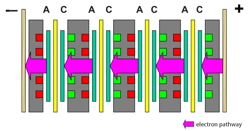
Individual fuel cells produce relatively low voltage, so multiple cells are typically connected in series to form a fuel cell stack capable of delivering a usable system voltage. The required cell count therefore depends partly on the target stack voltage and expected operating voltage per cell. Additionally, this stacking method allows for more efficient use of fuel and improves the overall efficiency of the system. In the design of the Fuel Cell Stack, optimizing current distribution and thermal management is key, as it can reduce energy loss and enhance overall performance.
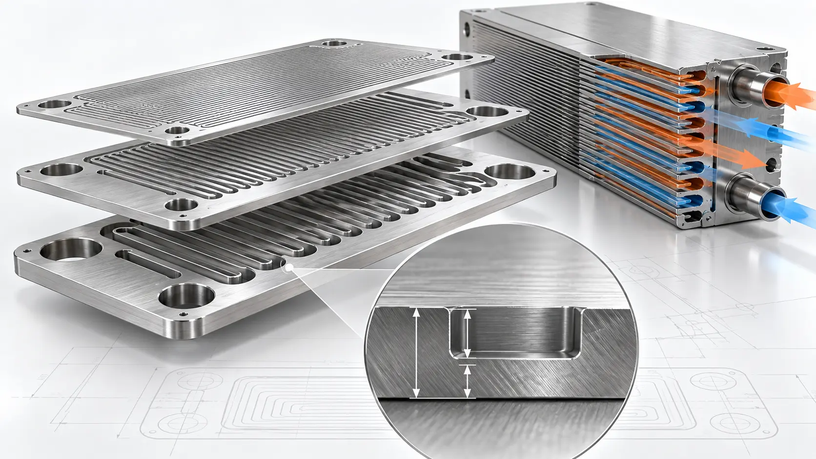
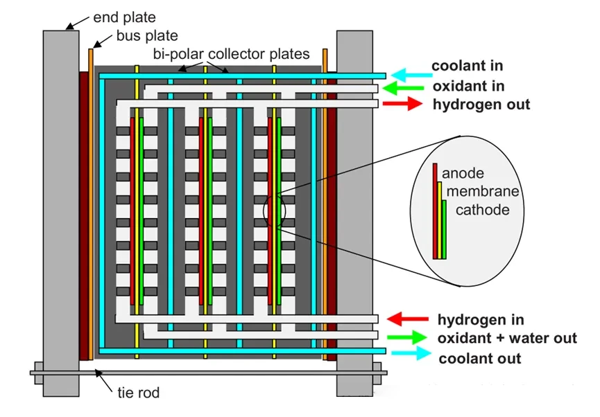
The main components of a fuel cell stack include the membrane electrode assembly (MEA), bipolar plates, current collectors, end plates, and gaskets. Among these parts, the bipolar plate performs several key functions in the fuel cell stack, including gas distribution, current conduction, water management, heat transfer, and mechanical support. The entire Fuel Cell Stack is held together by tie rods, bolts, or straps to ensure structural integrity.
Key Takeaways
- Start with system requirements, not cell geometry. Target voltage, power, current density, operating temperature, reactant pressure, service life, and packaging constraints determine the basic stack architecture.
- Cell count and active area should be sized together. Voltage largely determines the number of cells in series, while required current and target current density influence the necessary active area.
- Uniform reactant distribution is a stack-level priority. Manifold geometry and individual-cell pressure drop must be balanced to reduce cell-to-cell flow variation.
- Flow-field design is a trade-off between transport and resistance. Channel geometry affects reactant distribution, pressure drop, water removal, electrical contact, heat transfer, and mechanical support.
- Cooling must control both average temperature and local temperature gradients. Liquid, air, edge, and phase-change cooling strategies offer different balances of heat-removal capacity, packaging complexity, and parasitic energy use.
- Compression should be uniform rather than simply high. Too little pressure can increase contact resistance and leakage risk, while excessive compression can deform the gas diffusion layer and restrict gas and water transport.
- Simulation should support—not replace—physical validation. CFD can assess flow and thermal distribution, while FEA can evaluate end-plate deformation, gasket compression, and contact-pressure uniformity.
- The design should be validated as a complete system before production. Polarization performance, individual-cell voltage, pressure drop, leakage, temperature distribution, contact pressure, electrical resistance, and water management should all be checked before final dimensions are frozen.
Practical design sequence:
Define requirements → size the stack → design reactant distribution → design cooling and compression → simulate → prototype → test → refine.
Define Fuel Cell Stack Design Requirements Before Sizing
A fuel cell stack should be sized from system requirements rather than from a preferred cell format. Before selecting the number of cells, active area, manifold geometry, or cooling method, engineers should define the required electrical output and operating conditions.
The main design inputs include:
| Design Input | Why It Matters |
|---|---|
| Target stack power | Determines the required combination of voltage and current |
| Target stack voltage | Establishes the approximate number of cells in series |
| Target current density | Helps determine the required active area |
| Operating temperature | Affects membrane performance, cooling, sealing, and material selection |
| Reactant pressure and stoichiometry | Influence manifold sizing, pressure drop, and gas distribution |
| Size and weight limits | Constrain cell area, plate thickness, end plates, and packaging |
| Service life | Affects material, coating, sealing, and compression decisions |
| Operating profile | Determines whether the stack is optimized for steady load, variable load, or frequent start-stop cycles |
These parameters are interdependent. A design optimized only for peak power may require a larger active area or higher current density, but this can increase thermal load, reactant demand, pressure drop, and water-management difficulty.
The design point should therefore come from the expected operating range rather than from maximum theoretical performance. Once the target voltage, power, current density, and packaging limits are defined, engineers can estimate the required cell count and active area before moving into detailed manifold, cooling, and compression design.
1.1 Uniform Distribution of Reactants to Each Single Battery
Since the performance of Fuel Cells is highly sensitive to the flow rate of reactants, it is crucial to ensure that each Single Battery within the Fuel Cell Stack receives approximately the same reactant flow. This uniformity can be achieved by supplying reactants to each Single Battery in the Fuel Cell Stack through parallel external or internal manifolds. In practical applications, internal manifolds are more commonly used in PEM fuel cell designs, primarily because they offer better sealing performance and greater flexibility in airflow configuration.
The size of the manifolds that deliver and collect unused gases must be properly designed. The cross-sectional area of the manifolds determines the gas flow rate and pressure drop. As a general rule, the pressure drop through the manifolds should be an order of magnitude lower than the pressure drop across each Single Battery to ensure that the reactant flow is uniformly distributed to each Single Battery.
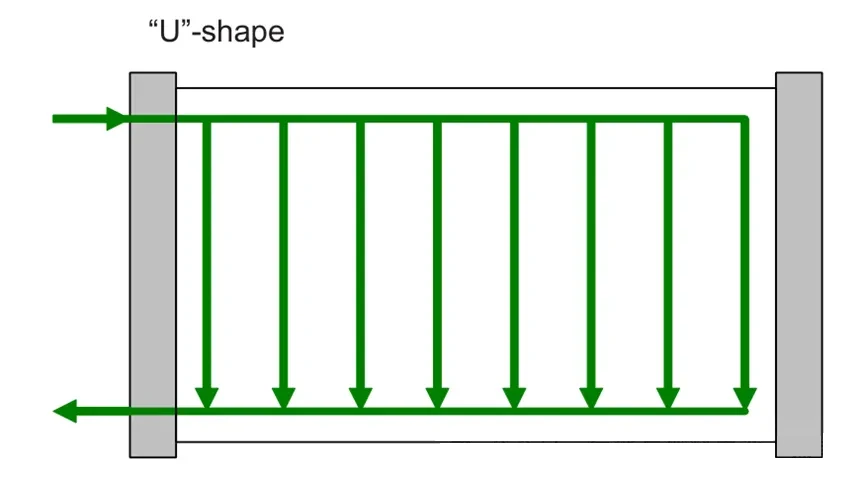
The airflow pattern in the Fuel Cell Stack can be configured in either a U-shape or Z-shape. In the U-shape configuration, the inlet and outlet are located on the same side of the Fuel Cell Stack, with the flow directions opposite to each other (as shown in the diagram).
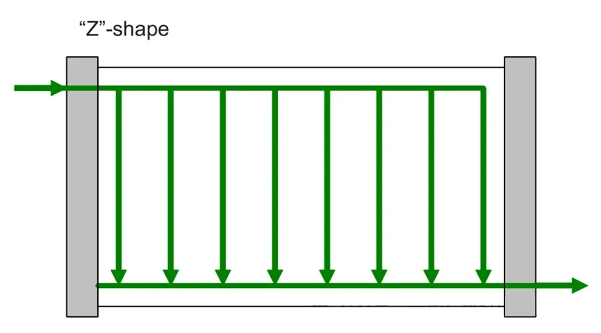
In the Z-shape configuration, the inlet and outlet are located on opposite sides of the Fuel Cell Stack, with the flow directions parallel to each other (as shown in the diagram).
Both configurations can ensure that reactants are uniformly distributed to each Single Battery, provided the dimensions are appropriately designed.
In both U-shape and Z-shape configurations, the flow of reactants within each Single Battery is parallel. However, a Z-shape configuration can also be used where the Single Batteries in the Fuel Cell Stack are arranged in segments with parallel gas supply but connected in series. In this case, the gas exiting the first section is fed into the Single Batteries of the second section (as shown in the diagram).
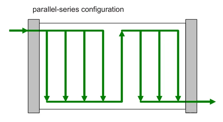
This parallel-series arrangement allows all cells in the Fuel Cell Stack to operate at a higher stoichiometric ratio, making it more effective than a purely parallel gas supply method.
1.2 Uniform Distribution of Reactants Within Each Single Battery
Once the reactant gases enter a single cell, they must be distributed across the active area with a controlled pressure drop. Channel geometry, manifold position, water removal, thermal balance, and manufacturing accuracy must be evaluated together. See our fuel cell flow field design guide for a more focused discussion of these variables. This is typically achieved by designing specific flow field patterns or using channels with porous structures. The following are key factors in flow field design:
1.2.1 Flow Field Shape
The shape and size of the flow field vary depending on the location of the inlet and outlet manifolds, the requirements of the flow field design, thermal management needs, and manufacturing constraints. Common flow field shapes include square and rectangular, but circular, hexagonal, and octagonal shapes are also used.
1.2.2 Flow Field Direction
The direction of the flow field and the positioning of the inlet and outlet manifolds are crucial, especially for managing condensation. While the effect of gravity on reactant gases is negligible, it does influence the movement of water. In practical operation, the flow field direction needs to account for operating conditions as well as water condensation after shutdown.
1.2.3 Channel Configuration
Various bipolar plate channel structures are used in PEM fuel cells. Each configuration creates a different balance between reactant distribution, pressure drop, water removal, current density, and manufacturing complexity. At stack level, the key question is not which flow field is universally best, but whether its pressure-drop characteristics are compatible with the manifold and operating range.
| Flow Field | Main Advantage | Main Trade-off | Typical Use |
|---|---|---|---|
| Single serpentine | Strong water removal | Higher pressure drop | Small/medium active area |
| Multi-serpentine | Lower pressure loss | Risk of uneven channel distribution | Larger active area |
| Interdigitated | Strong convection through GDL | Higher pumping demand | High mass-transfer demand |
| Biomimetic/fractal | Potentially uniform distribution | Greater design/manufacturing complexity | Advanced designs |
See our full Fuel Cell Flow Field Design Guide.
1.2.4 Shape, Size, and Spacing of Channels
Flow channel geometry is affected by both performance requirements and manufacturing limits. Channel depth, wall profile, material thickness, tooling cost, coating needs, and production volume can determine whether etching, stamping, hydroforming, or machining is suitable. Compare these options in our bipolar plate manufacturing process guide. For projects moving from flow-field design into sourcing, custom metal bipolar plates should be evaluated against the required material, channel geometry, channel depth, coating, tolerance, and expected production volume.
However, the geometry of the channels significantly impacts the accumulation and drainage of water. In channels with a rounded bottom, condensed water tends to form a water film at the base, whereas in tapered channels, it is more likely to form small droplets, as illustrated below:
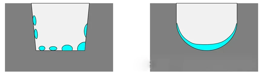
How Channel Geometry Changes Stack Performance
| Design Change | Potential Benefit | Trade-off |
|---|---|---|
| Wider channel | Better gas access | Less rib contact/support |
| Narrower channel | Better mechanical support | Higher flow resistance |
| Wider land/rib | Better electrical/thermal conduction | Less direct gas access |
| Deeper channel | Lower pressure drop | Thicker plate / manufacturing constraints |
1.3 Cooling of the Fuel Cell Stack
To maintain the optimal operating temperature of Fuel Cells, it is crucial to effectively dissipate the heat generated during electrochemical reactions. In automotive PEMFC systems, thermal management must reject the low-temperature waste heat generated by the fuel cell stack, which makes cooling-system design an important part of stack and system development. The diagram below illustrates several different thermal management strategies.
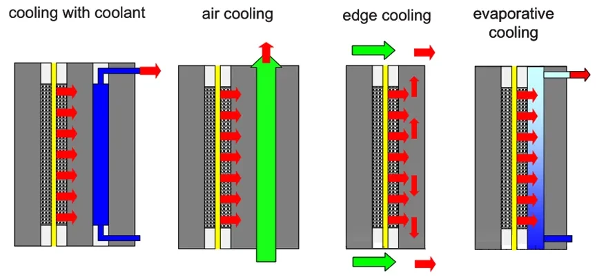
(Various cooling strategies for Single battery/Fuel cell stack)
Fuel Cell Stack Cooling Methods Compared
| Cooling Method | Heat Removal | Stack Complexity | Main Limitation | Best Fit |
|---|---|---|---|---|
| Liquid cooling | High | Higher | Pump/manifold complexity | High-power stacks |
| Air cooling | Moderate | Lower | Limited heat capacity | Lower-power stacks |
| Edge cooling | Limited | Low | Long heat-conduction path | Compact low-power stacks |
| Phase-change cooling | High potential | Specialized | Control complexity | Specific architectures |
1.3.1 Cooling by Flowing Coolant Between Cells
The coolant can be deionized water, antifreeze, or air. The cooling system can be arranged between each Single battery, between pairs of Single batteries (where the cathode of one battery is adjacent to the anode of another and closely positioned to the cooling device), or between groups of Single batteries (which is only suitable for low power density applications, as this arrangement might cause the central Single batteries to overheat). The uniform distribution of coolant can be achieved through a manifold system similar to that used for the reactant gases. If air is used as the coolant, a plenum can ensure even distribution.
1.3.2 Cooling Using Coolant at the Edges of the Active Area
In this method, heat is conducted through the Bipolar Plate and transferred to the coolant (usually air). To ensure uniform temperature distribution within the active area, the Bipolar Plate must have good thermal conductivity. However, the heat transfer area at the edge surfaces might be insufficient, so fins may be required to enhance heat dissipation. Although this cooling method simplifies the Fuel cell stack structure and reduces the number of components, it is generally suitable for applications with low power output due to the limitations of heat conduction.
1.3.3 Phase Change Cooling
The phase change coolant can be water or other phase change materials. Using water as the coolant can simplify the Fuel cell stack design, as the anode and cathode chambers already utilize water as the cooling medium. This method effectively absorbs and transfers heat through the phase change process of the coolant.
1.3.4 Cooling Through Reaction Air
In the cathode chamber, air flows at a stoichiometric ratio exceeding that required for oxygen, thereby providing cooling. In theory, this flowing air can be used as a coolant, but to effectively remove the heat generated by the Fuel cell stack, the airflow rate must be significantly increased. The required stoichiometric ratio can be determined by a simple heat balance calculation, ensuring that the heat generated by the Fuel Cells equals the heat carried away by the air.
1.4 Compression Methods for Fuel Cell Stacks
In a Fuel cell stack, all components such as the Membrane Electrode Assembly (MEA), Gas Diffusion Layer, and Bipolar Plate must be held together with appropriate contact pressure to prevent reactant leakage and minimize interfacial contact resistance. The usual approach involves placing the stacked components between two end plates and securing them with tie rods, which can either surround the outside of the stack or, in some cases, pass through the interior of the stack. In addition to tie rods, other compression and fastening devices like snap-fit shrouds or straps may also be used.
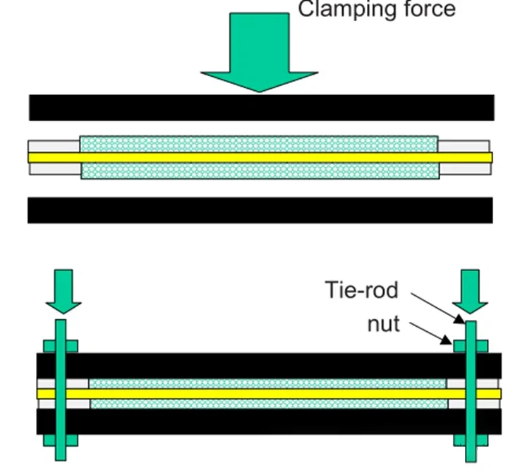
The clamping force must meet the following requirements: first, it should be strong enough to compress the gaskets, then compress the Gas Diffusion Layer, and finally resist the internal operating pressure. The pressure required to prevent interlayer leakage depends on the material and design of the gaskets. Fuel Cell gaskets come in various materials, ranging from rubber to proprietary polymers. Designs also vary among manufacturers; gaskets can be flat or shaped, and they may be separate components or integrated into the Bipolar Plate or Gas Diffusion Layer.
If excessive force is applied around the perimeter, it may cause the end plates to bend, which can affect the compression in the active area, as shown in the diagram below:
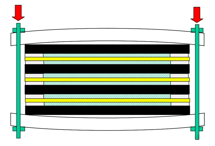
The distribution of the clamping force can be monitored using pressure-sensitive film (which only records the maximum force applied) or pressure-sensitive electronic pads, allowing real-time monitoring during assembly. To prevent bending of the end plates, the design must ensure that the end plates have sufficient rigidity. Additionally, end plates with hydraulic or pneumatic pistons can be used to apply uniform pressure across the entire active area. Another design option is to pass tie rods through the center of the end plates and arrange the flow field around the tie rods.
Contact pressure affects gas sealing, GDL compression, and interfacial contact resistance. The required pressure depends on the GDL, gasket, plate material, surface condition, and stack design. For metallic plates, etching quality and coating performance can also affect corrosion resistance and electrical contact behavior. The Gas Diffusion Layer is compressible, so the required compression must be determined through the cell design. This can be achieved by precisely matching the thickness of the hard stops or grooves on the Gas Diffusion Layer, gaskets, and Bipolar Plates.
It is important to note that if the Gas Diffusion Layer is over-compressed, it may collapse and lose its primary function—permeability to gases and water. The optimal compression ratio should be determined experimentally to ensure the effective functionality of each gas diffusion medium.
Simulation and Prototype Validation Before Finalizing the Stack
Fuel cell stack design should be validated before production tooling or final component dimensions are frozen. Electrical sizing alone cannot show whether hundreds of flow channels, sealing interfaces, cooling paths, and compressed layers will operate uniformly across the complete stack.
CFD for Flow and Thermal Validation
Computational Fluid Dynamics (CFD) can be used to evaluate whether the manifold and flow-field design distributes reactants and coolant uniformly across the stack.
Typical CFD checks include:
- cell-to-cell flow distribution,
- manifold pressure variation,
- channel pressure drop,
- hydrogen and oxygen distribution,
- water transport,
- coolant distribution,
- local temperature differences.
A design may provide the required total gas flow while still producing unequal flow between individual cells. This is why stack-level flow uniformity should be evaluated together with manifold dimensions and individual-cell pressure drop.
CFD should support engineering decisions rather than replace physical testing. Boundary conditions and material properties should reflect the intended operating conditions, and simulation results should be compared with prototype measurements whenever possible.
FEA for Compression and Mechanical Validation
Finite Element Analysis (FEA) is useful for evaluating mechanical behavior during stack assembly.
It can help identify:
- end-plate deflection,
- uneven contact pressure,
- gasket compression,
- local stress in bipolar plates,
- variation in MEA and GDL compression.
Insufficient compression can increase contact resistance or create leakage paths. Excessive compression can deform the gas diffusion layer and reduce gas and water transport. The target is therefore not maximum clamping force, but a sufficiently uniform pressure distribution across the active area.
Validate the Design with a Physical Prototype
Simulation should be followed by prototype testing under representative operating conditions. The validation plan should check both overall stack performance and cell-to-cell consistency.
| Validation Item | What It Reveals |
| Polarization curve | Overall voltage-current performance |
| Individual cell voltage | Cell-to-cell uniformity and local abnormalities |
| Reactant pressure drop | Flow resistance and manifold behavior |
| Leakage test | Gas and coolant sealing integrity |
| Temperature distribution | Cooling effectiveness and local hot spots |
| Contact pressure | Compression uniformity |
| Electrical resistance | Contact and conductive losses |
| Water-management behavior | Flooding or membrane dry-out risk |
The results should feed back into manifold geometry, cooling design, compression, sealing, and component tolerances before the stack moves to production.
This creates a practical development loop:
Define requirements → size the stack → design flow, cooling, and compression → simulate → prototype → test → refine.
Detailed electrochemical test procedures can then be handled in a dedicated PEMFC performance-testing article rather than expanded inside the stack design guide.
Summary:
From a structural perspective, the Fuel cell stack is a relatively simple device, as it consists of multiple Single batteries stacked in series. Each Single battery is composed of a Bipolar Plate, Gas Diffusion Layer, catalyst layer, and proton exchange membrane, forming a straightforward layered structure that appears easy to achieve. However, from a functional standpoint, it is a highly complex device. The Fuel cell stack must effectively manage gas flow, heat transfer, and current distribution within a confined space while ensuring uniform distribution of reactants and products and maintaining good sealing and mechanical strength under varying operating conditions.
To meet these diverse requirements, the design of the Fuel cell stack involves precise material selection, optimization of geometric construction, and sophisticated thermal management and compression strategies. Each component must not only achieve the optimal balance in size and spacing but also ensure sustained high-efficiency electrochemical reactions during long-term operation. Particularly in controlling the contact pressure between the Gas Diffusion Layer and Bipolar Plate, as well as optimizing the cooling system, extensive experimentation and validation are required to guarantee the stability and efficiency of the entire system.
Thus, although the basic construction of a Fuel cell stack may appear simple, the underlying design and engineering work is extremely complex and precise. Every design choice can affect stack performance, durability, pressure loss, sealing, and thermal balance. Bipolar plate geometry is only one part of the complete stack design, but it directly affects gas distribution, water removal, current conduction, and manufacturability.
If your project requires custom metal flow channels, review TMNetch’s custom metal bipolar plate manufacturing capabilities before submitting your drawing for technical review.
Read more:
PEMFC: Detailed Composition and Performance Testing Methods of Single Cells
Detailed Explanation of the Structure and Principle of Proton Exchange Membrane Fuel Cells
The influence of bipolar plate structure on fuel cell performance
ORR reaction mechanism of Proton exchange membrane fuel cells