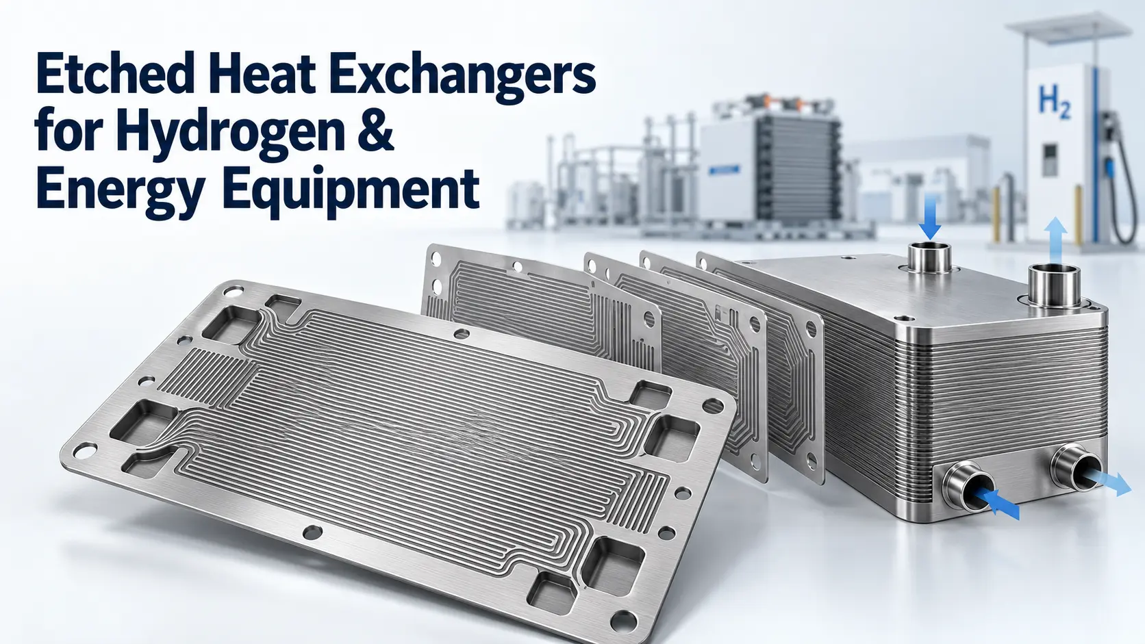

Yes. Chemical etching can manufacture selected flat heat exchanger plates with partial-depth channels, through-holes, ports, manifolds and alignment features. It is especially relevant to printed circuit heat exchanger plates, microchannel layers and compact cold-plate components. However, the etched plate must still be joined and validated as part of a complete heat exchanger; etching alone does not create a pressure-rated assembly.
For an existing plate drawing, a chemical etching services review can assess the material, thickness and channel geometry. Thermal sizing, joining qualification and pressure approval remain separate tasks.
Key Takeaways
- Chemical etching suits complex patterns in flat metal sheet, not every heat exchanger plate.
- Partial etching forms open channels; through-etching forms ports, holes and outside profiles.
- Channel width, depth, ligament width and remaining wall must be designed together.
- Diffusion bonding, brazing or welding is needed to turn open plates into sealed passages.
- A plate’s etching tolerance does not establish the pressure rating of the finished exchanger.
What Does Chemical Etching Mean for a Heat Exchanger Plate?
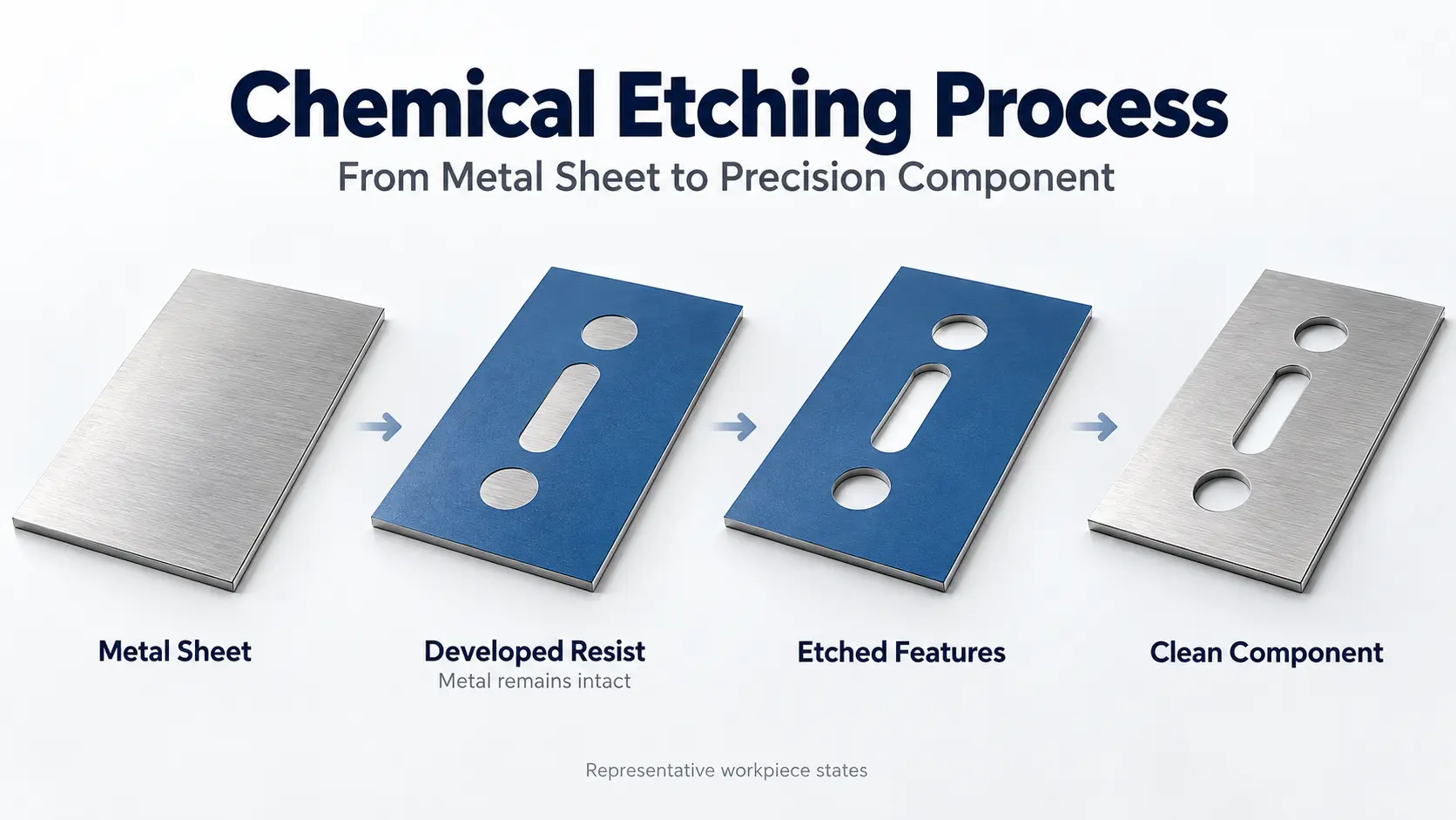
Here, chemical etching means photochemical etching, also called photochemical machining or photo etching. Photoresist protects selected areas while an etchant removes exposed metal. Partial etching creates recessed paths; through-etching creates openings and the plate outline. A photo etching process guide explains the production stages.
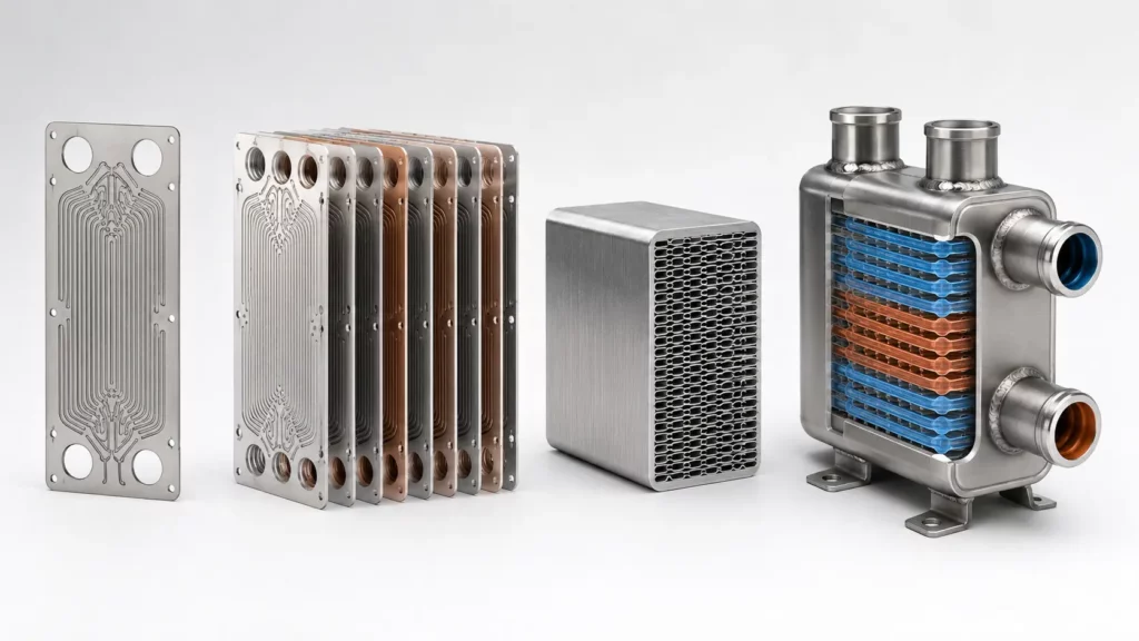
Three manufacturing levels must remain separate: an open etched plate, a joined core with sealed passages, and a complete exchanger with headers, mechanical calculations and required tests.
Idaho National Laboratory describes microchannel exchanger plates that were etched and then diffusion welded into all-metal cores. Bonded core blocks could then be welded together to provide the required flow capacity. This sequence shows exactly where chemical etching ends and pressure-equipment manufacturing begins.
Which Heat Exchanger Plates Can Be Made by Chemical Etching?
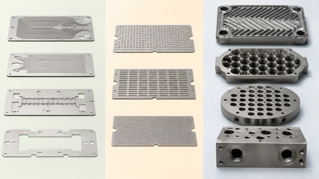
The strongest candidates are flat layers whose function comes from a two-dimensional pattern or controlled recess.
| Component | Etching suitability | Main design boundary |
|---|---|---|
| Printed circuit heat exchanger flow plate | High | Channel depth, ligament and bonding area |
| Microchannel or cold-plate layer | High | Remaining wall and cover-plate joining |
| Manifold or distribution plate | High | Port alignment and flow distribution |
| Separator, shim or sealing layer | High | Flatness and sealing-land width |
| Thin perforated baffle or flow straightener | Conditional | Thickness, stiffness and operating load |
| Pressed herringbone plate | Low | Requires three-dimensional corrugation |
| Thick shell-and-tube baffle | Low | Tube support and structural loads |
| Tube sheet, end block or pressure shell | Very low | Thick sections, deep holes and pressure loads |
“Baffle” needs context. The ASHRAE Handbook states that shell-side baffles can support tubes and direct flow. A thin distributor may suit etching; a thick support baffle is not a simple etched sheet.
For a deeper discussion of small channels and layered cores, see photochemical etching for microchannel heat exchangers.
How Does Chemical Etching Form Channels, Ports and Manifolds?
Production begins with the alloy, thickness and CAD pattern. The sheet is cleaned, coated, exposed, developed and etched. The plate is then stripped, cleaned and inspected. One design can combine recessed channels, through-ports, alignment holes and its outside profile.
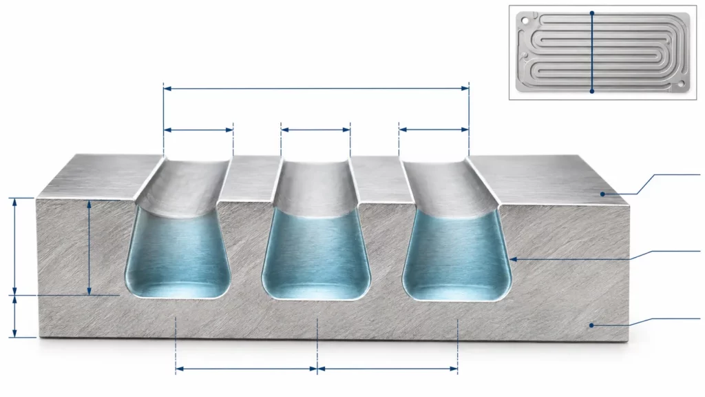
Chemical etching removes metal downward and sideways. This undercut can produce rounded or tapered walls rather than a milled rectangular section.
A study in Nuclear Engineering and Design found that concentration, temperature, spray pressure and time affected etching rate, lateral erosion and roughness. Its 0.5–2.0 mm stainless steel channels were experimental geometries, not universal supplier limits.
The drawing should define finished top width, bottom width, depth, pitch, ligament, remaining wall and measurement locations—not only the artwork opening.
What Plate Thickness, Channel Size and Tolerance Are Practical?
No single thickness or tolerance fits every plate. Deeper channels remove supporting material, while narrower ligaments reduce sealing and joining land. Thin plates may also become harder to handle and keep flat.
The dedicated TMNetch photo etching page currently lists a general material range of 0.02–1.5 mm, features down to 0.05 mm for suitable geometries and critical tolerances as tight as ±0.025 mm. TMNetch’s broader chemical etching capability page lists part sizes up to 600 × 1500 mm. These are general process envelopes, not guaranteed specifications for every heat exchanger plate.
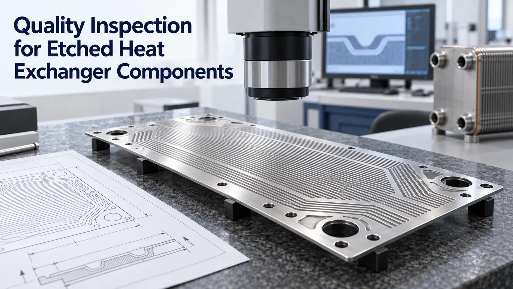
The supplier must still review alloy, depth, pattern density, flatness and inspection. A ±0.025 mm linear tolerance should not automatically cover depth, flatness and front-to-back registration. The photochemical etching tolerance guide explains the relationship with thickness and measurement method.
Which Metals Can Be Used for Etched Heat Exchanger Plates?
Material selection begins with both fluids, temperature, pressure, corrosion and thermal cycling. Etchability is only one condition; the grade must also remain suitable after joining.
| Material family | Why engineers evaluate it | Question that must be resolved |
|---|---|---|
| 316L stainless steel | Established use in etched and diffusion-bonded exchangers | Does the grade resist both fluids after the joining cycle? |
| Nickel alloys | Considered for selected high-temperature or corrosive duties | Which exact alloy and bonding procedure apply? |
| Titanium alloys | Considered for weight-sensitive or selected corrosive services | Can its surface and oxide condition be controlled during joining? |
| Aluminum alloys | Used where low mass and suitable thermal properties are important | Is the alloy compatible with the intended brazing or bonding route? |
| Copper alloys | Considered for compact thermal components and cold plates | Are strength, corrosion and joint properties adequate? |
The Nickel Institute recommends considering fluid chemistry, operation, maintenance and exchanger design together. Idaho National Laboratory has also studied etched and diffusion-bonded Alloy 617 plates, while noting that bond parameters and interfaces require characterization.
Etchability is a manufacturing-screening factor, not a material-selection criterion for service. The final grade must be selected against fluid chemistry, design temperature, pressure, corrosion allowance, fatigue duty, joining cycle, and the governing construction code.
TMNetch provides separate manufacturing information for stainless steel, titanium, aluminum, copper and nickel. Final approval should always use the exact grade and drawing.
How Are Etched Plates Joined into a Heat Exchanger Core?
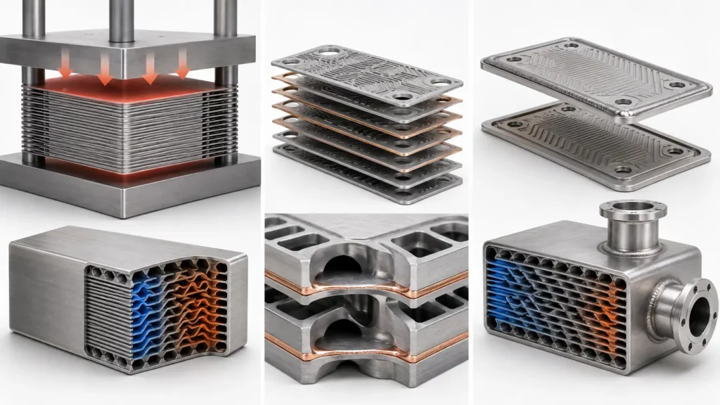
For many all-metal PCHE cores, diffusion bonding is the defining joining route. Other etched heat-transfer assemblies may instead use vacuum brazing, laser welding, TIG welding, gasketed construction, or another qualified joining method, depending on material, channel size, duty, and certification requirements. ISO/TR 25901-3, defines it as pressure welding using controlled contact, heat and time to produce diffusion across the interface. Surface preparation and the bonding cycle must suit the alloy and geometry.
Brazing introduces a filler metal that becomes liquid at the joint. In a small-channel core, filler flow must not obstruct the passages.
Conventional welding may join plate pairs, headers, nozzles or bonded blocks. Weld access, distortion and sealing length must be considered. The route depends on material, pressure, temperature and construction rules.
TMNetch publicly documents chemical etching and selected thin-plate welding work. Diffusion bonding, vacuum brazing or delivery of a complete pressure-rated exchanger should be stated as company capabilities only after the project scope and qualified supply route have been confirmed.
Can Chemically Etched Plates Be Used in a Pressure-Rated Heat Exchanger?
Yes, but the rating belongs to the completed exchanger. Mechanical design must address ligaments, remaining wall, material strength at temperature, joints, headers, corrosion allowance, thermal cycling and fatigue.
Standards must match the equipment. ISO 15547-1 covers gasketed, semi-welded and welded plate-and-frame exchangers. ISO 15547-2 covers brazed aluminum plate-fin exchangers for petroleum, petrochemical and natural-gas service.
Engineering boundary: Chemical etching defines the plate geometry. It does not establish the pressure rating, allowable temperature or certified service life of the final exchanger.
When Is Chemical Etching Not the Right Process?
Chemical etching is a flat-sheet process. Machining, drilling, forming, laser cutting or stamping may be better for thick sections, deep pockets, threads, vertical walls or deep corrugations. Thick tube sheets and load-bearing baffles also need other methods.
Etching also becomes more difficult when very small openings are combined with relatively thick material. More metal must be removed, while lateral undercut continues to widen the feature. TMNetch’s guide to photochemical etching limitations explains why feature size, thickness, depth and spacing must be reviewed together.
The exchanger duty can also rule out a design even when the plate is manufacturable. Permanently bonded narrow passages may be unsuitable for streams with particles, heavy fouling or a need for frequent mechanical cleaning. Heat exchanger selection must therefore consider both manufacturing feasibility and long-term operation.
What Information Should Be Included in an RFQ?
A useful RFQ includes alloy and temper, thickness, dimensions and quantity. The drawing should identify channel width, depth, pitch, ligament, remaining wall, ports, manifolds, alignment holes, flatness and critical tolerances.
Also provide the joining process, fluids, temperature, pressure, allowable pressure drop and inspection requirements. This lets the supplier identify manufacturing risks without assuming the complete thermal or pressure design.
TMNetch can review drawings for custom etched flow plates, distribution layers, shims and selected thin baffles. Submit the drawing and operating requirements through the TMNetch contact page for an initial manufacturability review.
Frequently Asked Questions
Can stainless steel heat exchanger plates be chemically etched?
Yes. Stainless steel has been used for chemically etched PCHE plates, but feasibility depends on grade, thickness, channel depth and joining requirements. Corrosion resistance must be evaluated against both working fluids and the final thermal cycle.
How deep can a channel be chemically etched?
There is no universal maximum depth. The supplier must review depth together with opening width, undercut, plate thickness, remaining wall and depth tolerance. A deep narrow channel is more difficult to control than a shallow wide recess.
Is chemical etching better than stamping?
Chemical etching is better suited to complex flat patterns and frequent design changes. Stamping is generally more suitable for deep corrugations and may offer lower unit cost for stable, very high production volumes after tooling is justified.
Can heat exchanger baffles be chemically etched?
Thin perforated flow distributors and straighteners may be suitable. Thick shell-and-tube baffles that support tubes or carry structural loads usually require machining, drilling, laser cutting or another suitable process.
Does chemical etching make a plate pressure-resistant?
No. Etching determines the plate geometry. Pressure resistance depends on the complete material, wall, joint, header, inspection and testing system used in the finished exchanger.
Conclusion
Selected heat exchanger plates can be made by chemical etching when their function comes from complex features in flat metal sheet. The strongest candidates are PCHE flow plates, microchannel layers, manifolds, separators, shims and selected thin flow distributors.
Successful production requires the plate geometry, alloy, joining method and pressure-design route to be developed as one system. Start with a complete drawing and operating requirements, then use a project-specific manufacturability review before fixing the final plate specification.