
A proton exchange membrane fuel cell (PEMFC), also called a polymer electrolyte membrane fuel cell, is a low-temperature hydrogen fuel cell that typically operates below 100°C. It generates electricity by separating hydrogen into protons and electrons at the anode: protons pass through a polymer electrolyte membrane, while electrons travel through an external circuit to provide usable power. At the cathode, oxygen reacts with the protons and electrons to produce water and heat. PEMFCs are widely used in fuel-cell vehicles, trains, marine systems, stationary power generation, and backup power because they offer fast start-up, compact design, and high power density. Their performance, efficiency, cost, and durability depend primarily on the membrane electrode assembly (MEA), platinum-based catalyst layers, gas diffusion layers, PEM fuel cell bipolar plates, and balance-of-plant components such as air compressors and thermal-management systems.
What Is a Proton Exchange Membrane Fuel Cell?
Proton exchange membrane fuel cells, also known as polymer electrolyte fuel cells, are low-temperature fuel cells that typically operate below 100°C. To compare PEMFCs with AFC, MCFC, SOFC, and DMFC systems, see this fuel cell classification guide. This makes them suitable for a wide range of PEM fuel cell applications, including vehicles, trains, marine systems, stationary power, and backup power for critical infrastructure. They were first developed by General Electric in the 1960s and later used in America’s first manned spacecraft.
Note: Learn about the development history of fuel cells.
How Does a PEM Fuel Cell Work? Step-by-Step
Step 1: Hydrogen enters the anode side.
Hydrogen gas flows into the anode flow field through channels in the bipolar plate. The flow field distributes hydrogen across the active area of the membrane electrode assembly. Uniform gas distribution is important because local hydrogen starvation can reduce output and accelerate degradation.
Step 2: The anode catalyst splits hydrogen molecules
At the anode catalyst layer, hydrogen molecules separate into protons and electrons. Platinum-based catalysts are commonly used because they support fast hydrogen oxidation reaction, also called HOR. The catalyst layer must maintain good contact with both the membrane and the gas diffusion layer.
Step 3: Protons pass through the proton exchange membrane.
The membrane allows protons to move from the anode to the cathode. At the same time, it blocks electrons and helps separate hydrogen from oxygen. This selective transport is the core reason PEMFCs can convert chemical energy into useful electrical energy.
Step 4: Electrons travel through the external circuit.
Electrons cannot pass directly through the membrane. They move through the external circuit, creating usable electric current for a motor, power module or connected load. After doing electrical work, the electrons arrive at the cathode side.
Step 5: Oxygen enters the cathode and reacts with protons and electrons.
Oxygen from air flows into the cathode side through another flow field. At the cathode catalyst layer, oxygen reacts with protons and electrons. This oxygen reduction reaction, also called ORR, is slower than the anode reaction and strongly affects PEM fuel cell performance.
Step 6: Water and heat are produced.
The final products are water and heat, with no direct carbon emission at the stack outlet. Water must be removed carefully because too much water causes flooding. However, too little water can dry the membrane and increase internal resistance.
The basic electrochemical reactions are:
Anode half reaction:
2H₂ → 4H⁺ + 4e⁻
Cathode half reaction:
O₂ + 4H⁺ + 4e⁻ → 2H₂O
Overall reaction:
2H₂ + O₂ → 2H₂O + electricity + heat
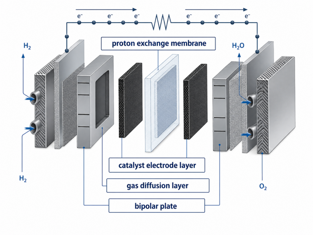
Components of Proton Exchange Membrane Fuel Cells
In the above diagram, besides the basic chemical reaction principles of fuel cells, important components are also involved: the membrane electrode assembly (MEA) and bipolar plate. The MEA includes the proton exchange membrane, gas diffusion layer, and catalyst electrode layer. There are two common MEA fabrication techniques: one is to evenly spray the catalyst onto the gas diffusion layer, known as a gas diffusion electrode (GDE); the other is to evenly spray the catalyst onto the proton exchange membrane, known as a catalyst coated membrane (CCM). Using the CCM technique can reduce the amount of precious metal used.
With this brief introduction, you now have a basic concept of proton exchange membrane fuel cells. Next, we will introduce each of these components in detail.
1. Membrane Electrode Assembly(MEA)
The membrane electrode assembly, or MEA, is the core electrochemical unit of a PEM fuel cell. It integrates the proton exchange membrane, catalyst layers and gas diffusion layers into one working structure. The U.S. Department of Energy describes the MEA as the heart of a PEM fuel cell and identifies the membrane, catalyst layers, gas diffusion layers, gaskets, and bipolar plates as key parts of the cell.In a complete PEM fuel cell stack, many MEAs are compressed between bipolar plates to create the required voltage and power output. MEA quality therefore has a direct effect on voltage, durability, power density and efficiency.
Proton exchange membrane
As a key component of proton exchange membrane fuel cells (PEMFC), the main functions of the proton exchange membrane include: separating the fuel and oxidant, supporting the electrocatalyst, and ensuring the smooth progress of the reaction; selectively conducting protons while blocking the transmission of electrons. The performance of the proton exchange membrane significantly impacts the performance, lifespan, and cost of PEMFCs. Based on the usage conditions of PEMFCs, an excellent electrolyte membrane material should have high proton conductivity, good chemical stability, good thermal stability, good mechanical properties, low gas permeability, low water electro-osmotic drag coefficient, low cost, and be easy to form and process.
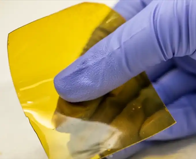
Proton exchange membranes can be divided into three main types:
- Perfluorosulfonic acid membranes: Nafion is the most widely used example. It offers strong chemical stability, good mechanical strength, and high proton conductivity under humid conditions. However, it is expensive, difficult to manufacture, and highly dependent on water management.
- Partially fluorinated and hydrocarbon membranes: These membranes are studied as lower-cost alternatives to perfluorosulfonic acid membranes. They are easier to process and can offer good water uptake, but they still need a better balance between proton conductivity, mechanical strength, and long-term durability.
- Composite membranes: These membranes combine polymer materials with porous supports or functional fillers. They can improve dimensional stability, water retention, mechanical strength, or gas barrier performance. However, some fillers may reduce overall proton conductivity, so material selection is important.
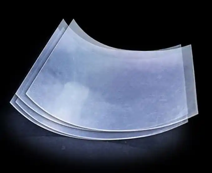
Catalyst Layer
The catalyst electrode layer is typically prepared from an electrocatalyst and a proton exchange resin solution. It is a thin, porous structure with electrochemical activity for hydrogen oxidation or oxygen reduction. The thickness of the catalyst electrode layer is generally between 5 and 10μm. The electrocatalyst is one of the key materials in fuel cells. Its function is to reduce the activation energy of the reaction, promote the redox process of hydrogen and oxygen at the electrodes, and increase the reaction rate.
Platinum Loading in the Catalyst Electrode Layer
Platinum is mainly used in the catalyst electrode layer to support two key reactions:
- Hydrogen oxidation reaction (HOR) at the anode
- Oxygen reduction reaction (ORR) at the cathode
The anode reaction is relatively fast and has a very low overpotential. Because of this, the anode can work with very low platinum loading, such as about 0.05 mg/cm², without major energy loss.
The cathode reaction is much more difficult. The oxygen reduction reaction has slow kinetics, low exchange current density, and several intermediate reaction steps. As a result, the cathode ORR becomes the rate-limiting step of the whole fuel cell reaction.
Why the Cathode Catalyst Layer Is Critical
The cathode catalyst layer has a major impact on PEMFC efficiency. In low-temperature fuel cells, the oxygen reduction reaction can account for a large share of total efficiency loss. This is why improving cathode catalyst activity is one of the key research directions for fuel cell commercialization.
A good cathode catalyst needs to provide:
- High oxygen reduction activity
- Good stability under acidic conditions
- Low platinum loading
- Strong resistance to degradation during vehicle operation
- Acceptable cost for large-scale production
Current Commercial Pt/C Catalysts
The most common cathode electrocatalyst in PEMFCs is commercial Pt/C catalyst. It usually consists of platinum nanoparticles supported on carbon. These platinum nanoparticles are often around 3–5 nm in size.
For example, commercial 40 wt% Pt/C catalysts have been widely used as benchmark materials. However, their mass activity and specific activity are still lower than the performance targets set for future fuel cell commercialization. This means that current commercial catalysts still need improvement in both activity and platinum utilization.
Why Platinum Usage Must Be Reduced
The high cost and limited supply of platinum remain major barriers to large-scale PEMFC commercialization. Fuel cell vehicles can require a significant amount of platinum, and this increases the total system cost.
Although platinum usage has already decreased compared with earlier PEMFC systems, further reduction is still needed. The long-term goal is to achieve much lower platinum loading while maintaining power output, efficiency, and durability.
Catalyst Durability Challenges
Platinum catalysts also face durability problems during real vehicle operation. Under dynamic operating conditions, platinum nanoparticles may:
- Agglomerate into larger particles
- Migrate across the catalyst layer
- Dissolve and redeposit
- Lose active surface area over time
In addition, high potentials caused by open circuit, idling, and start-stop conditions can accelerate carbon support corrosion. Once the carbon support corrodes, catalyst particles may detach or become less effective. This reduces fuel cell performance and shortens service life.
Main Strategies for Reducing Platinum Usage
Researchers are working on several methods to reduce platinum loading while improving catalyst activity and stability:
- Pt alloy catalysts: Transition metals are added to platinum to improve catalytic activity and reduce platinum content.
- Crystal structure regulation: The atomic structure of the catalyst is adjusted to expose more active sites.
- Core-shell catalysts: A thin platinum shell is placed over a lower-cost core material to improve platinum utilization.
- Non-precious metal catalysts: Researchers are also developing catalysts based on cheaper metals, although their activity and durability still need further improvement.
Overall, the catalyst layer remains a key technical challenge in PEMFC development. Future progress depends on reducing platinum usage, improving cathode ORR activity, and increasing long-term catalyst stability under real operating conditions.
Gas Diffusion Layer
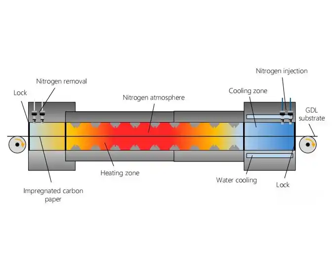
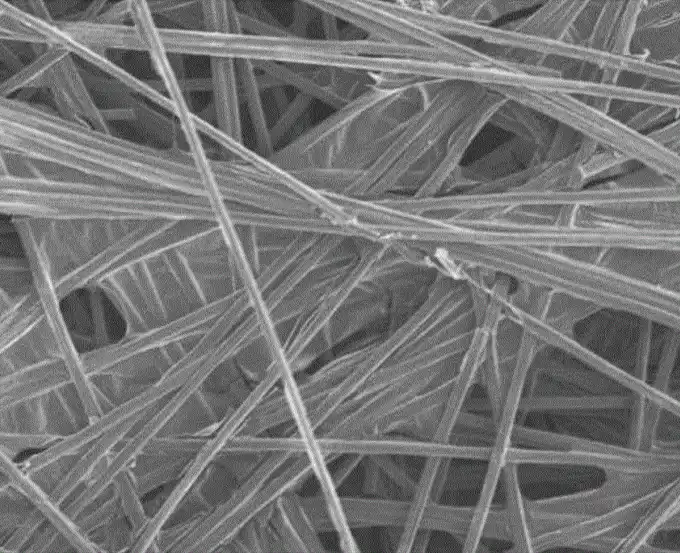
The gas diffusion layer (GDL) is located between the flow field and the catalyst layer. Its main functions are to provide transport channels for the reacting gases and the produced water and to support the catalyst. Therefore, the performance of the GDL substrate material directly affects the performance of the fuel cell. A high-performance GDL must have good mechanical strength, appropriate pore structure, good electrical conductivity, and high stability.
Composition of the Gas Diffusion Layer
The gas diffusion layer is usually composed of a porous carbon fiber substrate and a microporous layer. The porous carbon fiber substrate is often hydrophobically treated porous carbon paper or carbon cloth, with a thickness of 200-400 μm. The microporous layer, also called the water management layer (approximately 100 μm), typically consists of conductive carbon black and a binder. Its function is to reduce the contact resistance between the catalyst layer and the support layer, ensure uniform redistribution of the reactant gases and product water between the flow field and the catalyst layer, enhance conductivity, and improve electrode performance.
Function of the Gas Diffusion Layer (GDL)
The GDL distributes the reactant gases over the electrode and conducts electrons and heat between the electrode and the bipolar plate. More importantly, the GDL plays a critical role in the water management of the fuel cell. This is because the proton exchange membrane in the membrane electrode assembly needs to conduct protons under humid conditions, while excess water can cause flooding of the electrodes. Thus, the GDL must balance the appropriate amount of water present on the electrode surface.
High-Performance Gas Diffusion Layer
A high-performance GDL can directly improve the working performance of the fuel cell. What constitutes high performance? It must meet the following requirements:
Corrosion resistance: The GDL is in direct contact with the catalyst layer and is subject to high electrochemical corrosion during reactions.
Porosity and breathability: The GDL must be a porous, breathable material, as it mediates the diffusion of hydrogen/oxygen or methanol/air to the catalyst layer.
High electrical conductivity: Since the GDL conducts electrons, it must have high electrical conductivity.
High thermal conductivity: Electrochemical reactions are exothermic, and excessive heat can damage the proton exchange membrane. The GDL must be able to conduct heat away to prevent damage to the proton exchange membrane.
High hydrophobicity: Water produced during fuel cell reactions can degrade performance. Therefore, the GDL must be able to expel water effectively.
Bipolar Plate
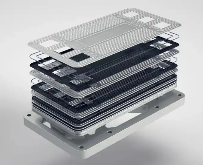
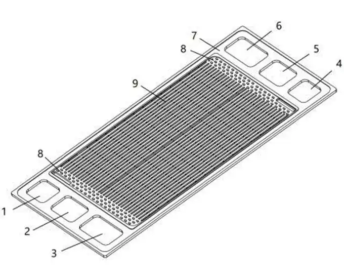
The fuel cell bipolar plate is a crucial component of a proton exchange membrane fuel cell. It features channels on both sides: one side contacts the anode of one cell to provide the anode flow field, and the other side contacts the cathode of another cell to provide the cathode flow field. Typically, the water channels are isolated from the anode and cathode flow channels within the bipolar plate. The bipolar plate serves functions such as collecting and conducting current, separating gases, supporting the cell stack, and connecting individual cells in series.
Structure of the Bipolar Plate
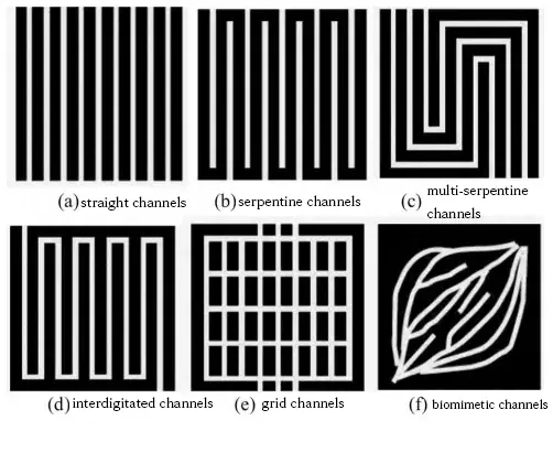
The bipolar plate accounts for 70%-80% of the cell’s mass, and the cost of machining graphite flow field plates constitutes 60%-70% of the total cell stack processing cost. The structure and size of the flow channels significantly affect cell performance. Therefore, the design and structure of the bipolar plate have a substantial impact on the cell stack. Current research on bipolar plates mainly focuses on material selection to meet the technical requirements for fuel cell commercialization.
Note: Impact of bipolar plate flow channels on fuel cell performance
Types of Bipolar Plates
Bipolar plates must provide electrical conductivity, mechanical strength, low hydrogen permeability, corrosion resistance, dimensional stability, low weight, and good manufacturability.
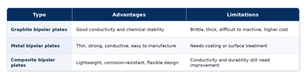
Based on material, bipolar plates are mainly divided into three types:
- Graphite bipolar plates
- Metal bipolar plates
- Composite bipolar plates
Graphite Bipolar Plates
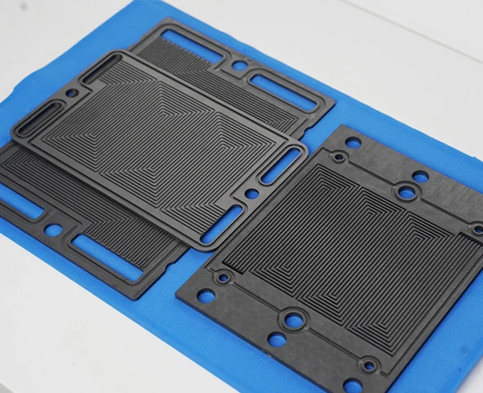
Graphite bipolar plates were used early in fuel cell development. They offer good electrical conductivity, low density, and strong chemical stability.
Their main limitations are brittleness, difficult machining, and poor dimensional control during processing. To meet strength requirements, graphite plates often need to be thicker, which increases stack size, weight, and processing cost.
Note: Understanding Graphite Bipolar Plates: The Key Component of Fuel Cells
Metal Bipolar Plates
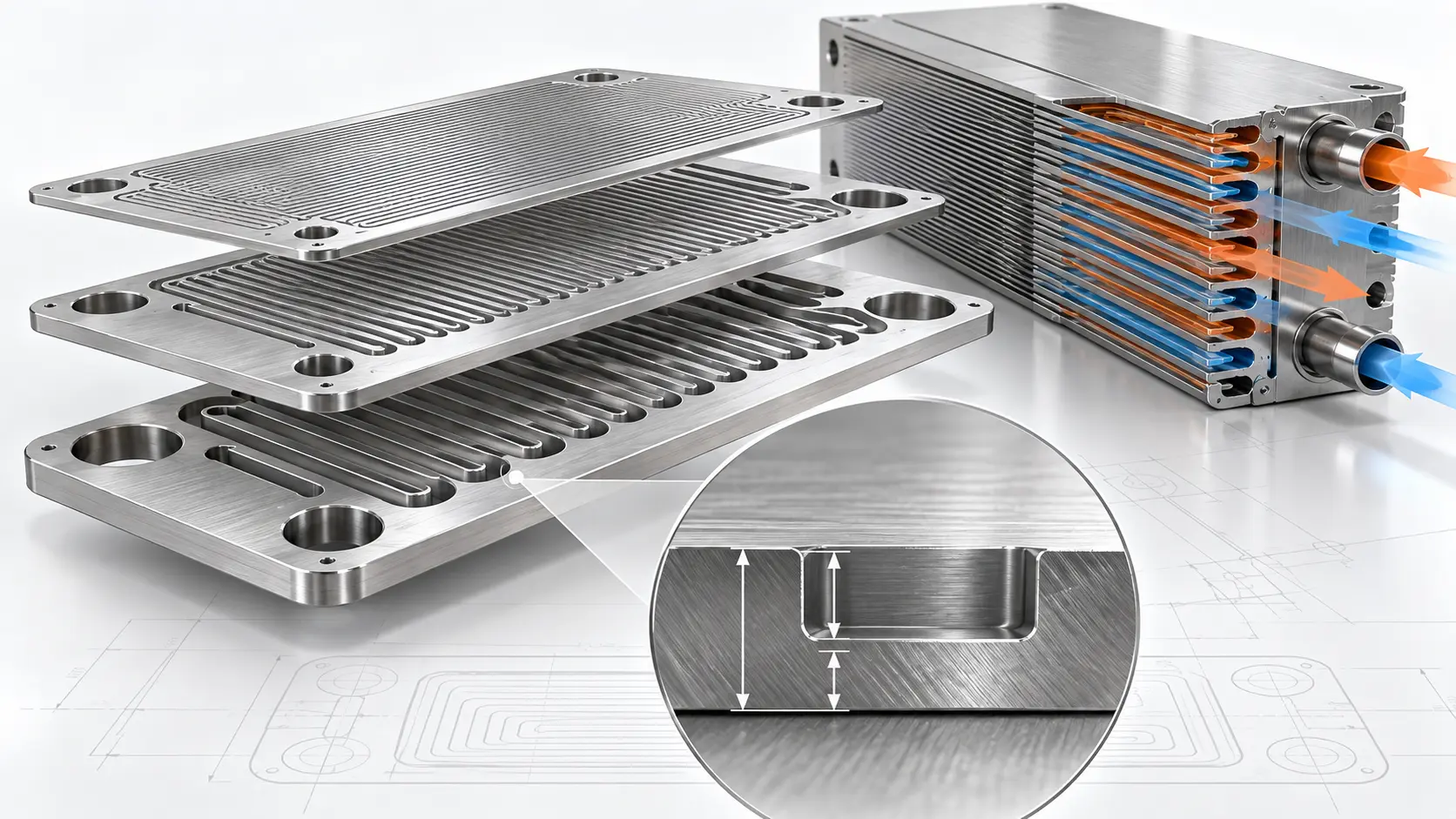
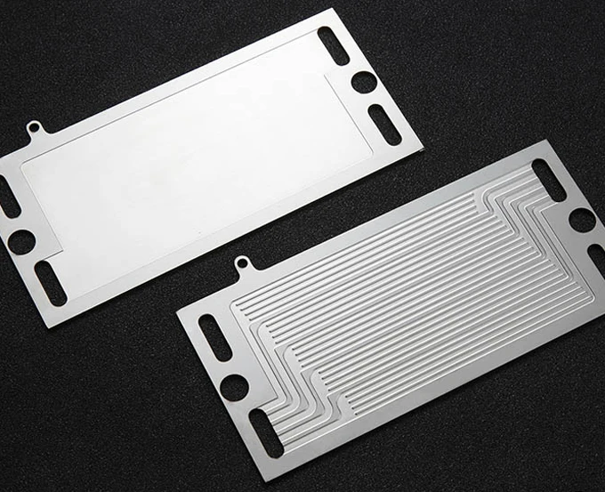
Metal bipolar plates offer high strength, good toughness, electrical conductivity, and thermal conductivity. They can also be made thinner than graphite plates, which can improve stack power density. Engineers selecting a channel-forming method can compare photochemical etching, stamping, hydroforming, and CNC machining.
Metal bipolar plates are often designed below 1 mm, although final feasibility depends on the material, plate geometry, channel depth, tolerance, and manufacturing method. For stainless steel projects, this 304 vs 316L bipolar plate material guide explains the differences in corrosion resistance, cost, coating needs, and manufacturing suitability.
The main challenge is corrosion in the acidic and humid PEMFC environment. Coating or surface treatment may therefore be required to control corrosion and interfacial contact resistance. Buyers should also understand how etching quality affects bipolar plate coating performance, including the effects of surface cleanliness, channel accuracy, and edge condition.
TMNetch reviews thin-metal bipolar plate projects according to the material, plate thickness, channel geometry, channel depth, coating, and tolerance requirements. See its custom bipolar plate manufacturing capabilities.
Composite Bipolar Plates
Composite bipolar plates combine conductive materials, polymer frames, thin metal sheets, or other reinforced structures. They aim to balance conductivity, strength, corrosion resistance, weight, and cost.
They can reduce stack weight and improve design flexibility. However, their electrical conductivity, mechanical strength, and long-term durability still need further improvement for demanding PEMFC applications.
Air Compressor
The air compressor is a crucial component of the cathode air supply system in automotive fuel cells. By pressurizing the air entering the stack, it can increase the power density and efficiency of the fuel cell, and reduce the size of the fuel cell system. However, the parasitic power consumption of the air compressor is quite high, accounting for about 80% of the auxiliary power consumption of the fuel cell. Its performance directly affects the efficiency, compactness, and water balance characteristics of the fuel cell system. Therefore, fuel cell projects around the world place great emphasis on the research of air compressors.
Unlike conventional secondary batteries, fuel cell power generation requires a complex set of auxiliary systems for material supply, temperature control, and more. A typical fuel cell power generation system includes air subsystems, hydrogen subsystems, thermal management subsystems, and electronic control subsystems. Key components include air compressors, humidifiers, hydrogen recirculation pumps, and more.
If you are selecting parts for a complete stack, this fuel cell stack component selection guide explains how bipolar plates, MEAs, GDLs, seals, and current collectors work together.
PEM Fuel Cell Efficiency & Performance Data
PEM fuel cell efficiency depends on the measurement boundary. A single cell or stack may show higher efficiency than a complete fuel cell system. A full system also includes compressors, humidifiers, cooling loops, hydrogen recirculation, and control electronics. Therefore, efficiency data should clearly state whether it refers to the cell, stack, or system level.
Key performance points include:
- Practical efficiency: PEMFC system efficiency is often discussed in the range of about 40–60%. Under favorable stack-level conditions, some values may approach 60–70%, but these figures should be verified with reliable sources before publication.
- Efficiency losses: Actual efficiency is reduced by three main losses. Activation loss comes mainly from slow cathode oxygen reduction. Ohmic loss comes from resistance in the membrane, electrodes, bipolar plates, and interfaces. Mass transport loss happens when gas supply, water removal, or diffusion cannot keep up with current demand.
- Power density: PEMFC power density is important for automotive and compact systems. Automotive stacks may report broad volumetric power density values, such as around 2–6 kW/L, depending on stack design, active area, operating pressure, and cooling system. Current OEM data should be checked before using this range.
- High-temperature PEMFC: HT-PEMFC operates at higher temperatures than conventional PEMFC systems, often around 80–200°C depending on membrane chemistry. Higher temperature can improve CO tolerance, simplify water management, and provide more useful waste heat. However, it also brings new challenges in materials, durability, and start-up behavior.
If your PEMFC project requires custom etched metal bipolar plates, TMNetch can review the base material, flow-field pattern, channel depth, coating requirements, tolerance target, and prototype plan before production.
FAQs
What is the difference between PEMFC and SOFC?
PEMFC stands for proton exchange membrane fuel cell. It uses a polymer membrane and usually operates at low temperatures, often around 50–100°C. SOFC stands for solid oxide fuel cell. It uses a ceramic electrolyte and operates at much higher temperatures, often several hundred degrees Celsius. PEMFCs are better suited for vehicles and compact power systems. SOFCs are often used in stationary power and high-temperature applications.
How long do PEM fuel cells last?
PEM fuel cell lifetime depends on application, load profile, start-stop cycles, humidity, temperature, fuel purity and component quality. Automotive, stationary and portable systems have different durability requirements. Common degradation factors include catalyst loss, membrane thinning, carbon corrosion, bipolar plate corrosion and seal aging. For procurement, lifetime claims should be checked through test standards, voltage decay data and real operating profiles rather than headline hours alone.
What are the main challenges facing PEMFC commercialization?
The main challenges include hydrogen infrastructure, platinum catalyst cost, membrane durability, water management, bipolar plate cost and system-level reliability. Fuel purity is also important because contaminants such as carbon monoxide can poison the catalyst. For large-scale commercialization, suppliers must reduce cost while improving durability. This requires progress in materials, manufacturing, coating, stack assembly and quality control.
How do bipolar plates affect PEM fuel cell performance?
Bipolar plates affect gas distribution, current collection, heat removal, water management, sealing and stack compactness. Poor flow field design can cause uneven reactant distribution or water flooding. High contact resistance reduces electrical efficiency. Corrosion can contaminate the MEA and reduce stack life. Thin metal bipolar plates can improve power density, but they require accurate flow fields and reliable coatings. See“bipolar plate manufacturing process” for a deeper manufacturing guide.
Conclusion
This concludes the entire content of this article, which mainly revolves around the principles of proton exchange membrane fuel cells and the construction of various components. It explains the working principle formula of PEMFC and highlights the crucial roles of the five main components in PEMFC: platinum catalyst, proton exchange membrane, gas diffusion layer, catalyst electrode layer, and bipolar plate. Each component significantly affects the performance, lifespan, and cost of PEMFC.
For PEMFC projects moving from stack design to component sourcing, engineers can review TMNetch’s custom metal bipolar plates for flow-field geometry, material, thickness, coating, tolerance, prototype, and production requirements.
Related articles:
What are the main differences between PEM fuel cell,FCAFC,MCFC,SOFC and DMFC ?
Practical Applications of Proton Exchange Membrane Fuel Cells