
Choosing the right copper etching services starts with the part’s function. Buyers should compare the copper grade, material thickness, feature geometry, tolerance, surface finish, order volume, and inspection requirements before selecting a manufacturing route.
The lowest quotation is not always the best option. A supplier must understand how each design decision affects conductivity, strength, dimensional accuracy, assembly, and long-term production stability.
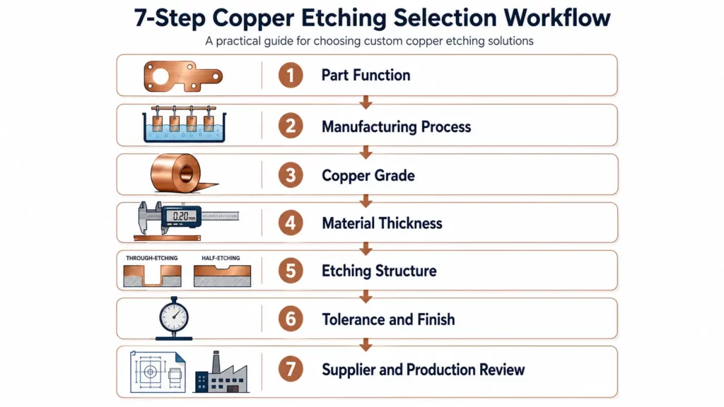
Quick Answer: How Do You Choose a Copper Etching Services?
Follow these seven steps:
- Define the part’s electrical, thermal, mechanical, and environmental requirements.
- Confirm that chemical etching suits the thickness and geometry.
- Select a copper grade based on conductivity, strength, formability, and corrosion resistance.
- Match material thickness to holes, slots, webs, and other fine features.
- Define critical tolerances and inspection methods.
- Select plating, coating, polishing, bending, or other secondary processes.
- Compare the supplier’s design support, process control, capacity, and production consistency.
The right choice should support both the current prototype and future production requirements.
Start With the Part’s Function
Starting by defining what the copper part must do inside the final product, instead of starting by comparing supplier prices.
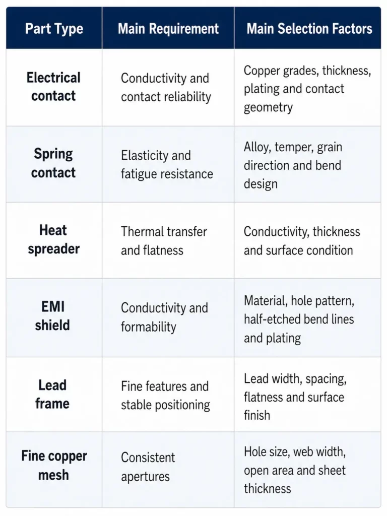
An electrical contact may need high conductivity and a stable contact surface. A spring contact needs strength, elasticity, and resistance to stress relaxation. A heat spreader or an etched vapor chamber component requires suitable thermal conductivity, controlled thickness, and consistent flatness. An EMI/RFI shielding component may need conductivity, half-etched bend lines, ventilation openings, reliable contact areas, and surface protection.
Before requesting a quotation, define the part’s functional, environmental, assembly, and production requirements.
These details help the supplier review the drawing as a functional component rather than only as a flat metal shape.
Step 1: Confirm That Chemical Etching Is the Right Process
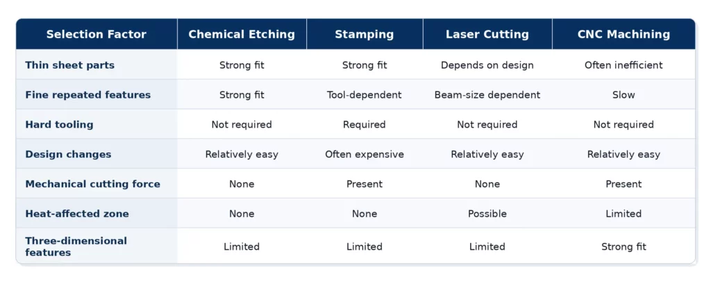
Copper chemical etching removes selected areas from a sheet through a controlled chemical reaction. The process does not use a cutting tool, stamping force, or concentrated laser heat.
This makes it useful for thin, flat copper parts with complex outlines, repeated holes, narrow slots, or detailed patterns. TMNetch states that its copper etching process produces components without mechanical stress, heat-affected zones, or conventional cutting burrs.
Copper Etching Is Often Suitable When
Consider copper photo etching when the part:
- Is made from thin copper or copper-alloy sheet
- Contains many small holes or slots
- Has a complex two-dimensional outline
- Requires smooth, burr-free edges
- Must remain flat and free from cutting stress
- May require design changes during development
- Includes repeated patterns across one sheet
- Requires through-etched and half-etched features
- Must be produced without expensive hard tooling
Because the pattern is transferred through photographic tooling, engineers can normally change a design without rebuilding a hard stamping die.
Consider Stamping When
Stamping may be more economical for stable designs at very high volumes, while laser cutting or CNC machining may be more suitable for thicker materials, simple profiles, or three-dimensional features.
Step 2: Choose the Right Copper or Copper Alloy
Material selection affects conductivity, strength, formability, corrosion resistance, surface treatment, and final cost.
Do not write only “copper” on the RFQ. State the exact alloy and temper whenever possible.
Choose C11000 When Conductivity Is the Priority
C11000 is an electrolytic tough pitch copper. According to the Copper Development Association’s C11000 alloy profile, it is a high-conductivity copper with a minimum conductivity of 100% IACS in the annealed condition. Its listed applications include busbars, electrical conductors, and contacts.
C11000 may be considered for:
- Electrical contacts
- Conductive plates
- Busbar layers
- Battery connection parts
- Heat spreaders
- Thermal transfer components
However, conductivity is not the only requirement. Buyers should also confirm the temper, mechanical strength, bending operation, surface finish, and joining method.
A soft temper may support forming, while a harder temper may improve rigidity. The correct condition depends on the final assembly.
Choose C26000 Brass When Formability Matters
C26000 is a copper-zinc alloy commonly called cartridge brass. The Copper Development Association’s C26000 alloy profile lists excellent cold-working capacity and typical uses that include electrical connectors and automotive electrical contacts.
C26000 may suit:
- Formed connectors
- Contact plates
- Shielding components
- Decorative industrial parts
- Components that require later bending
Its conductivity is lower than that of high-purity copper. Therefore, it should not automatically replace C11000 in parts where electrical or thermal performance is the main requirement.
Choose Phosphor Bronze for Spring Contacts
Phosphor bronze provides a different balance of strength, formability, and conductivity. Copper.org notes that phosphor bronze can provide higher contact force than cartridge brass and is available in several tempers.
C51000 is used in electrical connectors, flexing contact blades, spring components, fuse clips, and precision electronic parts. It also offers excellent cold-working capacity.
Consider phosphor bronze for:
- Spring contacts
- Connector clips
- Fuse clips
- Battery contacts
- Conductive springs
- Switch parts
- Flexible contact blades
For these parts, the material temper may be as important as the alloy number. The drawing should define the required hardness, spring force, bend direction, and performance after forming.
Consider Beryllium Copper for High-Strength Spring Contacts
Beryllium copper is suitable for spring contacts that require high strength, good elasticity, fatigue resistance, and stable contact force. The Copper Development Association’s C17200 alloy profile lists connectors, relay parts, spring connectors, switch parts, and springs among its typical applications.
When machining or finishing this alloy, suppliers should follow OSHA’s beryllium exposure-control guidance by controlling airborne dust through measures such as local exhaust ventilation, wet processing, and suitable protective measures.
Choose Copper-Nickel for Corrosive Environments
Copper-nickel alloys may be suitable when corrosion resistance matters more than maximum conductivity.
C70600 is a 90/10 copper-nickel alloy. The Copper Development Association lists applications exposed to fresh water, salt water, and petrochemical environments.
Possible applications include:
- Marine equipment
- Corrosion-resistant plates
- Industrial screens
- Condenser-related components
- Parts exposed to salt water
The supplier should confirm that the selected copper-nickel grade, thickness, and surface condition are suitable for the required etching chemistry.
Copper Material Selection Table
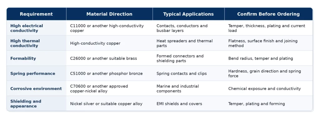
These are material directions, not final engineering approvals. The supplier should review the actual drawing and operating conditions.
Step 3: Match Material Thickness to Feature Geometry
Material thickness affects etching time, side etching, edge profile, minimum feature size, flatness, and dimensional tolerance.
TMNetch lists a copper and copper-alloy thickness range of 0.05 mm to 2.5 mm. It also lists a maximum processing size of 1500 mm × 600 mm. These values describe the general equipment range, not the guaranteed capability of every design.
A 2.5 mm plate cannot normally carry the same fine geometry as a 0.05 mm foil. As thickness increases, the supplier must remove material through a deeper section. This can make very small holes, narrow slots, and thin webs more difficult to control.
Features That Need Early DFM Review
Ask the supplier to review:
- Minimum holes and slots
- Minimum webs and feature spacing
- Edge-to-hole distance
- Internal and external corners
- Long features and large open areas
- Flatness, datums, tabs, and overall dimensions
Attention on not applying one generic minimum-feature rule to every copper project. Results depend on the alloy, temper, thickness, feature position, etch depth, and inspection method.
Ask About Etch Compensation
During chemical etching, material is removed downward and sideways. The sideways removal is often called undercut.
An experienced supplier adjusts the phototool to compensate for this behavior. The correct compensation depends on the material and design.
Before approving a quotation, confirm whether the supplier has reviewed:
- Hole-size compensation
- Slot-width compensation
- External profile compensation
- Closely spaced features
- Sharp corners
- Half-etched regions
- Plating allowance
This review reduces the risk of receiving a part that looks correct on the CAD file but fails during assembly.
Step 4: Select the Etching Structure
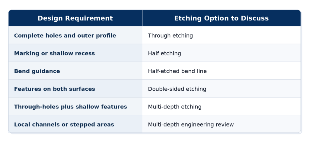
Copper etching can produce more than complete through-holes and external profiles. It can also create fine, repeated patterns for components such as custom lead frames, contacts, screens, and connector structures.
TMNetch lists single-sided, double-sided, and multi-depth copper etching capabilities.
Through Etching
Through etching removes material through the complete sheet thickness.
It can produce:
- Outer profiles
- Holes
- Slots
- Mesh openings
- Connector patterns
- Lead-frame outlines
- Separate flat components
Half Etching
Half etching removes only part of the material thickness.
It may be used for:
- Part numbers
- Logos
- Identification marks
- Recessed areas
- Alignment marks
- Bend lines
- Local thickness reduction
Half-etched bend lines can support later forming. However, the remaining thickness must still provide enough strength for handling and final use.
Double-Sided Etching
Double-sided processing can create aligned features from both surfaces. It can also help form more complex profiles and controlled-depth areas.
Alignment requirements should be stated on the drawing when features on the two sides must match.
Multi-Depth Etching
Multi-depth etching can combine through-holes, recessed areas, markings, channels, and local thickness changes in one component.
These designs require a more detailed feasibility review. The buyer should clearly mark each target depth and state which dimensions are critical.
Step 5: Define Realistic Tolerances and Inspection Methods
Do not place the tightest possible tolerance on every dimension.
A drawing should separate critical dimensions from non-critical dimensions. This helps the supplier focus process control and inspection resources where they create real value.
Classify the Dimensions
Use four groups:
- Critical-to-function dimensions
- Assembly dimensions
- General manufacturing dimensions
- Reference dimensions
A connector contact area may require tighter control than a non-functional outer edge. A locating hole may require a different inspection method than a decorative marking.
Factors That Affect Tolerance
Copper etching tolerance depends on:
- Alloy
- Temper
- Material thickness
- Part size
- Hole diameter
- Slot width
- Feature spacing
- Etch depth
- Flatness
- Surface treatment
- Measurement method
TMNetch states that suitable copper designs can achieve tolerances as tight as ±0.03 mm. This should not be interpreted as a standard tolerance for every dimension or every thickness.
Request a drawing review before placing this value across the entire part.
Define the Inspection Plan
Ask the supplier:
- Which dimensions will receive full inspection?
- Which dimensions will use sampling?
- Will the supplier provide a first article inspection report?
- Can it provide material certificates?
- How will it inspect small holes and slots?
- How will it measure flatness?
- Will it inspect the part before or after plating?
- How will it control repeat orders?
- Which drawing revision will control production?
TMNetch states that its copper parts are inspected with 2D vision equipment and documented through FAI and outgoing quality control reports.
The RFQ should still specify the exact report and sampling level required by the project.
Step 6: Select Surface Finishing and Secondary Processes
Copper can oxidize during storage and use. It may also require a functional finish for soldering, electrical contact, corrosion protection, appearance, or assembly.
TMNetch supports one-stop chemical etching services that can combine copper etching with plating, forming, polishing, cleaning, inspection, and other required surface treatments.
Select the Finish by Function
A surface finish may be required to:
- Improve solderability
- Improve contact performance
- Increase corrosion resistance
- Reduce oxidation
- Improve wear resistance
- Support wire bonding
- Prepare the part for assembly
- Improve appearance
Do not select a coating based only on common industry practice. Confirm the operating environment and downstream assembly process.
State Whether Dimensions Apply Before or After Finishing
Plating adds material to the surface. A coating can reduce the open width of a hole or slot.
The drawing or purchase specification should state whether the required dimensions apply to:
- The etched blank
- The part after plating
- The part after forming
- The fully finished component
This point is important for small holes, contact areas, narrow slots, and press-fit features.
Coordinate Bending With Etching
A copper shield or connector may require both etching and bending.
The supplier should review:
- Bend position
- Bend radius
- Grain direction
- Material temper
- Half-etched bend lines
- Springback
- Plating sequence
- Final dimensional inspection
When possible, quote the etched and formed component as one controlled project. This reduces the risk of tolerance conflict between two suppliers.
Step 7: Match the Supplier to Prototype and Production Needs
Prototype requirements differ from volume-production requirements.
| Project Stage | Main Priorities |
|---|---|
| Prototype | DFM feedback, low tooling risk, revision flexibility, sample inspection |
| Volume production | Material stability, traceability, capacity, inspection consistency, delivery control |
Compare Total Project Cost
The unit price is only one part of the purchasing decision.
Compare:
- Material cost
- Phototool cost
- Sampling cost
- Inspection cost
- Plating or coating cost
- Forming cost
- Packaging
- Shipping
- Design-change cost
- Rejection risk
- Future repeat-order cost
A lower quotation may exclude material certification, detailed inspection, surface protection, or suitable packaging. Compare each quotation against the same drawing revision and specification.
Step 8: Evaluate Copper-Specific Supplier Capabilities
A general chemical etching supplier may not have equal experience with every copper alloy. In addition to reviewing copper-specific capabilities, buyers can use this chemical etching supplier checklist to evaluate quality control, inspection, production capacity, documentation, lead time, and secondary services.
Ask copper-specific questions before placing the order.
Material Experience
Confirm whether the supplier has processed:
- The exact copper alloy
- The required temper
- The required thickness
- A similar feature pattern
- The required finish
- A similar final application
Undercut and Edge Control
Ask how the supplier controls:
- Small holes
- Narrow slots
- Thin webs
- Sharp corners
- Closely spaced features
- Large open areas
- Half-etched features
- Tool compensation
Surface and Oxidation Control
Ask how the supplier handles:
- Cleaning after etching
- Fingerprint prevention
- Surface protection
- Storage
- Packaging
- Plating preparation
- Shipment in humid conditions
Prototype-to-Production Control
Confirm:
- Whether prototype settings are recorded
- Whether production uses the same material specification
- How the supplier manages drawing revisions
- How it controls different raw-material lots
- How it approves process changes
- How it handles repeat-order inspection
Copper Etching RFQ Checklist
A complete RFQ helps the supplier provide a more accurate technical review and quotation.
Include:
- CAD drawing and PDF drawing
- Drawing revision
- Copper or copper-alloy grade
- Material temper or hardness
- Sheet thickness
- Overall dimensions
- Critical dimensions
- Dimensional tolerances
- Flatness requirement
- Minimum holes, slots, and webs
- Through-etched and half-etched areas
- Required etching depths
- Surface finish or plating
- Bending or forming requirements
- Inspection plan
- Material certification requirements
- Prototype quantity
- Production quantity
- Estimated annual demand
- Packaging requirements
- Target delivery date
- Final application and operating environment
When the alloy has not been selected, send the functional requirements instead. State the required conductivity, strength, temperature, corrosion exposure, forming operation, joining process, and surface finish.
Why Consider TMNetch for Custom Copper Etching?
TMNetch provides copper chemical etching for electrical, thermal, shielding, semiconductor, and industrial components.
Its published copper capabilities include:
- Copper thicknesses from 0.05 mm to 2.5 mm
- Processing sizes up to 1500 mm × 600 mm
- Single-sided, double-sided, and multi-depth etching
- Tolerances as tight as ±0.03 mm for suitable designs
- Five automated etching lines
- Production capacity up to 4,500 square metres per month
- 2D vision inspection
- FAI and outgoing quality reports
- Plating, coating, polishing, and custom surface treatments
These values describe general manufacturing capability. Final feasibility depends on the copper grade, temper, thickness, geometry, tolerances, finish, and inspection requirements.
Send the drawing for an engineering review together with the material grade, thickness, critical tolerances, surface finish, quantity, and final application.
FAQs
How do I choose the right copper grade for chemical etching?
Start with the functional requirement. Use a high-conductivity copper when electrical or thermal performance is the priority. Consider brass when formability is important, phosphor bronze for spring performance, and copper-nickel alloys for corrosive environments. The supplier should confirm the final alloy and temper against the drawing.
What tolerance can copper etching achieve?
TMNetch states that suitable copper designs can reach tolerances as tight as ±0.03 mm. This value does not apply automatically to every dimension. Material thickness, alloy, feature size, flatness, and inspection method affect the result.
Does every etched copper part need plating?
No. Plating depends on the required solderability, contact resistance, oxidation protection, corrosion resistance, wear resistance, and appearance. The drawing should state whether dimensions apply before or after plating.
Is copper etching suitable for prototypes?
Yes. Copper etching can support prototypes because it does not require a hard stamping die. It is especially useful when the design may change. Buyers should still confirm that prototype materials and process conditions represent future production.
Conclusion
The right copper etching supplier should review the alloy, thickness, feature geometry, tolerance, finish, inspection method, and production volume before production. Submit your drawing for a project-specific feasibility review rather than comparing suppliers by unit price alone.