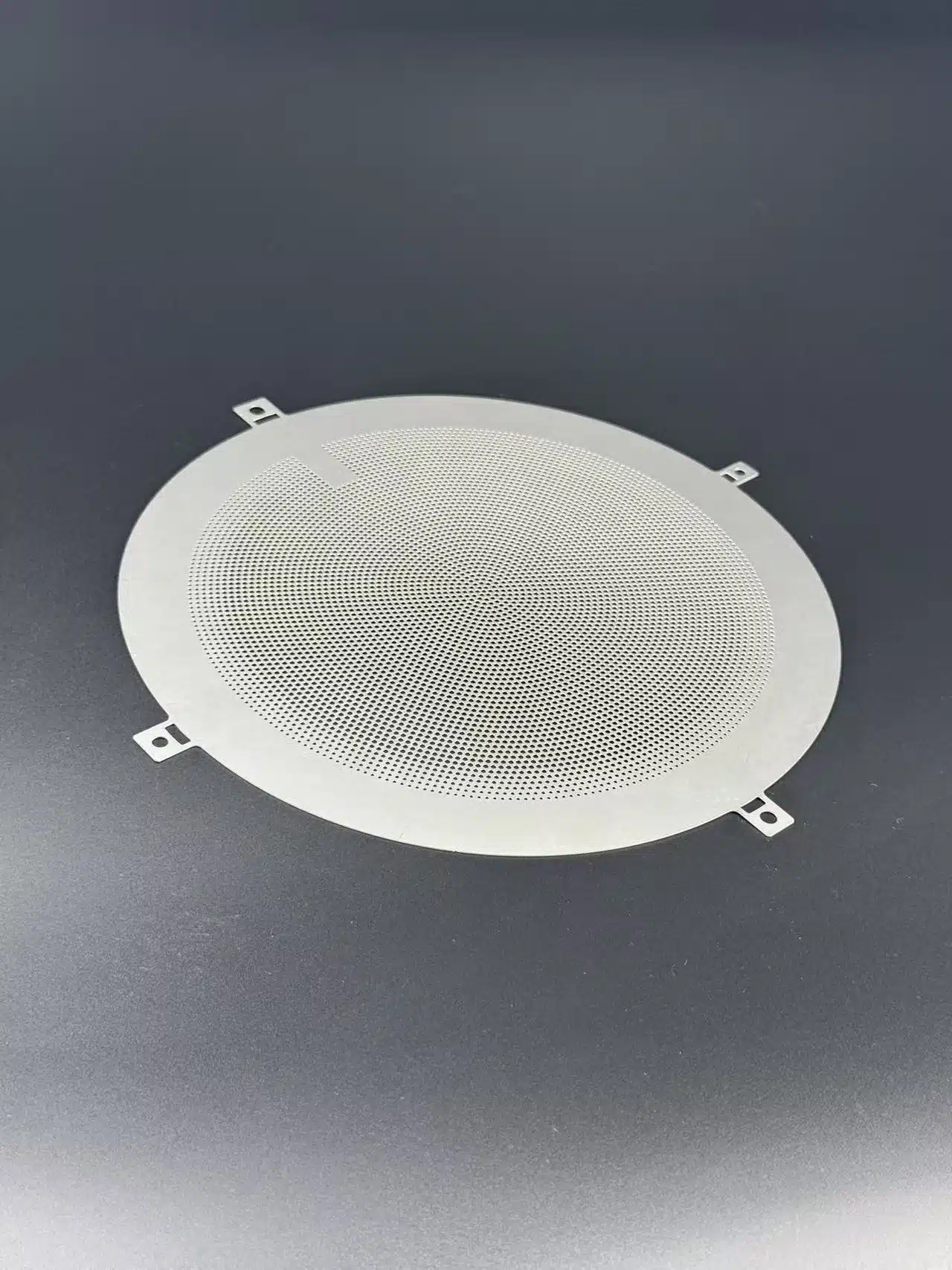

Fuel cell flow field plates commonly use parallel, serpentine, interdigitated and pin-type layouts. Each routes reactant gases differently. Comparing bipolar flow channel design means examining gas supply, liquid-water removal and pressure drop together. Start with candidate layouts for the intended operating conditions. Then develop the channel dimensions and verify the manufactured plate.
This guide focuses on reactant-gas flow fields in proton exchange membrane fuel cells, or PEM fuel cells.
Key Takeaways
- Separate the plate’s flow-path layout from the channel cross-section.
- Compare gas distribution, drainage and pressure drop under relevant operating conditions.
- Take selected layouts through sizing, manufacturing review and validation.
What Is a Flow Field Plate in a PEM Fuel Cell?
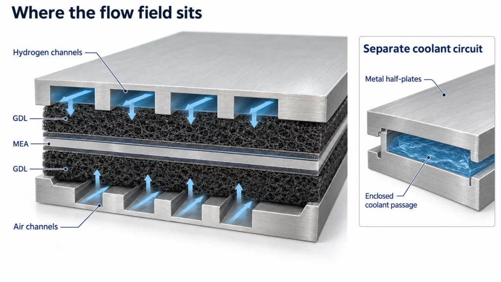
A flow field plate carries gas passages next to the gas diffusion layer, or GDL. These channels supply reactants to the membrane electrode assembly, while the porous GDL supports transport toward the catalyst layer.
Hydrogen and air have separate paths on their respective electrode sides. A bipolar plate may also contain internal coolant passages, which form a different fluid circuit.
Here, “flow field” describes the gas-path arrangement. For the wider electrical and structural roles, see bipolar plate functions.
Compare Four Common Fuel Cell Flow Field Types
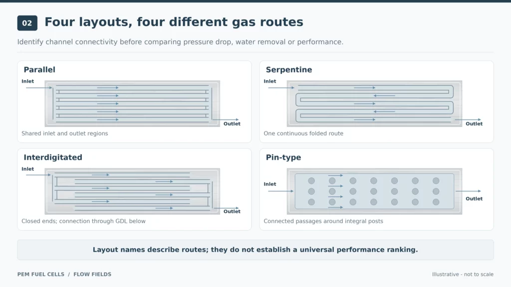
Use the table to identify the gas route and the questions each layout raises. It provides a screening framework for subsequent design work.
| Layout | Main gas route | Pressure-drop and drainage concern | Check next |
|---|---|---|---|
| Parallel | Several channels connect inlet and outlet regions. | Water blockage can redistribute flow between channels. | Manifold distribution and wet-channel behaviour. |
| Serpentine | One or more paths turn repeatedly across the plate. | Longer paths trade drainage capability against flow resistance. | Path length, flow sharing and operating range. |
| Interdigitated | Gas moves between dead-ended channel sets through the GDL. | Porous-layer resistance contributes to the required pressure difference. | GDL properties, compression and water state. |
| Pin-type | Gas passes around an array of posts or islands. | Local routing and water removal depend on the arrangement. | Post spacing, feed arrangement and stagnant regions. |
Parallel Flow Fields
A parallel flow field divides the supply among several channels. “Parallel” describes this connected layout; it does not specify a channel width-to-depth ratio.
Shorter paths can reduce resistance compared with a long serpentine route. The engineering challenge is maintaining useful flow through each branch.
Liquid water can change individual channel flow rates. A partially blocked channel may receive less gas while other channels carry more. Equal-looking channels therefore need wet-state evaluation.
Review channel consistency alongside the ports, manifolds and distribution zones. Treat the channel network and its supply region as one distribution system.
Serpentine Flow Fields: Single and Multiple Paths
A serpentine flow channel follows a continuous route with repeated turns. In a single-path design, the supply follows that route from inlet to outlet.
Longer paths can help remove liquid-water slugs while increasing pressure drop. The resulting pumping demand and inlet-to-outlet changes belong in the comparison.
Multiple serpentine paths divide the supply among several folded routes. They change both the effective path length and the flow-sharing problem.
Review each path’s supply and drainage over the intended operating range. A useful serpentine flow layout must balance water removal with the available pressure budget.
Interdigitated Flow Fields
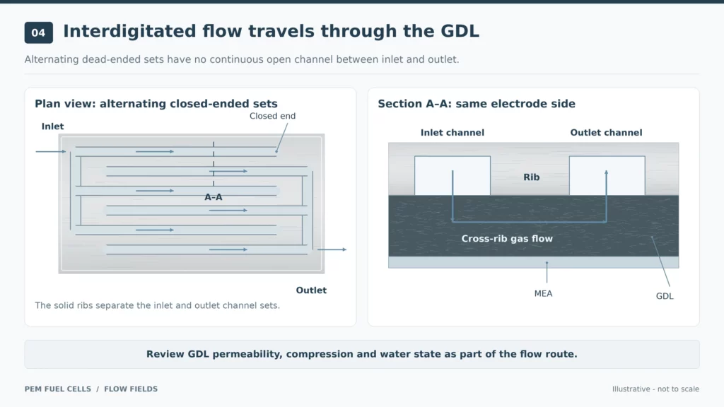
An interdigitated flow field has alternating inlet and outlet channels with closed ends. There is no continuous open channel connecting the two sets.
The pressure difference drives gas through the porous GDL beneath the separating ribs, allowing it to reach an outlet channel. This cross-rib path stays on the same electrode side.
The layout adds pressure-driven transport within the porous layer. That creates a coupled design task: assess reactant transport alongside the pressure needed to maintain it.
Include the GDL’s permeability, compression and water condition in the review. Those properties are part of the flow route.
Pin-Type Flow Fields
Pin-type flow fields contain posts or islands surrounded by connected gas passages. Compared with continuous ribs, the gaps provide additional routes across the patterned area.
Different pin arrangements and supply patterns can produce different operating results. Multiple available paths still require a distribution check.
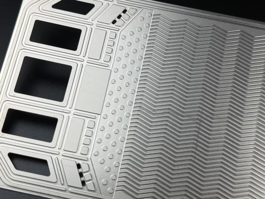
Examine post spacing, local gas supply and persistent water accumulation. For an etched metal flow field, also review how the islands remain connected to the plate base and meet the required geometry.
Biomimetic and Modified Layouts: What Needs Proving?
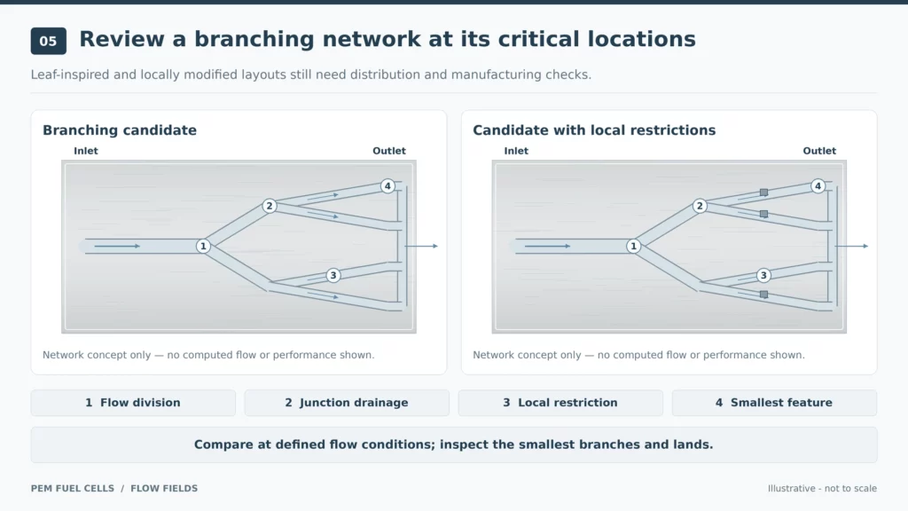
Leaf-inspired layouts use branching networks to spread the gas supply. Modified versions may add local blocks to change transport within those branches.
The balance between electrical output and pressure loss can depend on the supplied airflow. Evaluate the proposed network at the intended flow conditions rather than selecting it from its visual resemblance to a leaf.
For a branching candidate, check:
- How the inlet flow divides between branches.
- Whether junctions or terminal regions retain liquid water.
- How local restrictions affect pressure drop.
- Whether the smallest branches and lands can be manufactured and inspected.
Wavy and spiral paths are further layout variations. Define the problem each variation addresses, then compare it against a suitable baseline. Keep manufacturing methods and numerical analysis separate from the layout classification.
Why Drainage and Pressure Drop Must Be Compared Together
Consider a screening scenario: a candidate has lower dry-gas resistance, but its performance becomes uneven during wet operation. Begin by checking gas distribution and water accumulation.
Overall pressure drop can hide localized channel blockage. A plate-level measurement does not show how every channel is supplied.
Use a combined review:
| Review question | Evidence to examine |
|---|---|
| Does gas reach the required area? | Local flow or current distribution under representative load. |
| Does water persist or block passages? | Wet-state observations and operating stability. |
| Is membrane hydration maintained? | Humidity conditions and corresponding cell response. |
| Is the pressure requirement acceptable? | Pressure drop, flow rate and auxiliary-power demand. |
| Is the comparison consistent? | Load, temperature, humidity, pressure and GDL condition. |
Water management must maintain membrane hydration while removing excess liquid. Maximizing drainage alone leaves part of the problem unresolved.
Likewise, gross electrical power, power density and net system benefit answer different questions. Include the power consumed to drive flow when assessing the overall result.
Once candidates are selected, continue with flow-field optimization and validation.
Channel Layout Is Different from Channel Cross-Section
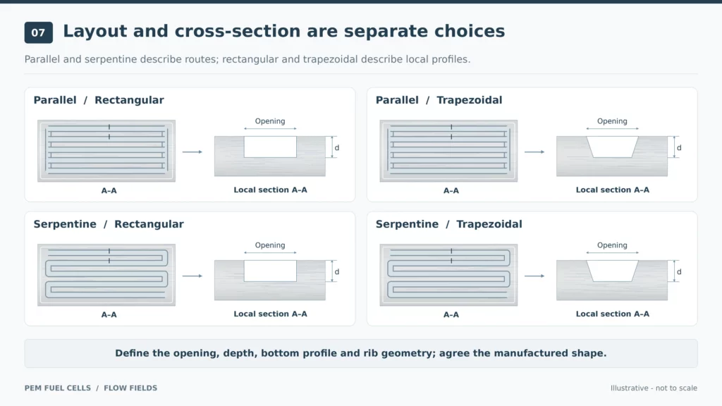
Parallel and serpentine describe routes across the plate. Rectangular and trapezoidal describe a local channel cross-section. A serpentine route can use either section.
Cross-section comparisons can change with reactant humidification conditions. Better water removal under one condition does not establish the best geometry across the operating range.
After selecting a layout, define its opening, depth, bottom profile and rib geometry. Use the separate guide to channel width, depth and rib design for dimensional development.
From a Selected Flow Field to an Etched Metal Plate
Turn the candidate layout into a drawing that a manufacturer can assess. Photochemical machining uses a patterned mask to define metal removal.
Include:
- Material grade, thickness and drawing revision.
- Critical channels, ribs, closed ends, junctions and pin spacing.
- Etch depths, remaining wall and opposing-face alignment.
- Required cross-sections and permitted profile variation.
- Inspection requirements for the critical features.
Undercut and corner rounding affect the produced geometry. Agree on the finished profile during review, including which widths and depths will be inspected.
For the manufacturing details, see etching complex bipolar plate flow channels.
TMNetch Case: A Hybrid Flow-Plate Route
A previous TMNetch patterned flow-plate project combined chemical etching with laser cutting. The recorded material families included 316 stainless steel and titanium.
The practical lesson is to review fine flow features together with large profiles and openings. A combined route can be considered when the drawing contains different manufacturing demands.
This case documents flow-plate fabrication. For a PEM fuel-cell application, gas distribution, drainage and pressure-drop performance still need application-specific validation. Submit the full functional drawing so the manufacturing review covers the interactions between features.
FAQs About Fuel Cell Flow Field Designs
Which flow field type is best for a PEM fuel cell?
Select candidates by gas distribution, water management, pressure drop and the intended operating range. Compare them under consistent conditions.
Is the lowest pressure drop always the best choice?
No. Check that the layout also supplies the active area and manages water. Include auxiliary-power demand in the overall comparison.
Can every flow field concept be made by photochemical etching?
Feasibility requires review of material, thickness, local geometry, depth, remaining wall and inspection requirements.
Select candidate layouts before detailed sizing, manufacturing review and validation. For a metal bipolar plate project, share your patterns, material, thickness, channel drawing and inspection requirements with TMNetch. Request an etching manufacturability review and define the critical features and required delivery condition before sample production.