
Bipolar plate structure determines where fluids enter, how they reach the active area and where they leave. In a proton exchange membrane fuel cell, or PEMFC, the plate also works with gaskets and the membrane electrode assembly to separate neighboring cells and support their operation.
This guide uses a liquid-cooled metal plate with internal manifolds as its reference design. It focuses on ports, distribution zones, sealing boundaries and coolant passages.
For fuel cell plates, the review should include both the individual face and the assembled fluid connections.
Read each feature in two ways: what it connects to, and what it must remain separated from.
How Is a Bipolar Plate Divided into Functional Regions?
Ports, Distribution Zones and the Active-Area Flow Field
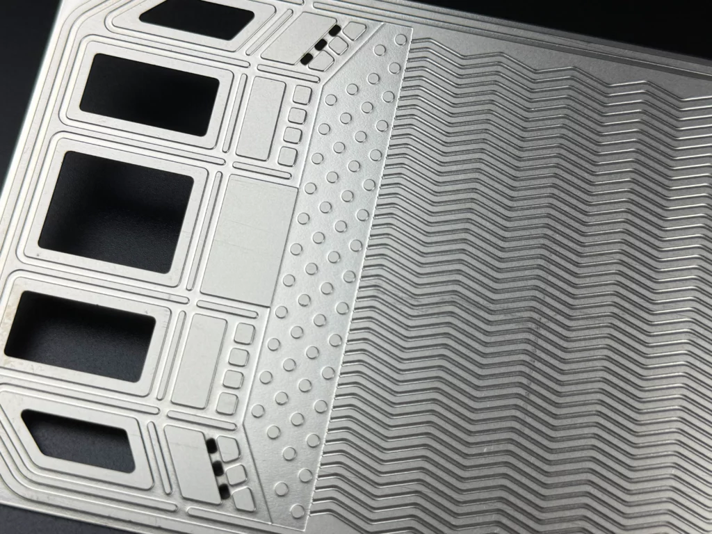
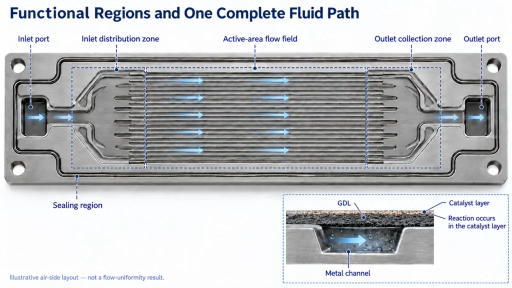
For layout review, divide the plate into the following functional regions. Their boundaries may be integrated into the geometry rather than marked by separate components.
| Region | Layout task | Main connection |
|---|---|---|
| Inlet port | Admit the designated fluid | Supply manifold to local passage |
| Inlet distribution zone | Spread flow toward the active area | Local inlet to channel entrances |
| Active-area flow field | Carry fluid across the working area | Inlet distribution to outlet collection |
| Outlet collection zone | Gather departing streams | Channel exits to local outlet |
| Sealing region | Define intended fluid boundaries | Plate, gasket and neighboring layer |
The inlet and outlet distribution zones have their own flow-distribution tasks. They should receive attention alongside the central channel pattern.
The flow field supplies reactants to the membrane electrode assembly, or MEA. Electrochemical reactions occur in the catalyst layers next to the gas diffusion layers, rather than inside the metal grooves themselves.
Follow One Fluid from Inlet to Outlet
Trace one circuit before examining the others. For the reference air circuit, follow the supply manifold, local inlet, distribution zone, active-area channels, collection zone and exhaust manifold.
The supply and exhaust manifolds connect the stack-level flow with the individual cell passages. Mark these connections on the relevant face and sectional views.
Repeat the exercise separately for hydrogen and coolant. A shared drawing location does not establish a shared fluid connection.
How Do Ports and Manifolds Feed the Plate?
Stack Manifolds vs Local Plate Distribution
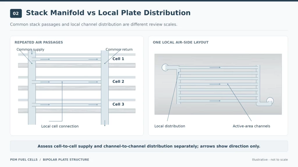
In an internally manifolded design, aligned plate openings form common passages through the stack. Local connections then feed the appropriate plate regions. The manifold arrangement and plate geometry must be considered together.
There are two distribution questions:
- Does the stack manifold supply the different cells adequately?
- Does each plate distribute its incoming flow across the active area?
These questions concern different scales. Stack entrance geometry, including the inlet pipe and end-plate configuration, can influence cell-to-cell distribution. A well-arranged local transition zone cannot by itself establish uniform supply throughout the stack.
During review, label the common manifold and local distribution region separately. This prevents a drawing comment about “the inlet” from referring to two different features.
Port Position Does Not Define the Entire Flow Path
“Same-side” and “opposite-side” describe locations, but a complete flow description also needs the inlet–outlet pairing and direction through each circuit.
Different gas inlet and outlet configurations can be evaluated while retaining the same underlying channel design. Direction should therefore be read from the assigned connections, not from an unlabeled outline.
Give hydrogen, air and coolant their own arrows. State which face or internal space each arrow represents. Any claim that one arrangement performs better should retain the operating conditions used for the comparison.
What Happens in the Inlet and Outlet Transition Zones?
Spreading Flow Across the Active Area
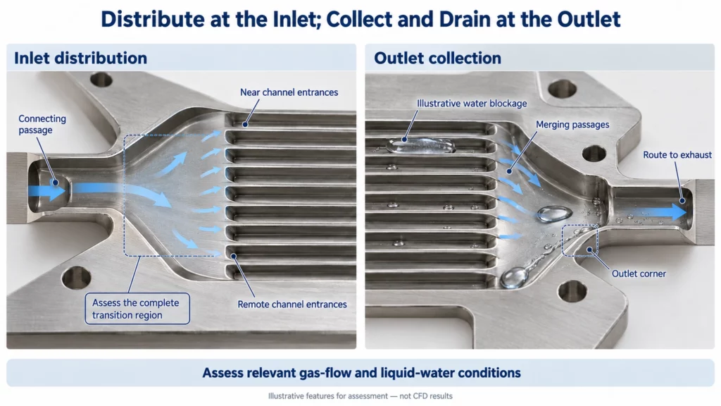
The inlet transition zone connects a relatively limited entry region to the wider flow field. Its geometry can affect how reactants reach different channel entrances.
The primary distribution structure can influence overall flow uniformity, while smaller features influence local distribution. This makes the transition region a design task beyond choosing a central channel pattern.
For a drawing review, ask:
- Which branches are nearest to the supply opening?
- How are the remote channel entrances fed?
- Are there narrow connecting passages or poorly supplied corners?
- Has the complete distribution region been included in flow assessment?
Use these questions to identify features requiring analysis. Do not treat an attractive or symmetrical plan view as proof of uniform distribution.
For channel width, depth and related performance trade-offs, see our guide to bipolar plate geometry and fuel cell performance.
Collecting Flow and Removing Water at the Outlet
The outlet region gathers flow leaving the active-area channels. Its behavior also depends on the liquid water present.
Stagnant gas regions around outlet distribution features can increase liquid retention under the studied conditions. The outlet therefore deserves its own assessment instead of being accepted automatically as a mirrored inlet.
Water can also alter how flow divides between channels. Measured flow maldistribution associated with water blockage shows why dry-flow behavior alone cannot establish performance during two-phase operation.
Review outlet corners, merging passages and the route toward the exhaust. Compare distribution and pressure loss under the relevant flow and water conditions.
A transition zone redistributes or collects a designated fluid. It should not be interpreted as a chamber for mixing hydrogen, air and coolant.
How Are Hydrogen, Air and Coolant Kept Separate?
Three Circuits with Defined Connections
For the liquid-cooled reference assembly, trace each circuit independently:
| Circuit | Intended route | Boundary to preserve |
|---|---|---|
| Hydrogen | Hydrogen supply, anode-side flow field and hydrogen return | Separation from air and coolant |
| Air | Air supply, cathode-side flow field and exhaust | Separation from hydrogen and coolant |
| Coolant | Coolant supply, internal cooling space and return | Separation from both reactant circuits |
The separate anode, cathode and coolant passages must remain connected along their own intended paths. Hydrogen is not normally routed through an air channel to reach the coolant circuit.
Product water and coolant also have different roles. Water produced by the cathode reaction moves through the electrode and gas-transport structure. Liquid coolant circulates through a separate cooling passage.
Elastomeric Seals and Port Isolation
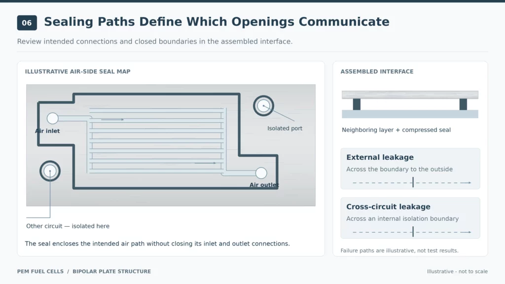
Elastomeric seals on bipolar plates help define fluid boundaries. Their placement must be reviewed around ports as well as along the plate perimeter.
At gas and liquid interfaces, local sealing-groove arrangements can differ from those used elsewhere on the plate. Evaluate the seal with the neighboring plate and MEA geometry in their assembled positions.
For each opening, identify which layer should communicate with it and which interfaces should remain closed. Distinguish leakage to the outside from leakage between internal circuits.
A correct port label alone does not verify this isolation. The sealing path and component interfaces need their own review.
Check the Coolant Path in the Assembled Plate
A metallic bipolar plate can be made from two joined half-plates. Their inward-facing geometry creates the internal coolant flow space, while the outward gas-flow surfaces serve neighboring cells.
Consequently, a single-face drawing cannot fully establish the coolant route. Inspect both halves together, including connecting passages and possible obstructions.
Confirm that coolant can travel from its inlet to its outlet without entering either gas circuit. The relevant geometry is the completed assembly, including its joining and sealing boundaries.
What Should Be Checked Before an Etched Layout Is Released?
Translate the circuit description into a drawing review. Use the following questions before committing to an etched fuel cell plate:
- Does every inlet and outlet identify its intended circuit?
- Are the supply and return connections paired correctly?
- Can each path be traced through the assembled geometry?
- Are the required sealing boundaries continuous and defined?
- Have both distribution and collection regions been assessed?
- Are flow behavior and circuit isolation covered by separate validation?
Pressure-drop and two-phase flow measurements examine flow behavior. Sealing experiments examine boundary integrity. Include both where the project requires them.
For chemical etching, provide face labels, sections, port identities and connection requirements alongside dimensions. Identify the intended joining and surface-treatment sequence.
Our bipolar plate requirements and testing guide covers the broader acceptance framework. Keep detailed channel-topology comparisons in the separate flow-field types guide.
TMNetch Manufacturing Example: Two-Sided, Dual-Depth Etching
A published TMNetch bipolar plate example illustrates a 2.0 mm plate with channel depths of 0.6 mm and 0.4 mm on one face, and 0.5 mm on the opposite face.
The example concerns manufacturing geometry. The published description does not assign those depths to specific fluid circuits or provide corresponding flow-distribution and cross-leakage results.
For a comparable layout review, label what each recess carries and show its connection to the appropriate port. Then assess the complete assembly and its isolation boundaries.
Different depths can be specified on a drawing, but the fluid-routing meaning must also be explicit. This keeps dimensional approval connected to the intended function without treating geometry alone as performance validation.
FAQs About Bipolar Plate Structure
Do all bipolar plates have six ports?
Not necessarily. Determine the port count from the actual manifold and cooling arrangement, then identify the function of every opening.
Is the transition zone a mixing zone?
It distributes or collects a designated stream. Its flow-distribution function does not imply that hydrogen, air and coolant should mix.
Are product water and coolant part of the same circuit?
They have different paths in the reference design. Reaction-water transport and internal liquid cooling should be identified separately on the circuit drawing.
Conclusion: Check Every Flow Path and Isolation Boundary
A useful bipolar plate structure review follows each fluid from supply to return and checks every boundary along the way. Give ports, transition regions and internal cooling spaces the same attention as the active-area channels.
If you are evaluating chemical etching for custom metal bipolar plates, send TMNetch your material grade, port map, face and sectional drawings, and sealing requirements. Include the intended coolant route and acceptance conditions so manufacturing and assembly interfaces can be reviewed together.