One crucial part of fuel cells is the bipolar plate, but people often overlook it. Instead of being flat, they are made to carry gas and coolant, which are important parts of a fuel cell’s operation. If the city represents the fuel cell stack, the bipolar plates work as the traffic engineers to keep everything well organised. Lets discuss Structure of Bipolar Plates in Fuel Cell Plates.
The work of Bipolar Plates
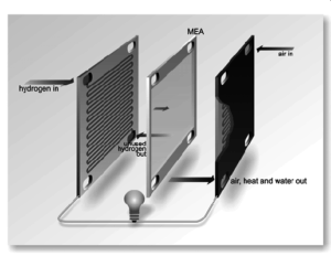
In a PEMFC, bipolar plates take care of several crucial duties.
Issue the fuel and both of the two oxidant gases, which are hydrogen and oxygen.
- Get rid of the water made during the reaction.
- Pass an electrical current from cell to cell.
- Control heat with the use of integrated coolant tubes.
The performance, durability, and efficiency of the fuel cell depend on the way the fuel cell is constructed.
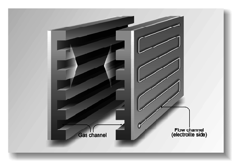
Structure of Bipolar Plates in Fuel Cell Plates
Bipolar plates normally have three main parts that carry out different functions.
Area for Inlet and Outlet
The first stage is the Transition Zone, which exchanges elements.
Reaction Area (the Flow Field Zone)
Richards and Kinn hardly agreed on heat entry, movement, and exit mechanics. The area is divided into an inlet and an outlet. You can see it as an invitation from the plate to you. It is responsible for directing the hydrogen, oxygen (air), and cooling water both in and out.
Functions:
- Determines how fluids can move in and out of a living organism
- Plays a role in setting the pressure difference across the plate
- Ensures there is not too much or too little water to avoid each extreme.
- Contributes to the way current is shared within the cell.
If the angle of this feature is not perfectly accurate, it may stop the system from operating properly.
Transition zone (Zone of Mixing)
The zone acts like a roundabout at an intersection with heavy traffic. It allows gases and water to reach the active areas efficiently.
Design Challenges:
A lot of pressure is lost when an expansion J-tube has to maneuver through a U-turn.
The traffic must be shared equally among several channels. They can be as simple or as complex as these things: A point flow transition refers to a way of delivering a significant amount of information in a single payment. You will need fan flow transition (wide paneling).
If it’s done properly, you’re prepared to do your best as you react.
Reaction Area (Flow Field Zone)
This area is where the reaction (flow fields) takes place.
Here, you get to experience the most exciting moments. In this part of the fuel cell, there is the most involvement with the MEA (Membrane Electrode Assembly).
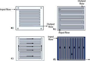
A look at how developers have arranged their game flow fields.
Straight channels : They are basic and provide a low resistance to currents
S-channels: Somewhat complex, more effective at mixing.
Serpentine channels help remove water and are stronger than even straight channels.
Channel Shapes:
It is straightforward to create a square cross-section.
It cuts the pressure drop, making controlling the flow simpler.
The layout used here impacts the amount of power the stream produces, how water is managed, and how long it can last.
Sharing inlets and outlets
There are two types of bipolar plates depending on their port placement.
All of them are on the same side.
There are inlets found on various sides of the peninsula.
Both air inlets are positioned on the same side. All the water, air, and sustenance enter from the same side.
This framework reduces complications in the stack and adds the ability to:
Co-current flow : Gases travel in the same direction.
Gases are pushed in the opposite directions.
Pros :
- Easy integration
- Processes that simplify the route of channels
Cons:
- May prevent the creation of equal distribution
- It may result in unequal room temperatures.
Inlet Arrangement
The blades are set up on both sides of the shaft, called a Different-Side Inlet Configuration.
In this design, the tap and faucet are set opposite each other. Even though it’s a harder concept to design, it often turns out better.
Thermal management
Fluid balance
Typical Layout:
The hydrogen channel is connected to the water channel through air channels
It is smooth, like a sandwich when it is evenly cooled in the center.
Flow Channel Geometry
The way channels are designed serves a function, not only how they look.
Common Shapes:
The shape is easier to form compared to other channels and it moves liquids with minimal disturbance.
Trapezoidal channels: Make dead zones smaller and improve the smooth transition of waters.
This affects the motion of the reactants, the draining of water and the distribution of current in the pipeline.
How to Design Cooling Water Channels
Cooling relates to heat, but also touches on other issues, including:
- Membrane hydration
- Proton conductivity
- The pushing and pulling forces can damage plates.
Designers usually insert coolant channels between gas channels to ensure even and consistent temperature inside the reactor.
Issues Arising in the Transition Zone
It is an area that experiences many ups and downs. Taking a sharp turn causes more pressure to escape from the pipe. Nevertheless, this can be solved by engineers with:
Rounded corners
Gradient channels
Nearly all improvements are geared toward improving performance at lower losses.
Innovative Designs
Modern plates are being designed so that the transition zone can be completely removed. They are instead based on:
- Channels that meaner from the inlet to the outlet
- There are flow separators included within each field.
- Doing so simplifies the design and can also increase both the reliability and speed of production.
Things to Think About When Designing
- Designers have to focus on several important objectives.
- See to it that all parts of the tank receive equal amounts of gas and liquid.
- Prevent the pressure from dropping across the plate.
- Ensure MEA is always hydrated to maintain proper conductivity.
- Help the quick drying of the area
So, bipolar plates must handle many tasks and are good at them.
Conclusion
In the world of fuel cells, bipolar plates do not get the recognition they deserve. How the inlets, outlets, flow fields, and transitions are put together in a fuel cell determines much of how it works. No matter if you want better power, improved water flows, or controlled heat, the first step must be a smart plate design. The next time you hear about fuel cells, remember to recognize the plates involved in their progress.