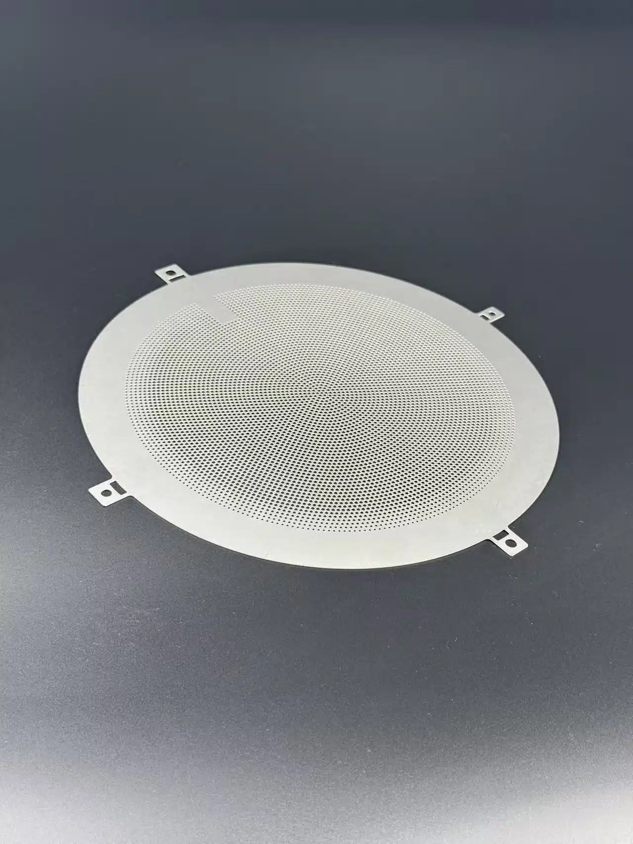

Choose bipolar plate material by defining the operating conditions, plate geometry and contact requirements first. Then compare complete material systems: the base material, its surface or binder system, and the condition of the finished plate.
In a proton exchange membrane fuel cell, or PEM fuel cell, bipolar plates separate neighboring cells, conduct current and provide reactant-flow channels. Material selection must support those jobs together. A conductivity value or raw-material price cannot answer the whole question.
Key takeaways
- Define the application before ranking materials.
- Compare graphite, graphite-polymer and metallic plates in their intended finished condition.
- Use the same test conditions when comparing candidates.
- Review etching feasibility after shortlisting a metal, then qualify it for fuel-cell service.
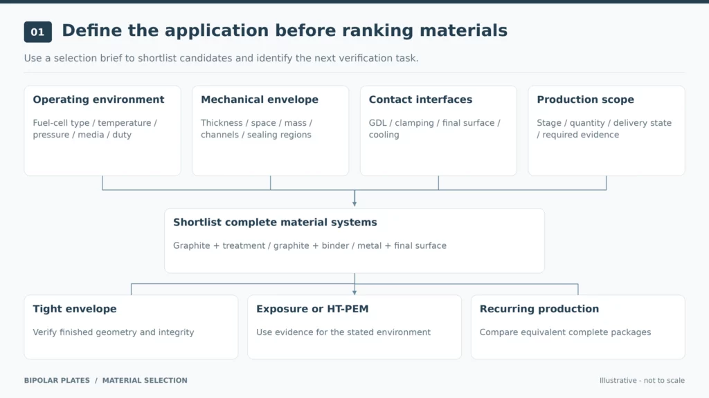
Start with the Application Requirements
Write a short selection brief before requesting samples. Include:
| Requirement | Information to define |
|---|---|
| Operating environment | Fuel-cell type, temperature, pressure, media and expected load or start-stop conditions |
| Mechanical envelope | Plate thickness, available space, mass target, channel geometry and sealing areas |
| Contact interfaces | Gas diffusion layer, clamping conditions, surface state and cooling interfaces |
| Production scope | Development stage, quantities, delivery condition and required evidence |
Do not use an industry label as the specification. “Automotive” or “stationary power” still leaves the operating environment and acceptance criteria undefined.
Keep low-temperature PEM and high-temperature PEM requirements separate. HT-PEM plate materials and molding processes have been developed and tested for that specific environment. Do not transfer a material approval between operating regimes without reviewing its scope.
For more detail on the assembly interfaces, see our guide to bipolar plates in PEM fuel cells.
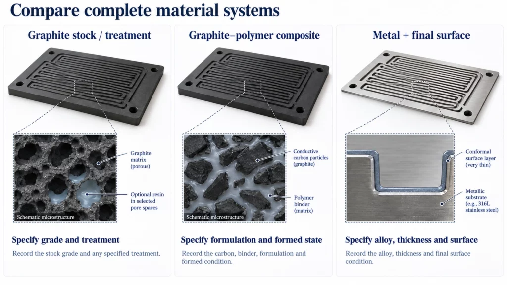
Compare Complete Bipolar Plate Material Systems
Graphite Stock and Impregnated Graphite
For a machined graphite candidate, specify the stock grade and treatment state. If resin impregnation is used, identify the resin system as part of the material specification.
In resin-impregnated expanded-graphite plates, pore structure and impregnation conditions affect the resulting electrical, mechanical and gas-barrier properties. “Graphite” alone therefore does not define the product being evaluated.
Ask for results from the proposed material condition, rather than assuming that all graphite plates need the same treatment. Our graphite bipolar plate guide covers the preparation routes in more detail.
Graphite-Polymer Composites
These plates combine conductive carbon material with a polymer binder. In epoxy and expanded-graphite composites, composition influences electrical conductivity and flexural performance.
Compare the formulation and formed condition, not just the graphite percentage. Identify the binder, forming route and relevant test direction. A favorable conductivity result should not replace the mechanical or gas-tightness evidence required for the finished plate.
Metals with a Defined Surface Condition
For a metallic candidate, record the alloy grade, thickness and surface specification together. Stainless steel and titanium belong within this metal branch; 304 and 316L are a further choice within stainless steel.
For example, 316L is a low-carbon, molybdenum-alloyed stainless steel. That composition identifies the grade, but does not by itself approve a finished fuel-cell plate.
Use our metallic bipolar plate guide for the metal-system review. Continue to 304 vs 316L or titanium bipolar plates when the shortlist reaches that level.
Which Material System Matches Your Application Priorities?
Use the following table to build a shortlist and define the next verification task. It is a screening framework, not a final material approval.
Material-specific manufacturing routes include graphite-resin systems and coated stainless-steel foil systems. Thin graphitic foil-based plates are another development route. Compare each candidate with its proposed manufacturing and surface condition attached.
| Application priority | Candidate direction | Verify before selection |
|---|---|---|
| Tight thickness, space or mass limits | Evaluate a thin metallic design; retain thin graphite-composite alternatives where relevant data support them | Finished geometry, local wall thickness, mechanical integrity, sealing and contact behavior |
| Chemical exposure or start-stop duty dominates | Screen the complete substrate–surface or graphite–binder system against the specified exposure | Corrosion, surface changes, contact resistance and mechanical condition after testing |
| HT-PEM or a changed operating regime | Start with systems supported by evidence for that environment | Binder, impregnant or coating compatibility, followed by component and cell validation |
| Development requires repeated channel changes | After shortlisting a metal, review the etched drawing; define differences if using machined graphite as a reference | Grade, stock thickness, channel depths, remaining wall thickness and surface condition |
| Stable design and recurring production | Compare complete material–manufacturing packages meeting the same acceptance requirements | Processing, surface treatment, joining, inspection, tooling and yield assumptions |
Avoid turning these directions into shortcuts such as “all mobile systems need titanium” or “all long-life systems need graphite.” Make the decision against the requirements in the first table.
Once the material family is narrowed down, use the relevant branch guide for the detailed choice. Keep manufacturing-method purchasing decisions in the bipolar plate process comparison.
Resolve the Tradeoffs That Can Change the Decision
Bulk Conductivity Is Not Contact Resistance
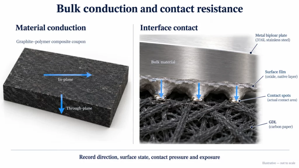
Bulk conductivity concerns current passing through a material. Contact resistance concerns the interface between contacting components.
On stainless steel, passive-film formation can increase resistance at the carbon-paper interface. A good bulk conductivity value therefore cannot stand in for a measurement of the finished contact surface.
Require comparable surface conditions, contact pressure, measurement direction and exposure state. Label in-plane and through-plane results clearly. For graphite-based systems, plate characterization includes both directional conductivity and interfacial measurements; keep those results separate in the comparison.
Evaluate the actual substrate–surface combination. Carbon-coated titanium foils, for example, are a specific material system evaluated for PEMFC bipolar-plate use. Their results should not be assigned to every titanium grade or surface condition.
Apply the same discipline to graphite and polymer systems. Identify whether a report covers a material coupon, a formed plate or an operating cell.
For your shortlist, request evidence relevant to the proposed channel features, sealing areas, clamping conditions and operating exposure. Do not infer complete-plate durability from one material property. Our corrosion-resistance guide covers the exposure and failure questions in more detail.
Compare Finished-Part Cost
Request quotations against the same delivery scope. Separate material, feature production, surface treatment, joining, inspection and tooling costs.
Manufacturing cost assessments distinguish these process-chain contributions. Use current project quotations for the actual decision, with quantities and yield assumptions stated. Do not convert an older production model into a universal price ranking.
Check Etching Manufacturability After Shortlisting a Metal
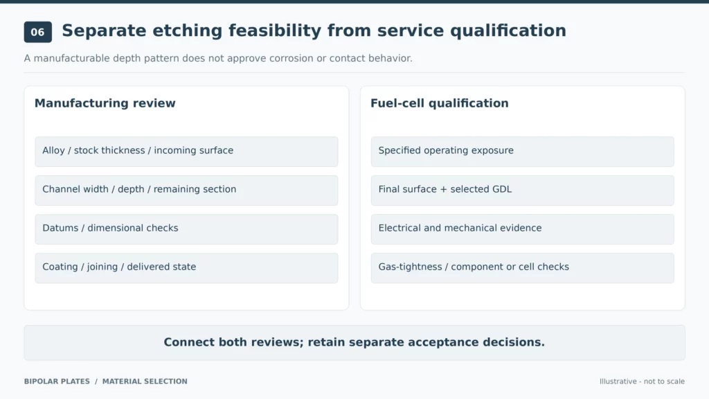
Photochemical machining removes selected metal through a photoresist-defined pattern. It establishes a manufacturing route; it does not establish long-term compatibility with the fuel-cell environment.
For an etching review, provide:
- Material grade, stock thickness and incoming surface condition.
- Channel width, depth map and required remaining wall thickness.
- Critical dimensions, datums and inspection requirements.
- Subsequent coating, joining and sealing requirements.
- The condition in which the part must be delivered.
Review these items together. Keep any material approval separate from approval of the etched geometry and subsequent surface process.
Our guide to chemically etched bipolar plate features covers that manufacturing interface. The broader bipolar plate manufacturing process explains the sequence through quality handover.
TMNetch Example: Reviewing a Dual-Depth Metal Plate
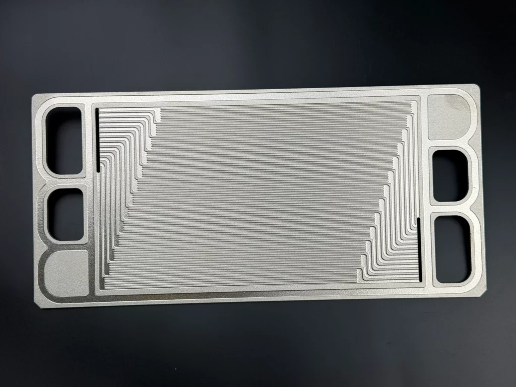
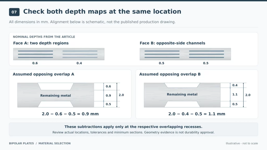
A published TMNetch manufacturing example specifies a 2.0 mm plate with 0.6 mm and 0.4 mm channel depths on one face, and 0.5 mm channels on the other.
For material selection, use this as a geometry-review example. After shortlisting an alloy, map the opposing channel locations and identify the critical remaining sections. Ask the manufacturing team to confirm those sections, achievable dimensional requirements and the proposed inspection method.
Next, define the surface treatment and exposure tests for that alloy. Approval of the depth pattern should not be used as approval of corrosion resistance or contact behavior.
Evidence scope: this is TMNetch’s publicly documented manufacturing example, not a customer durability-test result. It does not establish a universal depth capability for every material.
Qualify the Shortlist Before Releasing a Specification
Use a compact approval process:
- Align the comparison. Define the operating environment, specimen geometry, surface state, contact conditions and test methods.
- Identify the tested product. Record whether each result applies to stock, a treated coupon, a finished plate or a cell assembly.
- Close the relevant gaps. Request the missing electrical, mechanical, exposure or gas-tightness evidence.
- Release a defined material system. Record the approved grade or formulation, treatment state, drawing revision and acceptance criteria.
- Review later changes. Define which material, surface or process changes require reassessment.
Material formulation, manufacturing and component qualification are connected activities in PEM bipolar-plate development. Keep that connection visible in the approval record.
For the measurement framework, use our bipolar plate requirements and test-method guide.
FAQs
What Is the Best Bipolar Plate Material for a PEM Fuel Cell?
Select the material system that meets your defined operating, structural, contact and manufacturing requirements. Compare candidates under equivalent conditions before making the cost decision.
Is Graphite the Same as a Graphite-Polymer Composite?
Not necessarily. Specify whether the product is graphite stock, impregnated graphite or a graphite-polymer formulation. These descriptions identify different aspects of the material and preparation route.
Does Choosing an Etchable Metal Mean It Is Ready for Fuel Cell Use?
No. Etching feasibility addresses manufacture of the geometry. Fuel-cell qualification still needs to cover the specified alloy, surface condition, assembly and operating environment.
Conclusion
Start with application requirements, shortlist complete material systems, then verify the proposed finished condition. Keep material approval and manufacturing feasibility connected throughout the decision.
Shortlisting stainless steel or titanium? Share the grade, thickness, channel drawing, surface requirements and test criteria with TMNetch for an etching manufacturability review.