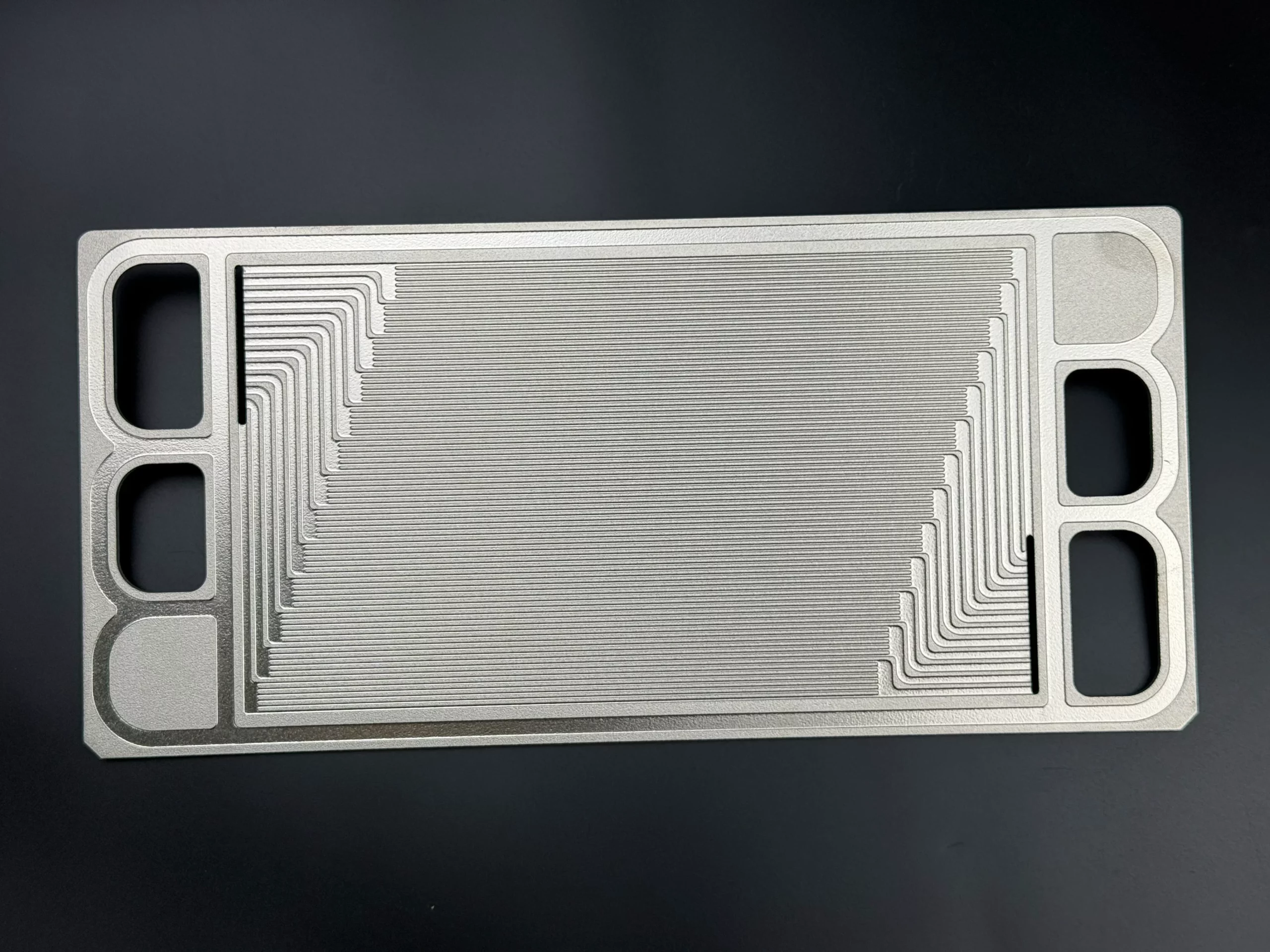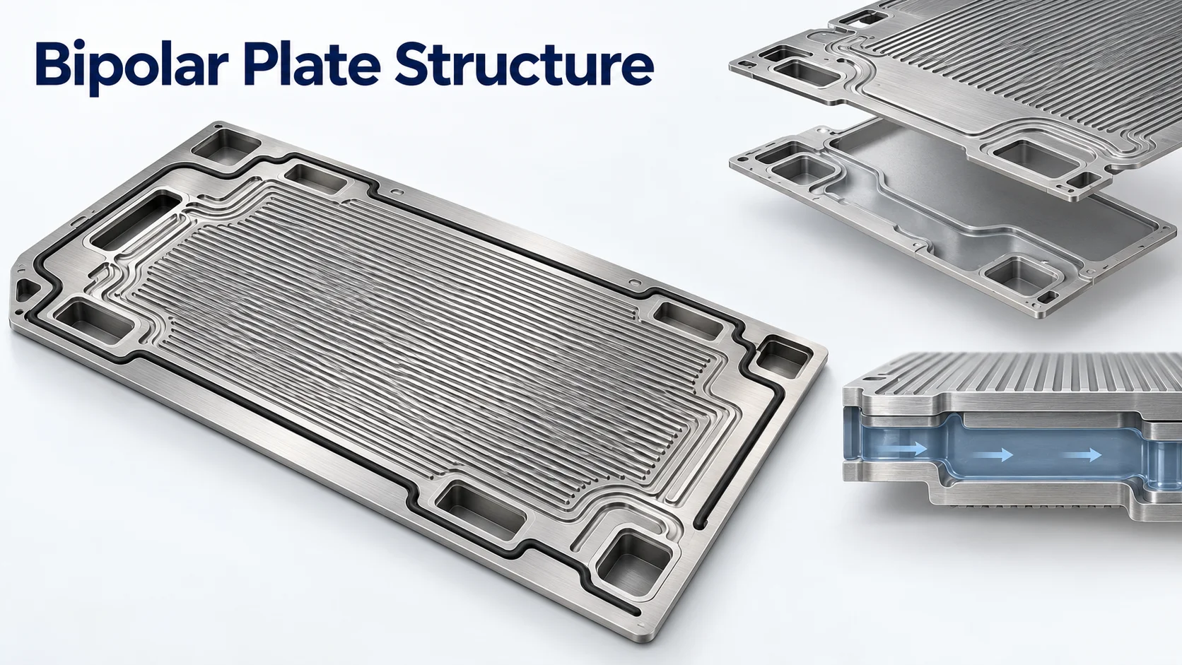

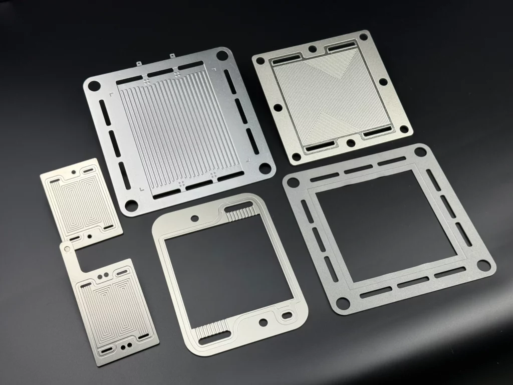
A PEMFC bipolar plate connects adjacent cells electrically while providing separate fluid paths. In proton exchange membrane fuel cells, it also interfaces with the gas diffusion layer (GDL), seals and, in liquid-cooled designs, the cooling circuit. Evaluating bipolar plates for PEM fuel cells therefore requires a review of the assembled interfaces under defined operating conditions.
This guide focuses on conventional low-temperature PEMFCs. For broader background, see bipolar plate functions and material categories. The task here is to connect operating inputs with contact, sealing and assembly decisions.
Key takeaway:
Define the operating environment first. Then evaluate the final plate surface with the selected GDL, gasket arrangement and cooling design. Material identity and dimensional conformity are important inputs to that review.
Which PEMFC Operating Conditions Should Be Defined First?
Temperature, Humidity and Operating History
Conventional low-temperature PEM fuel cells commonly operate around 80°C. Use that figure as background, then specify the actual temperature range, operating points and transient conditions for the project.
Define inlet humidity or dew point together with gas temperature and pressure. Include the startup, shutdown and load changes that the qualification plan must represent.
The membrane requires adequate hydration, while reactants still need access to the catalyst layers. Membrane hydration and inlet humidification therefore belong in the operating specification. Removing water as quickly as possible is not a complete water-management objective.
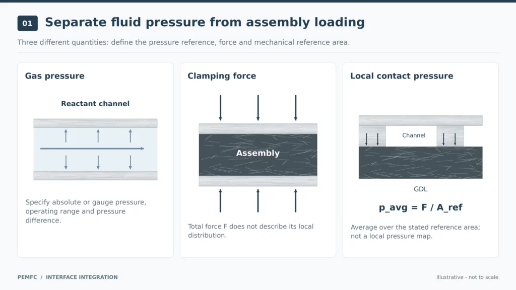
Separate Gas Pressure from Assembly Compression
Use separate entries for fluid pressure, mechanical loading and electrochemical exposure.
| Input | What to specify |
|---|---|
| Reactant pressure | Absolute or gauge pressure, operating range and relevant pressure differences |
| Assembly loading | Clamping arrangement, component compression and contact-area definition |
| Surface exposure | Temperature, medium, potential reference, duration and cycling conditions |
Gas pressure and local plate–GDL contact pressure describe different conditions. Record the reference area when reporting a mechanical pressure. A total clamping force does not describe its local distribution.
For corrosion testing, identify the electrode reference and imposed potential. The local environment of a metallic bipolar plate can differ from a fully immersed screening test, and its corrosion potential need not equal the nearest catalyst electrode’s potential.
How Do Bipolar Plates and GDLs Work Together in a PEMFC?
Explain the Different Jobs of the Plate, GDL and Membrane
The PEMFC component arrangement places the GDL between the flow-field plate and the catalyst layer. Reactants pass from the channels through the porous GDL toward the reaction sites.
| Component | Role at the interface |
|---|---|
| Bipolar plate | Provides flow channels, electrical connection and physical separation between cells |
| GDL | Supports reactant transport, product-water removal and electrical contact |
| Catalyst layers | Provide the sites for the electrode reactions |
| Proton exchange membrane | Conducts protons between electrodes while blocking electrons |
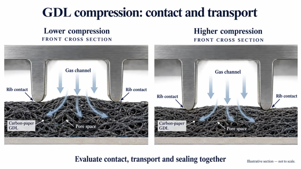
The raised portions between channels are called ribs or lands. These contact the GDL, while the channel openings provide space for gas transport.
Where a GDL includes a microporous layer, that layer faces the catalyst side. It is part of the diffusion-medium arrangement and should be distinguished from a functional coating on the metal plate.
Why Lower Contact Resistance Is Not the Only Goal
Clamping changes the interface mechanically and electrically. In experimentally evaluated GDLs, compression reduced contact resistance while also reducing gas permeability.
The channel-and-rib pattern also creates uneven compression. GDL beneath a rib experiences a different constraint from material beneath a channel. As a result, one average compressed thickness may not represent every local region.
The engineering objective is to evaluate electrical contact and transport together. A contact-resistance improvement alone does not establish that the complete assembly performs better.
Define the GDL product, loading conditions and compressed state before comparing plates. If the gasket or plate geometry changes, review whether the original contact comparison still represents the new assembly.
Define What Must Be Matched at the Interface
Start the interface review with a controlled set of inputs:
- GDL specification, thickness and orientation;
- Plate contact regions and geometric references;
- Final plate surface or coating condition;
- Applied load, reference area and assembly arrangement;
- Required electrical, transport and post-assembly checks.
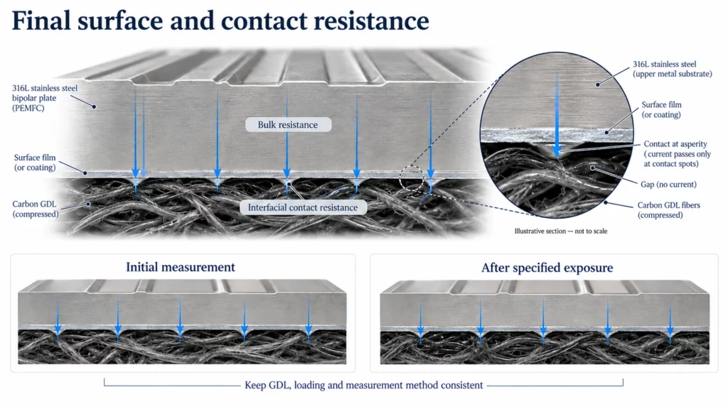
Distinguish interfacial contact resistance (ICR), meaning resistance associated with the contacting surfaces, from the bulk resistance of the material. Keep the measurement configuration with every reported result.
For a design comparison, change one input at a time where practical. Otherwise, a difference attributed to the plate may also reflect a changed GDL, gasket or loading arrangement. This is a proposed comparison method, rather than a universal test protocol.
How Should Plate Materials and Coatings Be Evaluated at This Interface?
Evaluate the Final Surface, Not Only the Base Material
A material certificate identifies the supplied alloy. Evaluating the finished plate–GDL contact requires additional evidence about the actual surface.
For stainless steel, passive-film formation can increase contact resistance against carbon paper. Corrosion resistance and electrical contact therefore need to be considered together.
Evaluate the plate in its intended delivered condition: bare, surface-treated or coated, as specified. Record subsequent cleaning and handling requirements so the tested condition can be related to the assembly condition.
For substrate and manufacturing considerations, use the separate guide to metallic bipolar plates for PEM fuel cells. The interface review should remain focused on the selected material and finished surface.
State Contact and Exposure Conditions with the Result
Make a contact-resistance result traceable to its test configuration. Request:
- Substrate grade and final surface condition;
- Contacting GDL or other counter-material;
- Applied load and contact-area definition;
- Measurement method and specimen identification;
- Exposure conditions and results before and after exposure.
Include temperature, medium, duration and potential reference where electrochemical exposure is involved. Clearly distinguish the initial surface measurement from the result after the specified exposure.
A useful comparison asks whether the selected surface maintains the required contact behavior under relevant conditions. It should not rank coatings using results obtained with incompatible methods or different counter-materials.
For example, a proposed surface-change review could keep plate geometry, GDL and loading constant while comparing the original and revised surfaces before and after the agreed exposure. Review dimensional acceptance separately. If the gasket or GDL also changes, record that as an additional variable instead of attributing the entire result to the surface treatment.
Keep coating selection linked to the application. Details of bipolar plate coating systems belong in a dedicated materials review; the approval question here concerns the final coated plate and its interfaces.
How Do Sealing and Cooling Interfaces Affect Plate Integration?
Review the Gasket and GDL as One Compression Arrangement
Elastomeric seals on bipolar plates form part of the assembled sealing arrangement. Their dimensions must be reviewed alongside the GDL and the plate’s sealing regions.
Sealing-gasket geometry and compression influence sealing performance in the evaluated assembly. Define gasket material, free dimensions, compressed dimensions and the relevant plate geometry before setting the assembly requirement.
For the project review, place the GDL and gasket dimensions on the same section drawing. Identify which surfaces establish the assembled gap and how the loading arrangement will be controlled.
If compression is changed to improve electrical contact, recheck the sealing arrangement and GDL state. Increasing clamp load should trigger a coordinated review, rather than an isolated electrical decision.
Specify the pressure difference that the seal must withstand, together with test conditions and acceptance criteria. An initial leak-test pass answers a defined test question; durability requires evidence covering the specified operating history.
Check the Coolant Circuit and Joined Plate Assembly
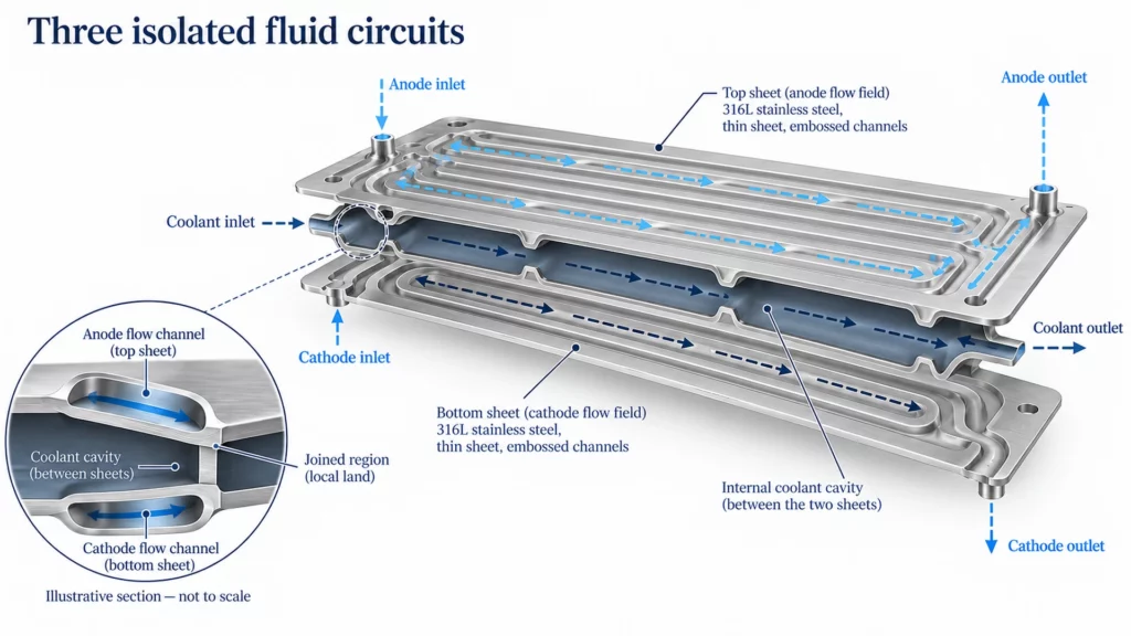
In a liquid-cooled metallic bipolar plate made from two half-plates, the assembly can contain separate anode, cathode and coolant flow fields. The internal coolant path must remain isolated from the external reactant paths.
Product-water removal and coolant circulation are different transport tasks. Keep their boundaries explicit in the drawing and test plan.
For the cooling interface, define inlet temperature, required flow, allowable pressure drop and pressure differences relative to adjacent circuits. Identify joined regions and the surfaces included in each test fixture.
A practical review should distinguish external leakage from leakage between circuits. Record which circuit was pressurized, which adjacent regions were monitored and what assembly condition was tested.
When joining or assembly changes, review the affected dimensions, flow paths and integrity checks together. This applies particularly when the change alters the boundary between coolant and reactant passages.
These checks form an interface-review framework. The responsible system designer should specify the acceptance values and required verification for the actual configuration.
What Should Be Validated Before a PEMFC Bipolar Plate Is Approved?
Match the evidence to the approval question. Dimensional inspection, surface evaluation and operating validation answer different questions.
| Approval question | Evidence to agree |
|---|---|
| Does the final surface suit the selected GDL? | Contact evaluation with defined surface, GDL and loading conditions |
| Do the gasket and plate assemble as intended? | Dimensional and assembly records plus specified leak tests |
| Does the cooling circuit meet the design requirement? | Flow, pressure-drop and circuit-integrity results under agreed conditions |
| Does the interface remain acceptable after exposure? | Relevant post-exposure measurements or single-cell/stack validation |
Use this table as a planning framework, with project-specific acceptance criteria. Define responsibility for each activity, particularly when etching, coating, joining and stack assembly are performed by different organizations.
For a leak test of bipolar plates, specify whether the test concerns a joined plate, a fixture-mounted component or an assembled cell. Keep the tested configuration identifiable in the report.
Detailed bipolar plate requirements and validation should provide the numerical limits and methods. Manufacturing approval should state which of those requirements have been verified and which remain for the next assembly stage.
Include change control in that handover. Identify which evidence must be reviewed when the GDL, gasket, coating or joining route changes. Retain the approved baseline, drawing revision and test configuration so the next team can distinguish an unchanged interface from one requiring renewed evaluation. This proposed workflow makes the scope of an approval visible.
TMNetch Case: Turning Functional Areas into Acceptance Criteria
In a previous TMNetch etching order, a customer questioned small connection points around the parts. The factory explained that these were intentional retaining tabs and that their size could be reduced where processing conditions allowed.
The customer accepted them provided they did not affect the finished part’s functional area. This documented retaining-tab case concerned general etched components, rather than a PEMFC performance trial.
Its relevance is the acceptance method: identify the feature and establish where it may remain. For a PEM fuel cell bipolar plate, apply that approach by clearly identifying GDL contact areas, sealing regions and joining surfaces. The proposed follow-up is a drawing-based agreement, with interface performance verified separately.
FAQs
Are bipolar plates and GDLs the same component?
No. The plate provides channels and electrical connection; the porous GDL sits between the plate and catalyst layer and supports transport and contact.
Does higher clamping pressure always improve PEMFC performance?
No. Evaluate electrical contact alongside GDL transport and gasket behavior. A suitable loading condition must be established for the selected materials and assembly.
Define the Interfaces Before Chemical Etching
Planning custom bipolar plates for a PEMFC? Share the operating conditions, material and final surface requirements, GDL and gasket arrangement, cooling interface and critical drawing dimensions with TMNetch.
Include who will coat, join and assemble the plates, together with the required manufacturing inspection records. These inputs support review of the etched geometry and acceptance requirements before sampling.
Use TMNetch’s chemical etching services to discuss the manufacturing scope within that defined interface and validation plan.