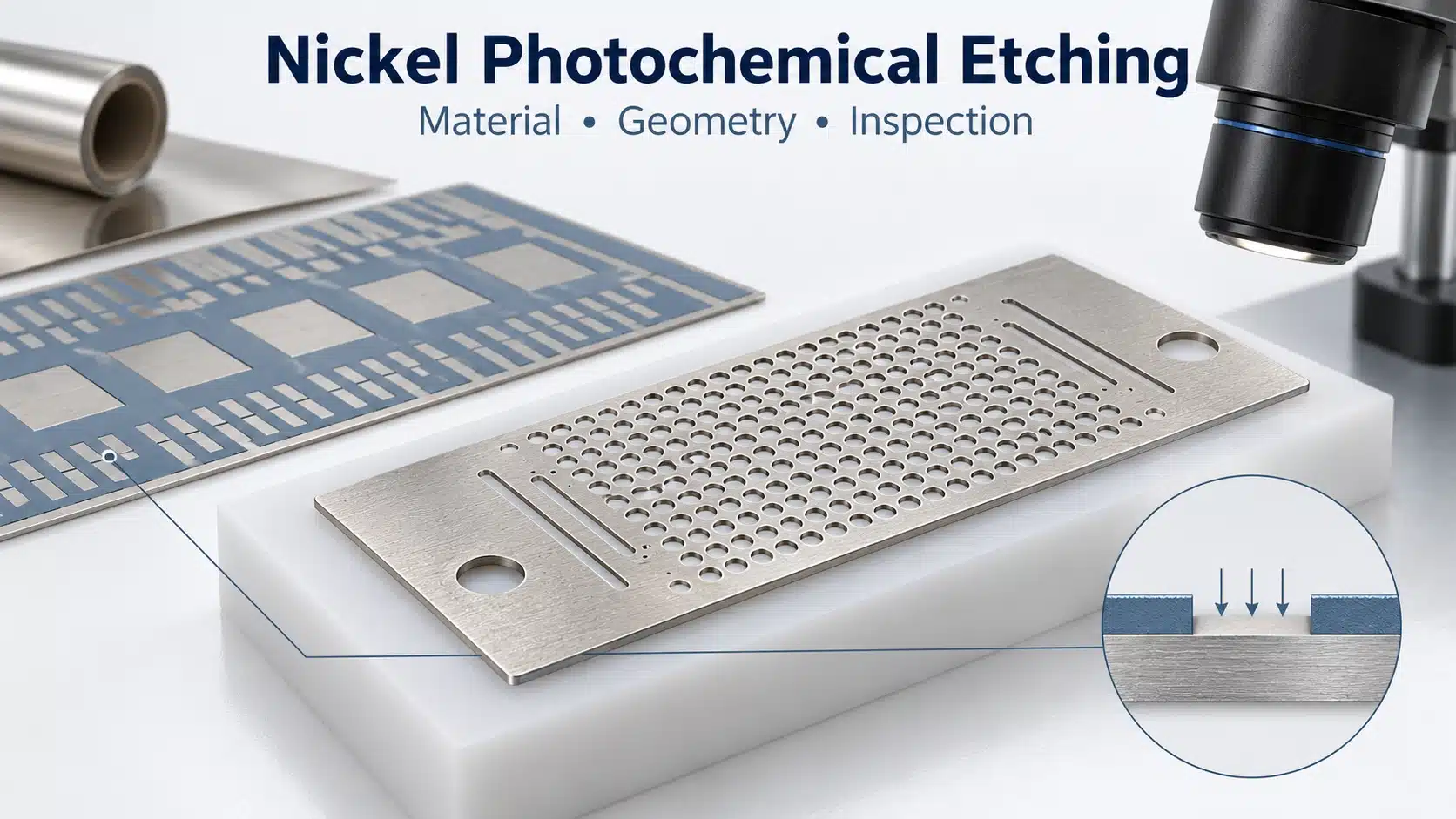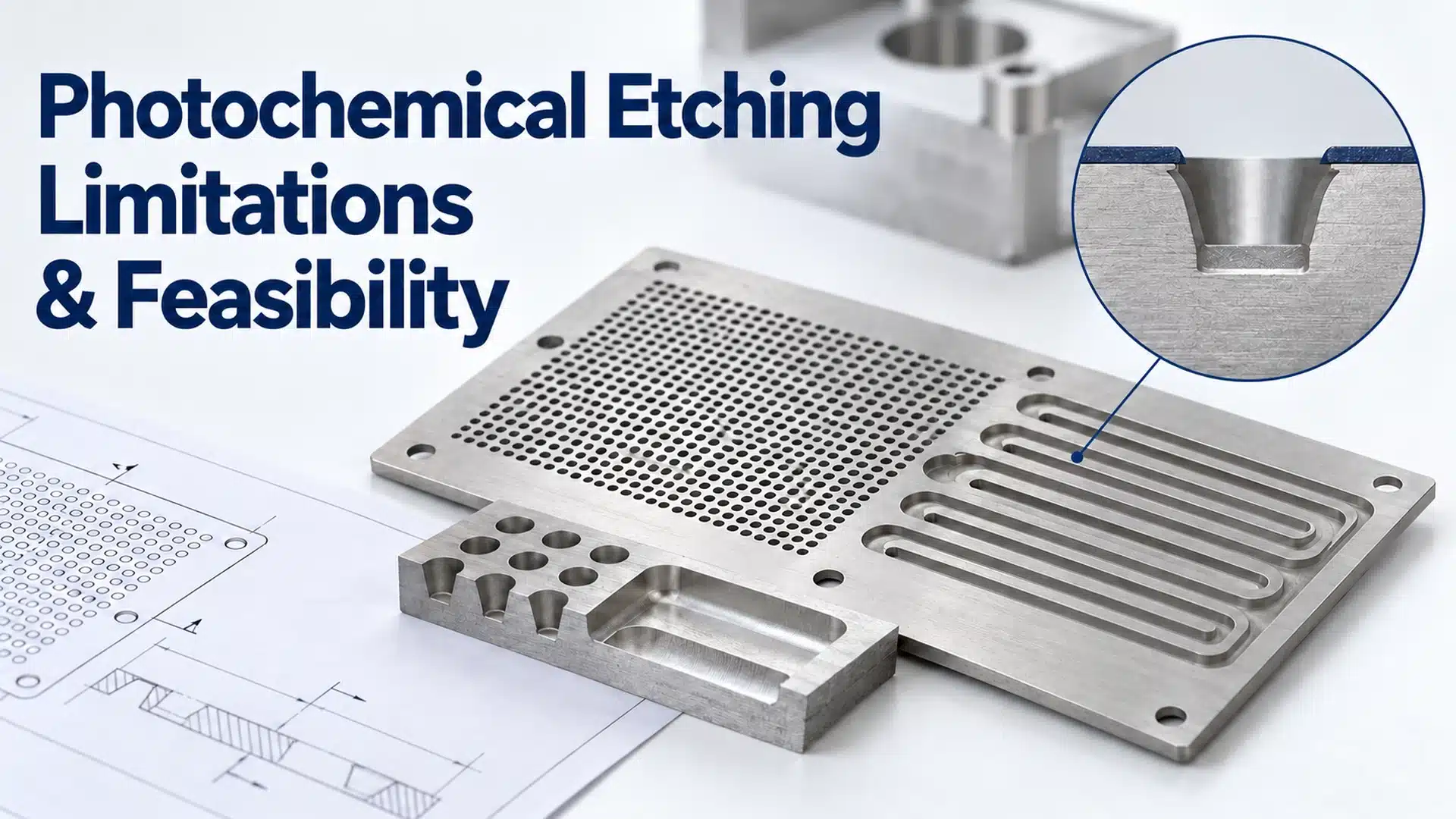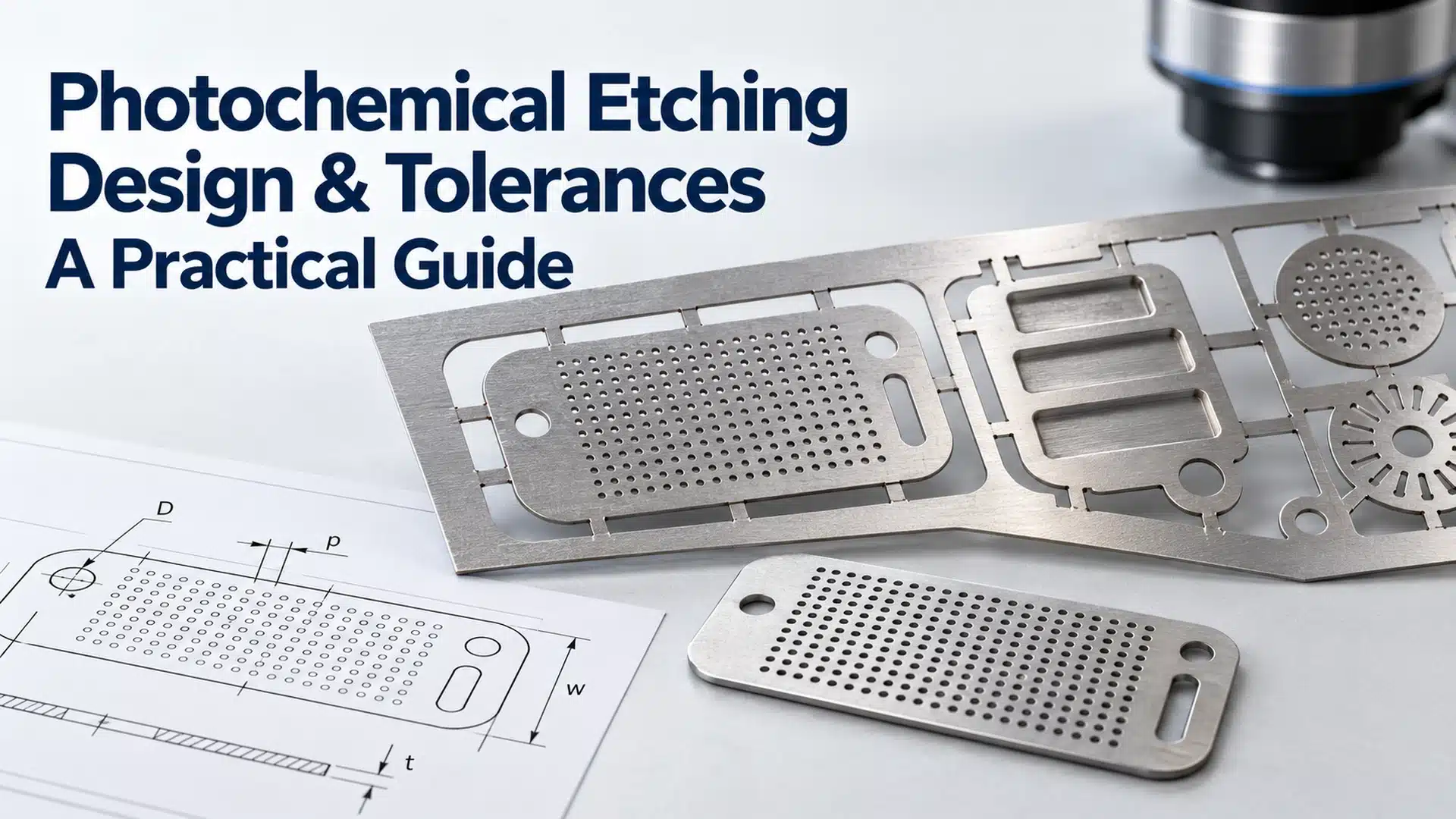

Chemical etching is usually the better fit for thin heat exchanger plates with dense, repeated or partial-depth flow features. Laser cutting is usually the better fit for thicker stock, large ports and simple through-cut profiles. A hybrid route often makes the most sense when one plate combines fine channels with a robust outer shape.
An early chemical etching services review should start with the drawing, alloy, thickness, channel geometry, joining method and volume. The goal is the lowest-risk route for the finished plate and bonded core.
10-Second Decision Summary
- Choose photochemical etching for a thin plate with hundreds or thousands of closely spaced channels, holes or manifolds, or for controlled partial-depth recesses.
- Choose laser cutting when the part is dominated by a perimeter, large ports or widely spaced through-slots, especially when the stock is beyond the etching supplier’s qualified thickness range.
- Consider a hybrid route when the same plate needs etched flow geometry plus laser-cut outer features or large openings.
- Do not decide from thickness alone. Feature depth, minimum web, cutting length, flatness, joining and inspection can change the answer.
Key Takeaways
- Etching processes an exposed pattern across a sheet; laser cutting follows a programmed path.
- Photochemical machining can create partial-depth and through-etched features in the same flat part.
- Laser cutting is strong for simple through-geometry; laser ablation is a separate micromachining operation.
- Etching avoids a thermal cutting zone but creates undercut. Laser edges may require control of heat effects, dross and burr.
- Neither process alone establishes the pressure rating of the completed heat exchanger.
What Is Being Compared?
Photochemical etching, also called photochemical machining, transfers a CAD pattern to photoresist. Exposed metal is removed chemically to form channels, ports, holes and profiles. A manufacturing study describes the process and cost stages.
Laser cutting uses a focused beam and assist gas to separate material along a programmed path. It is mainly a through-cut process. Blind features require a separate laser-micromachining or ablation window.
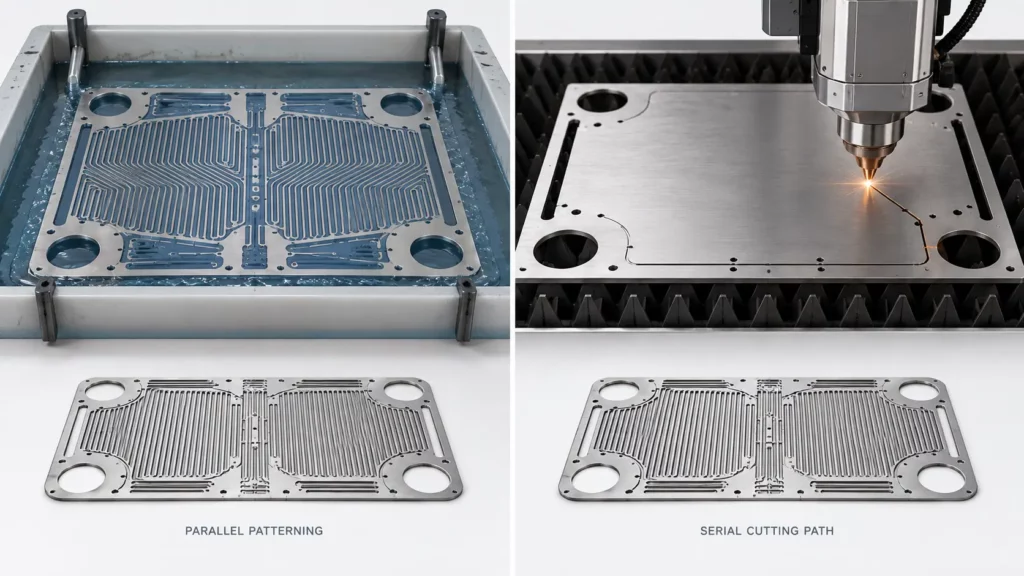
Both avoid hard stamping dies. Etching exposes many features in parallel; laser time generally grows with path length and pierce count.
Quick Process Comparison with Screening Values
| Decision factor | Chemical etching | Laser cutting | |
|---|---|---|---|
| Best-fit geometry | Dense channels, fine holes, manifolds and complex thin-sheet patterns | Perimeters, large ports, simple slots and thicker plate | |
| Feature depth | Partial-depth and through-etched features | Mainly through-cuts; blind features require ablation | |
| General thickness context | TMNetch lists 0.02–1.5 mm in its photo-etching guidance | ISO 9013:2017 covers evaluated laser-cut surfaces from 0.5–32 mm | |
| Minimum etched hole | Scales with stock thickness | Depends on kerf, pierce behavior and system | |
| Preliminary tolerance | Often screened as a percentage of thickness | Depends on machine, material, thickness and cut-quality class | |
| Main edge concern | Undercut, taper and rounded profile | Burr, dross, striation, oxide, taper and HAZ | |
| Commercial pattern | Strong when complexity repeats across a panel | Strong when geometry is simple and cutting paths are short |
These are DFM starting points. Confirm them against the alloy, pattern, panel and inspection plan.
Microchannel Heat Exchanger Fabrication Starts with Feature Depth
The first drawing question is simple: does the feature stop inside the plate, or pass through it?
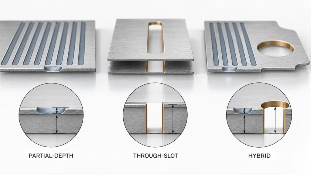
Partial-Depth Channels
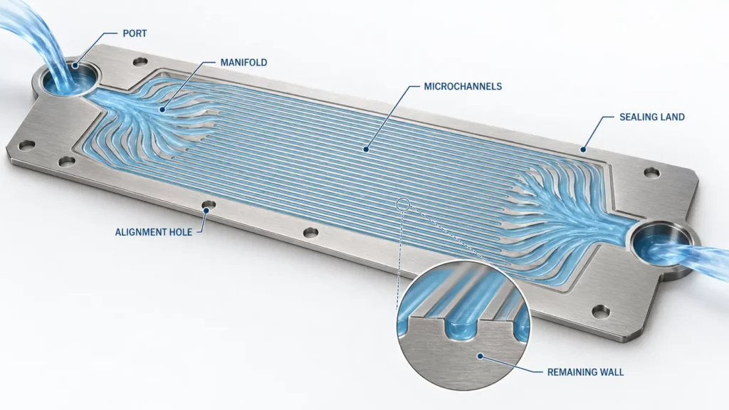
Many printed circuit heat exchanger plates use open channels recessed into one face. Alignment and joining turn those recesses into sealed passages. An Oak Ridge National Laboratory study describes photochemical machining and diffusion bonding in PCHE fabrication for Alloy 617.
Etching can place channels, a flow distribution manifold, ports and alignment features in one artwork. Drawings should state top width, bottom width, depth and remaining wall.
Conventional laser cutting cannot leave a controlled wall beneath a channel. Laser ablation can, but capability is process-specific. One 316L experiment produced a 43.39 μm-deep, 64.49 μm-wide channel with Ra of 0.37 μm. This laser micromachining example is not a supplier limit.
Through-Slots, Ports and Outer Profiles
Through-cut spacer layers can form passages between adjacent plates. Large ports, simple perimeters and thick covers are often efficient laser-cut features.
Etching can make through-openings in thin sheet. As stock thickens, etch time and lateral removal increase, making small openings harder to control.
Photochemical Machining Tolerances, Undercut and Minimum Features
Thickness Sets the Starting Scale
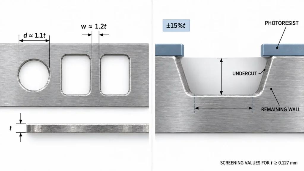
Minimum holes, slots and webs scale with sheet thickness. One PCM guide gives these starting values for stock at or above 0.127 mm:
- Minimum hole: about 1.1 × material thickness
- Dense-pattern web: about 1.2 × material thickness
- Initial dimensional tolerance: about ±15% of material thickness
Ratios become more conservative as stock thickens. Treat them as screening values; see the published PCM design guide.
What Undercut Means in Plain Terms
Etchant removes metal downward and sideways beneath the resist. The surface opening becomes slightly wider than the channel bottom, like a shallow trapezoid with softened corners.
That profile affects flow area, ligament width and joining land. Separate opening width, bottom width, depth and remaining wall on the RFQ.
Keep Tolerance Types Separate
Thickness, channel depth, hole size, position, flatness and registration require different measurement methods. A ±0.03 mm profile tolerance should not automatically apply to flatness or depth.
Laser Cutting Burr and Edge Quality in 316L Plates
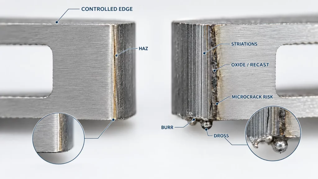
Laser cutting creates a localized heat-affected zone whose effect depends on alloy, thickness, speed, focus and assist gas. TWI explains the heat-affected zone and reports a trial with dross-free edges in 3 mm stainless steel.
Clean laser edges are achievable but must be specified. A 2025 AISI 316L study reported minimum burrs near 3 μm for CO₂-laser samples and 18 μm for fiber-laser samples; minimum Ra values were 1.11 and 1.06 μm. These are test-specific 316L results.
Edge condition matters beyond appearance. Dross and irregular relief can act as stress raisers under cyclic loading. Pressure-cycled plates may require checks for burr, oxide, recast material, roughness and microcrack risk. See the fatigue study.
Cost by Quantity: No Universal Break-Even Point
For a low-volume plate with a simple perimeter and few openings, laser often has lower entry cost because it needs no phototool. That advantage can disappear with thousands of channels or pierces.
Etching has phototool and setup costs. Panelized repeat production spreads those costs across more parts while processing many features at once.
Do not use “fewer than 50 parts” as a universal cutoff. Area, pattern density, depth, cutting length, yield and inspection can move the break-even point.
Use this cost model:
Total plate-system cost = setup + patterning + material loss + finishing + cleaning + inspection + scrap + joining preparation + joining risk + validation
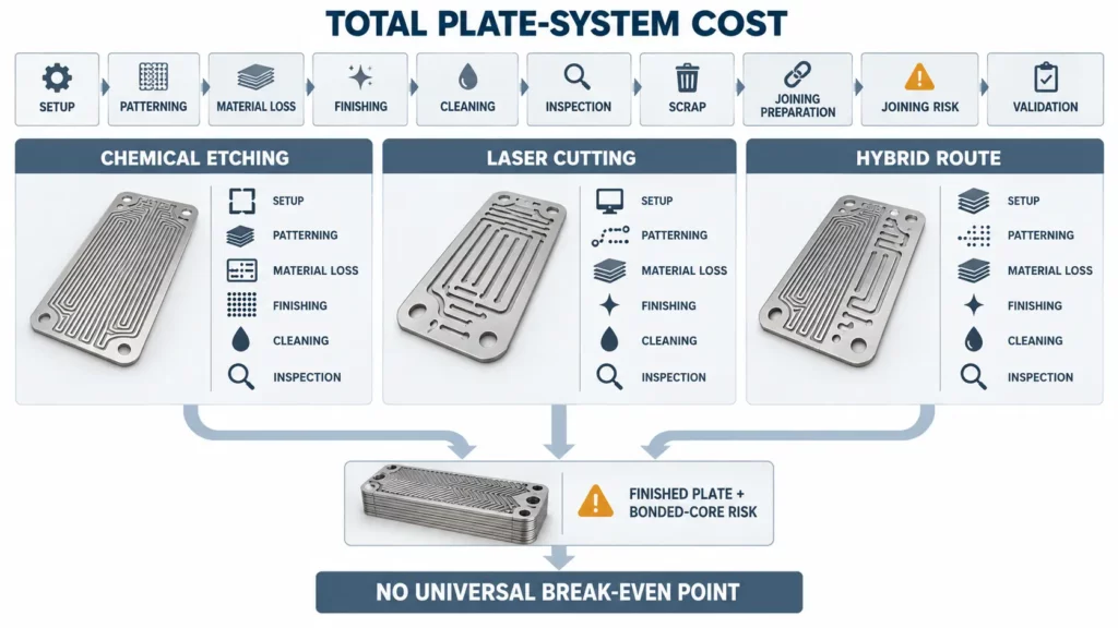
A Journal of Cleaner Production comparison evaluated six routes for one microchannel heat-recovery unit. Laser cutting with diffusion brazing had the lowest modeled cost; PCM with laser welding had the lowest modeled environmental impact. Joining can reverse a cutting-price conclusion.
Joining and Pressure-Rated Heat Exchanger Qualification
Patterned plates become a core only after alignment and joining. Diffusion bonding, brazing or welding adds requirements for flatness, cleanliness, roughness, oxide control and registration.
Research on zigzag PCHE passages found that diffusion bonding could narrow and shallow channels, changing predicted performance. Distinguish etched from final bonded geometry. Read the study.
Neither process alone determines pressure rating. Material strength, remaining wall, joints, headers, inspection and proof testing govern the system. Cutting-related edge quality, residual stress and surface condition can still affect joining and fatigue.
Case Snapshot: A Hybrid TMNetch Flow-Plate Project
| Project item | Recorded information |
|---|---|
| Component family | Large patterned flow plates |
| Manufacturing route | Chemical etching plus laser cutting |
| Most-used materials | 316 stainless steel and titanium |
| Largest recorded format | 600 × 1,400 mm |
| Stock envelope in the project record | Up to 4 mm |
| Main engineering lesson | Assign fine flow features and large structural cuts to the process suited to each |
The 4 mm figure is a stock envelope, not a claim that every 4 mm feature can be etched through. The record demonstrates a hybrid workflow; it does not establish pressure qualification.
Where Heat Exchanger Baffle Plates Fit
A thin, densely perforated baffle may suit etching; a thicker baffle with large holes may suit laser. Load-bearing supports, formed helical baffles and impingement plates require stiffness and vibration review.
In a shell-and-tube exchanger, a baffle is a flow-and-support component rather than a microchannel plate. See heat exchanger baffle plate design.
A Five-Step Selection Method
- Classify the part. Is it a channel plate, spacer, cover, manifold, distributor, baffle or structural support?
- Separate feature depths. Mark partial-depth recesses and through-features independently.
- Compare thickness with minimum geometry. Review holes, slots, webs, sealing lands and finished cross-sections.
- Add the joining and inspection requirements. Define flatness, surface condition, registration and post-joining dimensions.
- Quote complete routes. Compare setup, processing, finishing, cleaning, yield, inspection and joining risk.
For deeper design work, see photochemical etching for microchannel heat exchangers and photochemical etching tolerances.
RFQ Checklist
- Exact alloy, temper and certificate requirements
- Plate thickness, overall size and quantities by development stage
- Separate drawings for partial-depth and through-features
- Channel top width, bottom width, depth, pitch and remaining wall
- Minimum web and sealing-land width
- Port, perimeter and alignment-hole geometry
- Profile, position, depth, flatness and registration tolerances
- Acceptable burr, dross, oxide, undercut and residue conditions
- Intended diffusion bonding, brazing or welding route
- Working fluids, temperature, pressure and cycling context
- Inspection method, sampling plan and required reports
Frequently Asked Questions
Is chemical etching better than laser cutting for heat exchanger plates?
It usually fits thin plates with dense or partial-depth features. Laser fits thicker material and simple through-cuts. Mixed features may justify both.
Can laser cutting make microchannels?
Conventional cutting makes through-slots. Laser micromachining can make recesses, but depth, taper and roughness depend on the laser, material and scan strategy.
Does laser cutting always leave burrs or serious heat damage?
No. Optimized systems can produce clean edges. Critical plates should still define limits for burr, dross, oxide, roughness and thermal effects.
Which process is cheaper for prototypes?
Laser often favors a simple one-off profile because it needs no phototool. Etching may remain competitive for a dense prototype. Quote both routes instead of using a fixed threshold.
Can both processes be used on one plate?
Yes. Etching can form channels; laser can create large ports or the perimeter. Process order and cleaning must support joining.
Conclusion
Etching is strongest for thin, complex and densely patterned plates. Laser cutting is strongest for thicker stock and simple through-geometry. Hybrid manufacturing fits designs containing both.
The choice should protect channel geometry, joining surfaces and inspection requirements. To compare routes, submit your heat exchanger plate drawing with alloy, thickness, feature depths, tolerances, joining method and volume.