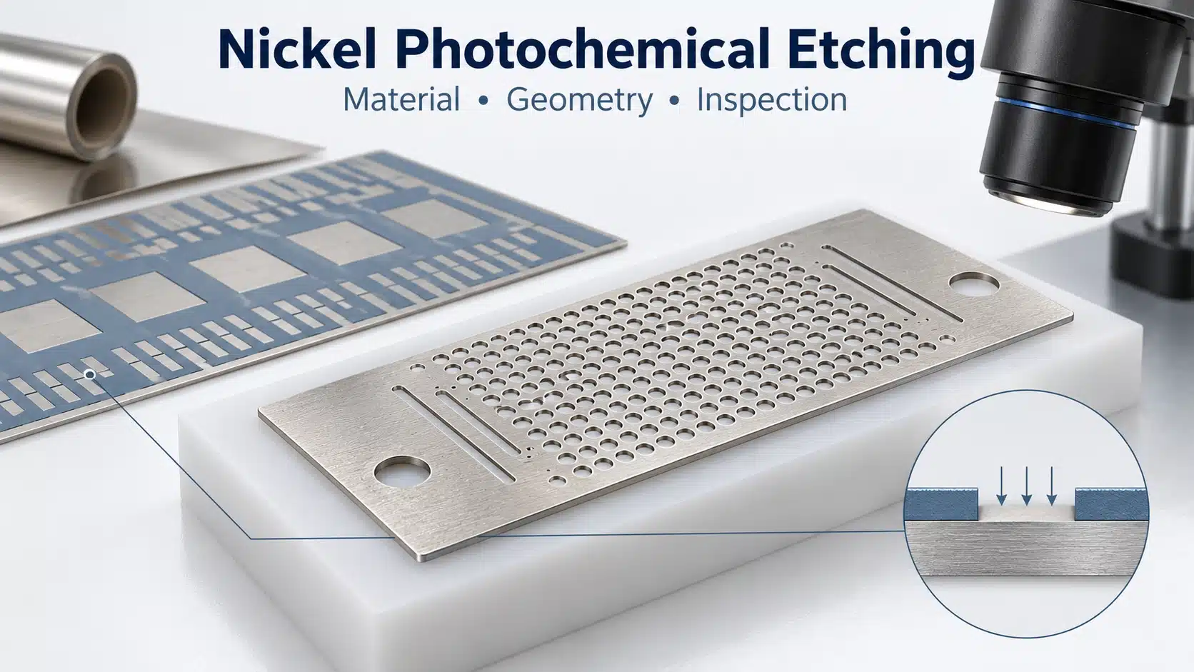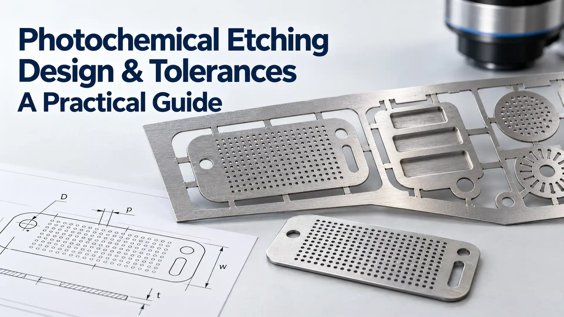

Photochemical etching removes selected metal through a protective, light-defined resist pattern. It is used to make detailed sheet-metal parts, but the drawing must connect the required geometry to measurable acceptance criteria. Start a design review with the material, thickness, critical features and finished condition.
This guide covers process basics, material inputs, tolerances and inspection requirements. For an active project, our chemical etching services provide a starting point for discussing your component.
Key Takeaways
- Specify the exact alloy, material condition and thickness.
- Identify dimensions that control fit or function.
- Review holes, slots, remaining metal and depth together.
- Agree how the finished component will be measured.
What Is Photochemical Etching?
Photochemical etching uses photoresist, a light-sensitive coating, to protect selected metal. An etchant, a chemical solution, removes the exposed areas. Photo etching, photochemical machining and photo chemical milling are related names used in the industry.
The method mainly serves sheet and foil components. Our chemical etching introduction explains the broader terminology and types.
How Does the Photochemical Etching Process Work?
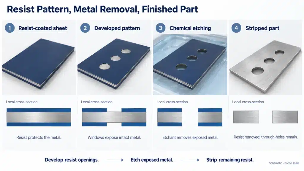
A practical photochemical etching sequence links drawing approval to the delivered part:
- Drawing and material review: Confirm the revision, alloy, thickness, geometry and required finish. Identify critical features during design for manufacturability, or DFM, review.
- Surface preparation: Clean the metal so the protective coating can adhere properly.
- Photoresist application: Apply the coating to the required surfaces.
- Imaging and developing: Use ultraviolet, or UV, exposure to form the image, then develop the resist to create openings. The areas removed during developing depend on the resist type.
- Chemical etching: Remove exposed metal through the developed pattern.
- Stripping and cleaning: Remove the remaining resist and clean the workpiece.
- Inspection and secondary operations: Check the required features, complete specified finishing, and inspect the agreed delivery condition.
These are broad stages. For production controls, cleaning arrangements and checks between operations, read our detailed chemical etching process guide.
When Photochemical Etching Fits the Design
Photo-defined tooling supports intricate patterns and prototype development. Consider the method when a thin part combines repeated openings, detailed outlines or a design that still needs revision.
Before selecting it, separate the required output into three questions:
- Is the part primarily a sheet-metal pattern?
- Which features require controlled depth or later forming?
- What must the sample demonstrate before production approval?
Compare manufacturing routes using the same material, geometry and delivered condition.
What Materials Can Be Photochemically Etched?
The material name alone is an incomplete specification. Use the following material inputs for review; detailed alloy information belongs in the photochemical etching materials guide.
Stainless Steel and Nickel Alloys
State the exact grade, thickness and supplied condition. Add surface and finishing requirements. For an Inconel grade or another nickel alloy, confirm capability for that specific material and drawing.
Copper Alloys: Phosphor Bronze, Brass and Beryllium Copper
Specify the alloy designation and temper, meaning its supplied material condition. Phosphor bronze properties vary with temper, so a generic material name does not fully define the starting stock.
For contacts or spring features, identify the required material condition before discussing geometry, forming and plating. Apply the same discipline to brass and beryllium copper.
Aluminum and Titanium
Include the grade, thickness, starting surface and intended finish. Ask the supplier to evaluate those inputs with the smallest openings and most important dimensions.
Molybdenum and Other Specialty Metals
For molybdenum, tungsten or a Co-Cr alloy, request a material-specific review. Confirm stock form, process suitability and acceptance requirements before assigning feature limits. A broad materials list should not replace approval of the actual job.
Photochemical Etching Tolerances and Design Guidelines
Achievable dimensions and tolerances depend on material, thickness and pattern design. Turn that relationship into explicit drawing requirements rather than applying one capability number to every feature.
Critical Dimensions and Tolerance Allocation
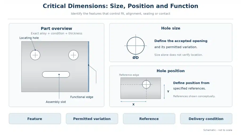
Identify features that control assembly, sealing, alignment or another required function. Give those features suitable dimensions and references; review less critical geometry separately.
Use a four-part check for each critical requirement: identify the feature, state its permitted variation, define its reference or measurement location, and specify the delivery condition. For a locating hole, review both its size and its position.
Material Thickness
Specify starting thickness and its permitted variation. Clarify whether a thickness requirement refers to supplied stock or the finished component.
Review it with the openings, remaining metal and recessed features. Avoid approving an opening from its diameter alone while leaving the sheet thickness unspecified.
Hole and Slot Size
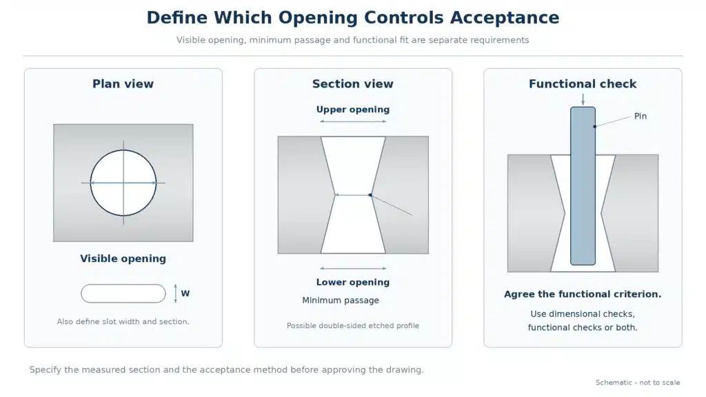
Define size, shape, location and pattern arrangement. Where the edge profile affects acceptance, identify the measurement location and whether the requirement concerns the visible opening, a minimum passage or a functional fit.
Ask the supplier to propose a method that can verify that requirement. A single undefined “hole diameter” may leave the measurement task unclear.
If a hole must accept a pin, agree whether acceptance will use dimensional measurement, a functional check or both. Record the chosen criterion with the drawing so sample and production reviews use the same requirement.
Web Width and Feature Spacing
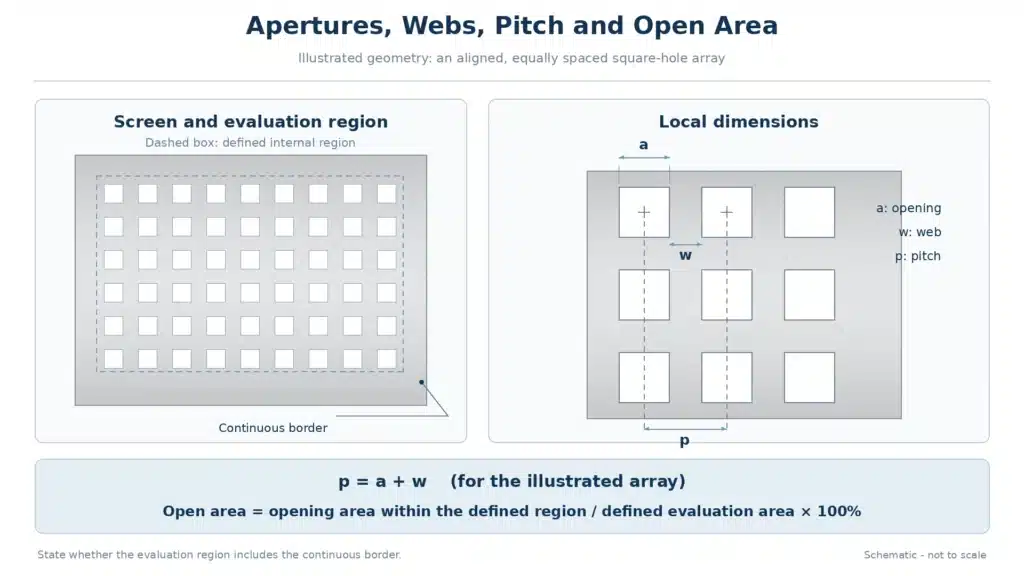
Show both the remaining metal between openings, or web width, and the center-to-center repeat spacing, or pitch. Dimension these separately on the drawing.
For a dense array, identify the narrowest remaining sections, border requirements and functional pattern. If open area matters, define the region over which it is evaluated.
Mark borders that must remain continuous. Agree whether inspection will cover individual openings, selected locations across the array or a separately defined pattern requirement.
Edge Profiles, Corners and Artwork Compensation
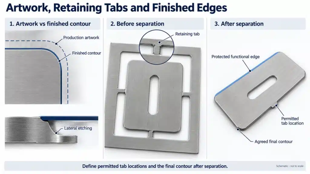
Lateral etching beneath the resist affects walls and corners. State the required finished contour and mark edges where projections, recesses or corner rounding could affect function.
For applicable drawings, ISO 13715 supports the indication of undefined edges. Agree the permitted condition for the actual part. Keep finished-part requirements distinct from the supplier’s compensated production artwork.
Part Size, Flatness and Surface Requirements
Define length and width separately from flatness and surface acceptance. Geometrical specifications distinguish form, orientation and location.
For a flexible part, agree its support condition during measurement. Identify relevant cosmetic areas, cleanliness requirements and the state in which the part will be accepted.
TMNetch Case: Defining Where a Connection Point Is Acceptable
In a TMNetch retaining-tab project, a customer asked whether small connection points around the parts were production defects.
The factory explained that these were intentional connections. Their size could be reduced where design and processing conditions allowed. The customer accepted them provided they did not affect the finished part’s functional area.
For similar parts, mark permitted tab locations and identify functional edges that must remain clear. Agree the acceptable contour after separation. The customer’s condition becomes useful for production when it is expressed as a location, geometry or inspection requirement.
How to Specify Half-Etched and Multi-Depth Features
Depth, Remaining Thickness and Front-to-Back Features
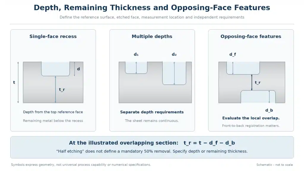
Partial-depth etching leaves metal beneath the recessed area. For half-etched or multi-depth features, identify the etched face, required depth or remaining thickness, allowed variation and measurement location.
Show their relationship to nearby through-features and opposite-face details. Check that related thickness and depth dimensions do not conflict. Agree how the specified condition will be measured before approving artwork.
Where both depth and remaining thickness appear, review their relationship to the starting stock. Identify which dimensions are independent requirements and which are derived references, using the drawing convention agreed for the project.
Folded Model Parts vs. Multi-Depth Etching
A three-dimensional model assembled from flat pieces differs from depth features within a sheet. Folding along etched lines is a subsequent forming operation.
For model parts, define folds, slots and assembly interfaces. For recessed structures, define depth and remaining metal. Use the intended result to clarify what “3D photo chemical etching” means in the enquiry.
Design Checks for Common Photo-Etched Parts
Use this proposed review checklist to connect each component to its drawing requirements.
| Component | Requirements to confirm |
|---|---|
| Filters and screens | Apertures, pitch, webs, border, flatness and cleaning |
| Bipolar plates | Channel dimensions, face orientation, remaining thickness and finished interfaces |
| Speaker grilles | Opening pattern, cosmetic zones, coating and assembly |
| Vapor chamber components | Internal features, joining areas and cleanliness |
| Nameplates and signs | Lettering, recesses and appearance after finishing |
| Folded model parts | Fold lines, interlocking features and tab locations |
| EMI/RFI shields | Profile, bends, contact areas and plating |
| Lead frames and contacts | Pitch, conductor widths, material condition and finish |
| Shims and encoder discs | Thickness, profiles, hole or angular positions and flatness |
For custom etched filters or metal bipolar plates, identify the finished interface and required verification with the geometry.
Inspection Requirements for Drawing Approval
Measurement equipment selection must match the geometry, tolerances and measurement requirements. Agree the feature boundary, access, setup and method before choosing an instrument.
Document four items:
- What: The characteristic and drawing requirement being checked.
- Where: The face, section or measurement location.
- When: The manufacturing state, including required finishing.
- Record: Results, sampling arrangement and required documents.
Measurement uncertainty affects acceptance decisions. For tight requirements, agree how uncertainty enters the acceptance rule. Do not treat an instrument name as proof that a particular feature can be verified.
Ask for a report that connects results to drawing characteristics and revision. Include the agreed measurement locations and finished condition so the customer and supplier can review the same acceptance task.
Design Checks That Need a Feasibility Review
Request additional review for narrow deep recesses, critical wall profiles, very small remaining sections or demanding flatness requirements. Identify the function behind each requirement so the supplier can evaluate adjustments.
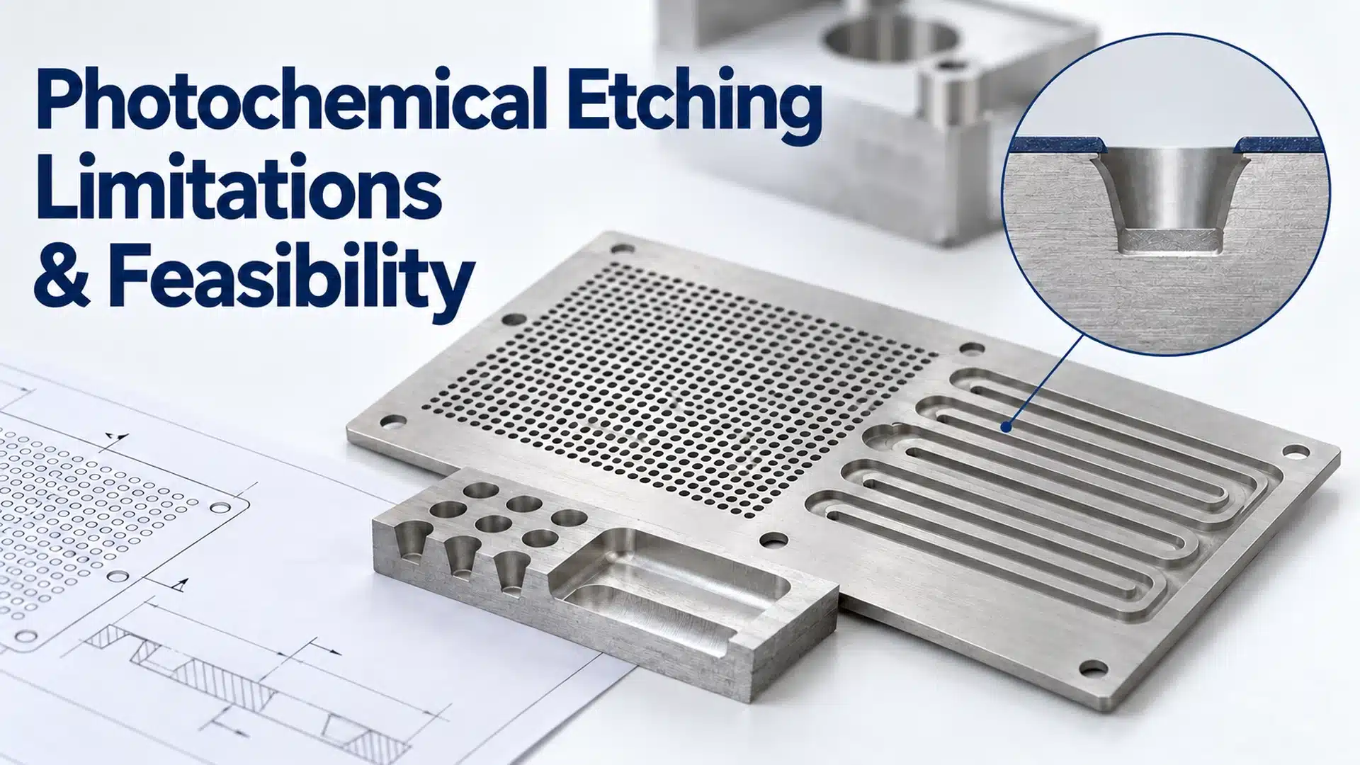
For complex solid geometry, assess whether a sheet-based process fits the task. Our guide to photochemical etching limitations explains the mechanisms and possible alternatives.
Prototype Validation and RFQ Checklist
What to Validate on the First Sample
Photochemical machining supports development from prototype to production. Define the sample’s purpose: dimensional verification, assembly, edge acceptance or another stated check.
Record the tested revision, material and finished condition. Review production approval against the evidence collected, including any changes made after sampling.
What to Send for a Design Review
Include the drawing or computer-aided design file, alloy, condition, thickness, quantity, critical dimensions, partial-depth features, finish and inspection requirements.
Define the quotation scope before comparing photochemical etching costs. Send these details to TMNetch for a design review and identify the requirements that affect function or assembly.
FAQs About Photochemical Etching Design
Can one tolerance be applied to every feature?
Review size, position, depth and form as separate requirements. Assign tolerances from the part’s function and confirm manufacturability and measurement capability for each critical feature.
What material details are needed for a tolerance review?
Provide the exact alloy, condition, thickness and starting surface. Include finishing requirements and identify whether acceptance applies before or after those operations.
Does half etching mean removing exactly half the thickness?
Do not rely on the name to define depth. Specify the required recess or remaining thickness, its tolerance and the location to be checked.
Should dimensions be checked before or after plating?
State the condition to which each requirement applies. Use intermediate checks where needed, and verify finished-part requirements after the relevant finishing operations.