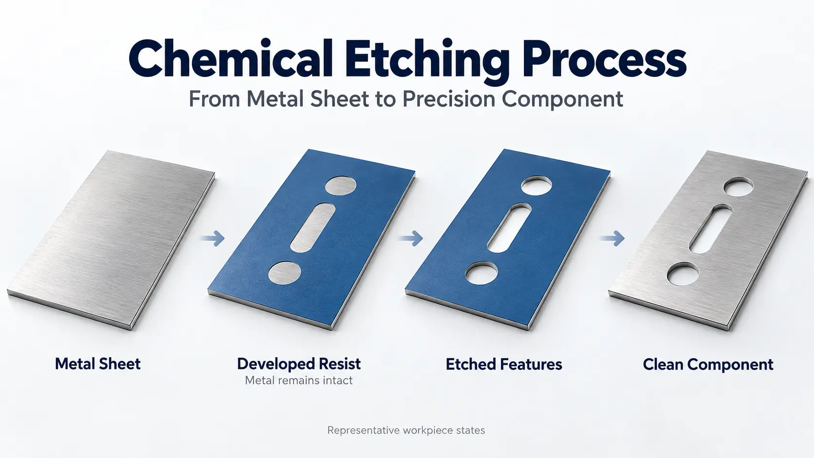

Quality inspection for etched heat exchanger components should verify material identity, finished geometry, surface condition and cleanliness against an approved drawing. After joining, the core needs separate checks for leakage, pressure resistance and flow performance. A dimensional report for an individual plate covers only one stage of that process.
For buyers sourcing precision chemical etching, the practical starting point is an inspection plan connecting each critical feature to a measurement method, acceptance limit and record. The following framework helps turn “high quality” into requirements that both supplier and customer can verify.
Start With the Part, the Drawing and the Inspection Stage
An etched flow plate, a bonded core and a completed exchanger require different evidence. Assign inspection responsibilities before production, especially when separate suppliers handle etching, joining and final assembly.
| Inspection stage | Main questions | Evidence to agree |
|---|---|---|
| Individual etched plate | Are material, channels, holes and surfaces correct? | Material records and dimensional, visual and cleanliness results |
| Bonded or brazed core | Are layers aligned, passages open and circuits separated? | Joining records, flow checks and specified leak tests |
| Completed exchanger | Does the assembled pressure boundary meet project requirements? | Applicable pressure, leak and functional test reports |

Material, Thickness and Traceability Checks
Begin with the specified alloy, material condition and thickness. Match the material certificate to the received stock and preserve its heat or lot identity through processing. Include any customer requirements for chemical composition, mechanical properties or supply condition.
Positive material identification can supplement these records, but the method must detect the relevant elements. In particular, X-ray fluorescence cannot measure carbon. An XRF result consistent with 316 stainless steel therefore cannot independently establish the low-carbon requirement of 316L.
Measure stock thickness at agreed locations, then distinguish it from channel depth and remaining wall thickness. Record the instrument, contact conditions and sheet support where they affect the result. Measurements intended to represent original stock thickness should use appropriate unetched areas.
Maintain measurement traceability as well as material traceability. Metrological traceability connects a measurement result to a reference through a documented calibration chain, with uncertainty considered along that chain. A calibration label alone does not demonstrate suitability for every feature.
Measuring Holes, Flow Channels and Remaining Walls
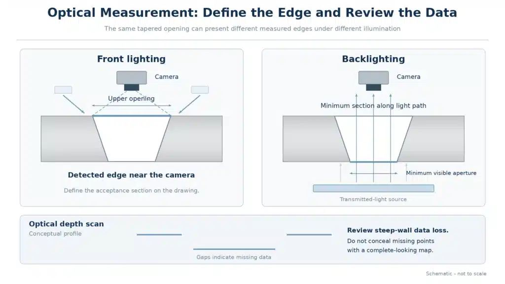
Define exactly what each dimension represents before selecting equipment. An etched opening can have different dimensions at its upper surface, lower surface and narrowest section. The drawing should identify the section that controls acceptance.
The following is a method-selection framework, rather than a claim that every instrument suits every plate. Vision measurement conditions and the drawing’s geometric requirements must guide the final setup.
| Feature | Candidate method | Detail to define |
|---|---|---|
| External profile and ports | Vision system, projector or suitable CMM | Datum alignment and measured edge |
| Tube holes and slots | Vision measurement or suitable probing | Opening section, diameter and position |
| Blind-channel depth | Validated 3D profiling or section measurement | Reference surface and accessible geometry |
| Narrow lands and webs | Suitable optical or sectional measurement | Location of the minimum required material |
| Double-sided patterns | Registered measurements of both faces | Common reference and overlap location |
Lighting is especially important for tapered openings. Backlighting reveals the minimum opening along the transmitted light path, while front lighting can reveal the opening nearest the camera. Record the illumination and edge-detection settings when they influence acceptance.
Optical depth measurements also need a suitability check. In coherence scanning interferometry, steep slopes and other optical limitations can produce missing surface data. Review the measured region and missing points before accepting a channel profile; a complete-looking colour map is insufficient evidence.
For a baffle plate, checking tube-hole diameter alone leaves the hole pattern unverified. Assess location against the specified datums and geometric tolerances, using the drawing’s chosen system, such as ASME Y14.5.
Illustrative remaining-wall calculation: Consider a 0.500 ± 0.010 mm plate with overlapping channels etched 0.150 ± 0.015 mm from each side. The nominal wall is 0.200 mm. Combining the minimum stock thickness with both maximum depths gives:
Minimum calculated wall = 0.490 − 0.165 − 0.165 = 0.160 mm
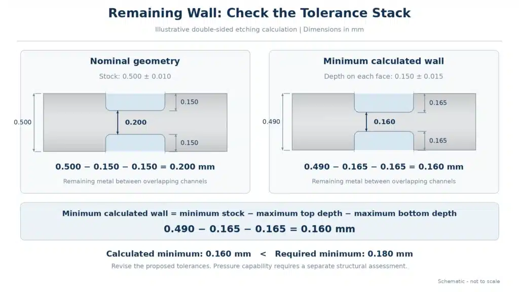
If the design requires 0.180 mm, the proposed tolerances need revision. This hypothetical calculation checks a geometric tolerance stack before joining; pressure capability needs a separate structural assessment.
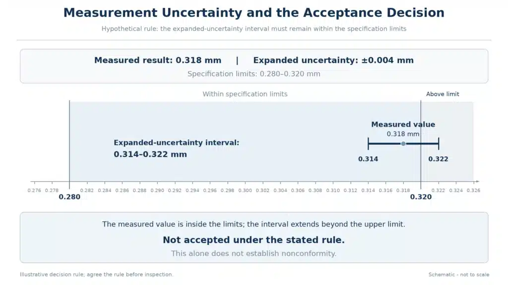
Near a dimensional limit, agree how measurement uncertainty affects acceptance. Conformity decision rules address this issue. A result just inside a tolerance should be evaluated using the agreed rule, rather than rounded into a pass.
For a hypothetical guard-band decision, suppose acceptance requires the expanded-uncertainty interval to remain within the limits. A 0.318 mm result with expanded uncertainty of ±0.004 mm spans 0.314–0.322 mm. Against limits of 0.280–0.320 mm, it would not qualify for acceptance under that rule. This alone does not establish nonconformity.
Flatness, Edge Quality and Surface Condition
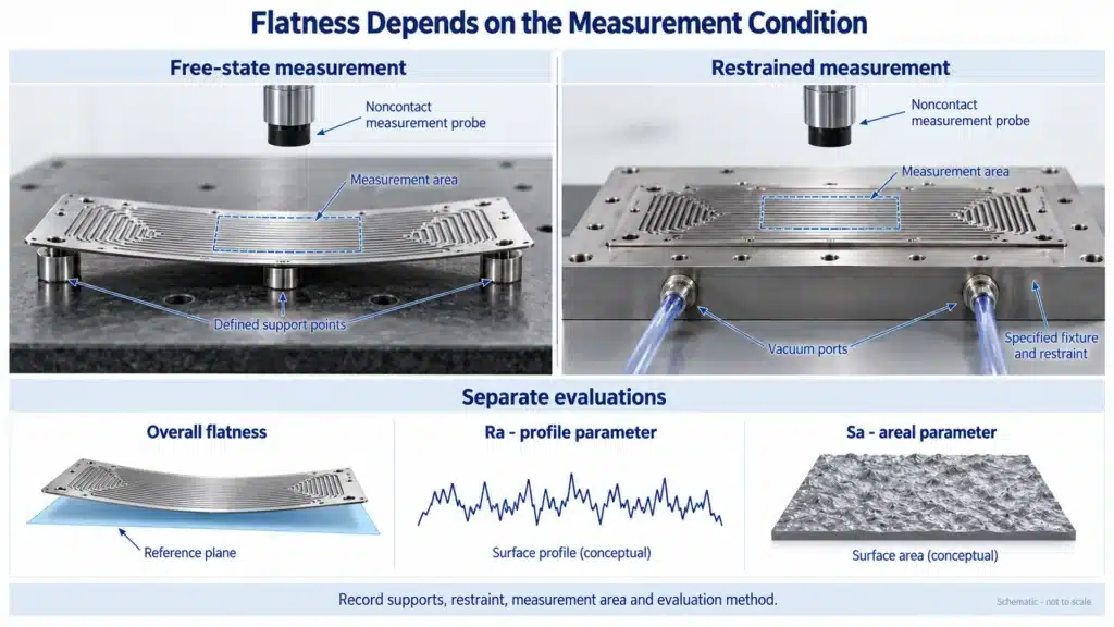
Specify whether flatness applies to the free plate or to a restrained condition. For thin, flexible components, non-rigid-part dimensioning allows verification conditions to be defined. Record supports, restraint or vacuum conditions, measurement area and evaluation method. Otherwise, two inspectors may be measuring different conditions.
Keep overall flatness separate from surface texture and local damage. A scratch, pit or damaged sealing land needs its own acceptance criterion. For diffusion bonding, surface roughness and flatness affect contact at the joining interface, so obtain requirements from the joining process owner before approving the plates.
Specify the texture parameter as well as its limit. Profile parameters such as Ra and areal parameters such as Sa describe different evaluations. Agree the measurement location, filtering and evaluation extent instead of requesting an undefined “smooth surface.”
TMNetch Case: A Customer Question About Retaining Tabs
In a previous TMNetch etching order, a customer questioned small connection points around the parts. These were intentional retaining tabs. The factory explained their purpose and that their size could be reduced where processing conditions allowed. The customer accepted them provided they did not affect the finished part’s functional area.
This retaining-tab case concerned a general etched-part order, rather than a documented heat exchanger project. Its inspection lesson is directly useful: distinguish the connection before separation from the edge condition afterward.
For a heat exchanger component, translate that lesson into approved tab locations, protected functional areas and permitted final projections or recesses. These are recommended controls for future orders, rather than reported measurements from the original case.
Cleanliness Before Joining and Shipment
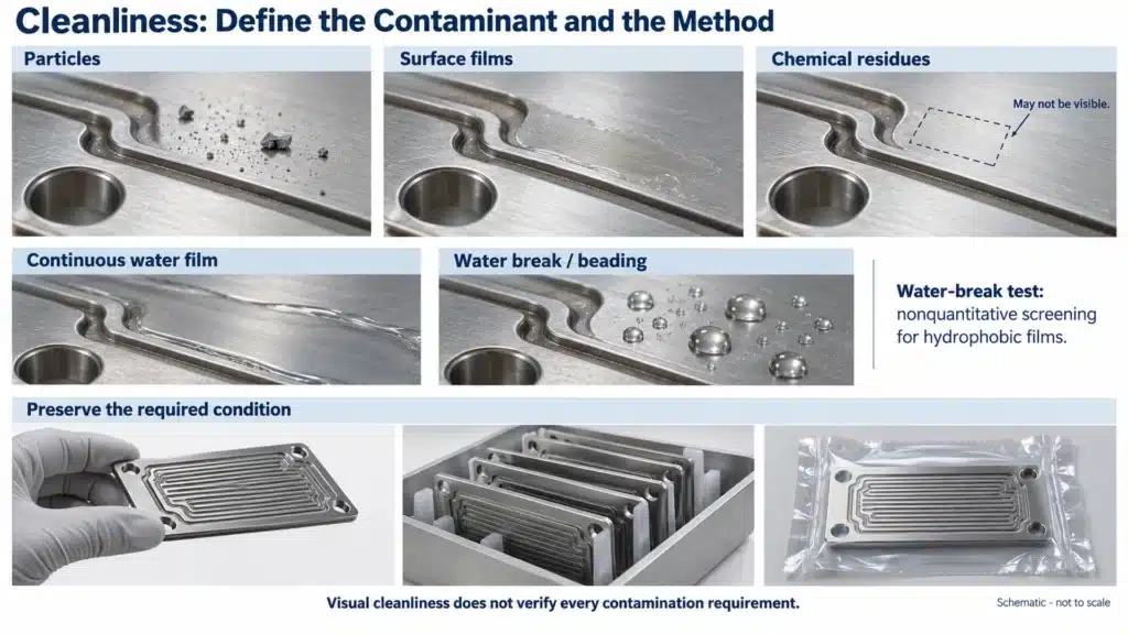
Divide cleanliness requirements into particles, surface films and chemical residues. Specify the contaminant of concern, test method, inspected area and acceptance limit. A visually clean plate does not establish compliance with every cleanliness requirement.
For particulate inspection, ISO 16232 provides methods developed for road-vehicle components. Its scope does not cover all contamination types or establish universal limits for heat exchanger plates. Where its methods are adopted, agree their suitability and the project-specific particle criteria.
A water-break test screens for hydrophobic surface films. It is nonquantitative and does not demonstrate the absence of every ionic or chemical residue.
Include handling and packaging in the cleanliness plan. Define approved gloves, contact materials, separation between plates and protection after cleaning. If cleanliness is required at the joining stage, agree how it will be maintained or re-established before assembly.
Leak and Pressure Testing After Core Assembly
A loose plate normally lacks the completed exchanger’s enclosed pressure boundary. Purpose-built fixtures may test selected features, but the fixture and procedure must represent the question being investigated.
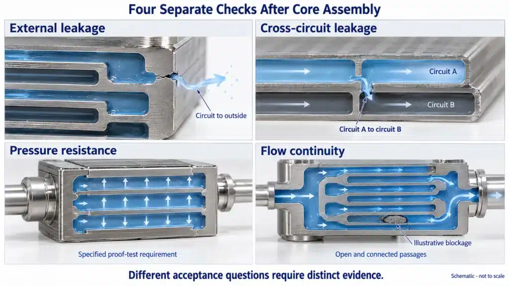
Separate four acceptance questions:
- External leakage: Can fluid escape from the assembled circuit?
- Cross-circuit leakage: Can fluid pass between circuits that should remain isolated?
- Pressure resistance: Does the assembly satisfy the specified proof-test requirements?
- Flow continuity: Are passages open and connected as designed?
Tracer-gas leak testing provides methods for locating or measuring leakage. Specify the tracer gas, test configuration, pressure conditions, instrument capability and acceptance threshold. The method reference alone does not supply a universal allowable leak rate.
Set pressure-test conditions through the applicable equipment specification and responsible designer. Record the tested assembly’s identity and condition. If later operations alter its pressure boundary, determine which acceptance checks must be repeated.
Sampling Plans and Inspection Coverage
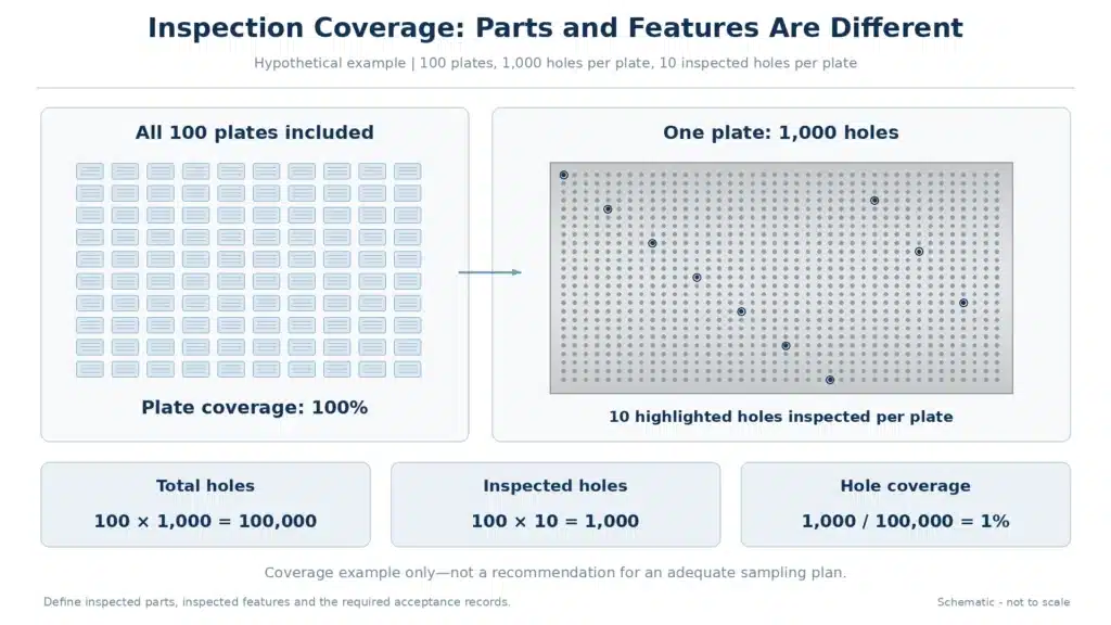
Define both the number of inspected parts and the number of inspected features. “100% inspection” is incomplete unless the report identifies what was checked.
For example, inspecting ten holes on each of 100 plates, with 1,000 holes per plate, covers every plate but only 1% of the holes. This hypothetical example describes coverage; it does not establish whether that coverage is adequate.
For lot acceptance by attributes, ISO 2859-1:2026 provides AQL-indexed sampling schemes. Specify the applicable edition, lot definition, inspection unit, defect classifications, inspection level and acceptance or rejection criteria.
An AQL-based plan balances producer and customer risks; acceptance sampling does not guarantee a defect-free lot. Select coverage for critical walls, sealing features and locating holes according to their consequences of failure.
Also distinguish first-article inspection from routine production checks. Establish when drawing revisions, material changes or process changes require renewed verification. Keep the trigger and required evidence in the agreed inspection plan.
What a Useful Inspection Report Should Include
A useful report lets the customer connect each result to the correct part, requirement and measurement conditions. Measurement data reporting provides a structured basis for communicating dimensional results.
For an etched heat exchanger component, request:
- Part number, drawing revision, production lot and material identification;
- Numbered characteristics linked to the drawing;
- Nominal values, tolerance limits, units and actual results;
- Measurement method, relevant setup and instrument identification;
- Sampling coverage and the acceptance decision;
- Uncertainty information where needed for the decision rule;
- Nonconformances, approved dispositions and inspection authorization.
Make disagreement handling part of the plan. If a result fails or remains inconclusive, identify the affected material and agree additional measurement, rework or customer disposition before release. Retain the original result alongside any subsequent inspection. An accepted concession should identify its scope rather than silently changing the drawing requirement.
TMNetch’s chemical-etching process includes CMM dimensional control and visual inspection. The titanium etching service also lists 2D vision inspection, first-article inspection (FAI) and outgoing quality control (OQC) reports. Agree the required records for the specific material and project.
A quality-management certificate supports supplier-system evaluation. Product acceptance still requires evidence against the order’s requirements. Before production, send TMNetch the component drawing and inspection requirements, including critical dimensions, joining conditions, sampling expectations and required report formats.
Frequently Asked Questions
Can a 2D image verify channel depth?
It can verify visible planar features under suitable conditions. Depth requires an appropriate validated measurement method, rather than an assumption based on image appearance.
Does a flatness result need a fixture description?
Yes, where support or restraint affects the result. Identify the specified measurement condition so that supplier and customer can reproduce it.
Does first-article approval cover every production part?
It verifies the inspected first article and agreed characteristics. Production acceptance requires its own defined inspection coverage and records.
Can a bare plate’s dimensional report prove pressure capability?
No. Dimensional results support design verification, while the assembled core and completed exchanger require their specified structural assessment and acceptance tests.
Conclusion
Quality inspection for etched heat exchanger components should be built around the function of each feature and the stage at which it can actually be verified. For an individual etched plate, the priority is confirming material identity, thickness, channel and hole geometry, remaining wall thickness, flatness, surface condition and cleanliness. After plates are bonded or brazed into a core, inspection must shift toward layer alignment, passage continuity, cross-circuit leakage and joining integrity. Final pressure and functional performance belong to the completed exchanger rather than the loose etched plate.
The most reliable approach is therefore not simply to request “100% inspection,” but to define an inspection plan that links every critical characteristic to a drawing requirement, measurement method, sampling level, acceptance limit and traceable record. Measurement uncertainty, fixture conditions and decision rules should also be agreed where they can affect conformity decisions.
For buyers, this means inspection requirements should be established before production begins. Providing the supplier with the latest drawing revision, critical dimensions, joining requirements, cleanliness expectations, sampling rules and required inspection reports makes quality measurable rather than subjective—and reduces the risk of discovering dimensional, cleanliness or assembly problems only after the heat exchanger core has been completed.