
An optical aperture may look simple on a drawing. It might consist of a circular hole, a narrow rectangular slit, or a window surrounded by several mounting features. But the finished component must do more than reproduce that two-dimensional pattern. It must provide the intended opening through the metal and maintain its position within the optical assembly.
This distinction matters when manufacturing photo-etched optical apertures. Photochemical etching can produce complex openings and external profiles in thin metal without relying on a mechanical cutting tool. However, material thickness, lateral etching, and the resulting edge profile influence the actual geometry of each opening.
Understanding these relationships helps engineers evaluate photochemical etching for custom metal apertures, precision optical slits, masks, and light shields used in spectroscopy, imaging, and analytical instruments.
Key Takeaways
- An optical aperture’s drawing dimension, surface opening, and unobstructed through-opening are not necessarily identical.
- Photochemical etching is worth considering for thin metal components with circular apertures, rectangular windows, custom profiles, and multiple openings.
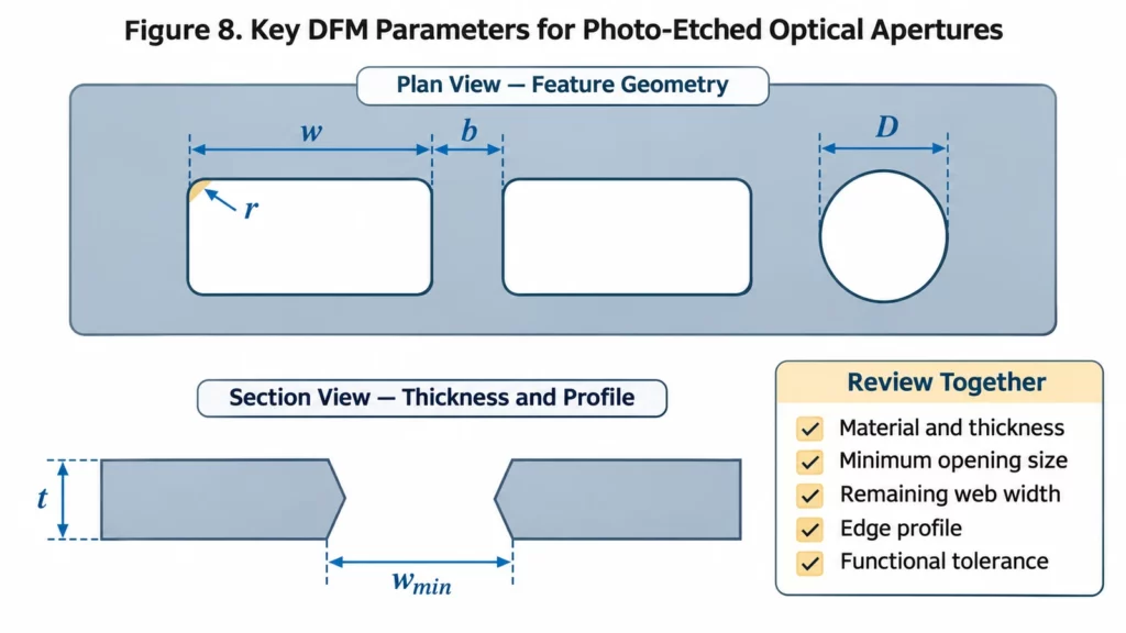
- Material thickness, opening size, edge profile, and remaining web width must be evaluated together.
- Optical openings and mechanical mounting features can be integrated into a single etched component.
- Extremely narrow slits or specialized edge requirements may require precision laser micromachining, electroforming, or another manufacturing process.
What Makes a Metal Aperture an Optical Component?
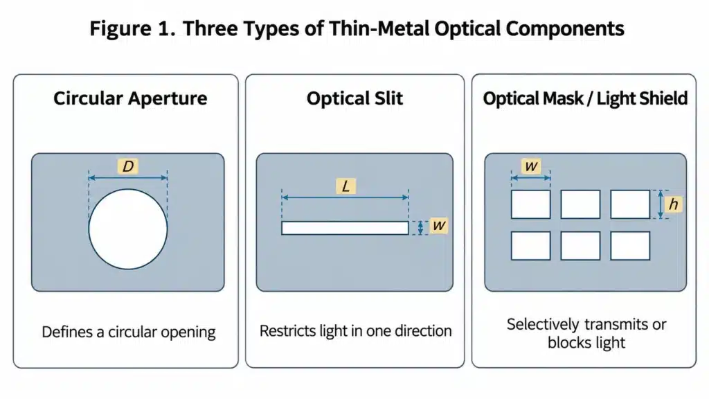
An optical aperture is an opening that allows or limits the passage of light. In precision instruments, its geometry helps define the region through which light can travel.
The required opening depends on the component’s function.
A circular aperture can define a geometric measurement area. A rectangular slit can restrict light in one direction. A patterned metal mask can expose selected regions while blocking others.
These structures serve different purposes, but they share a manufacturing requirement: the finished opening must correspond to the optical function assigned to it.
For example, radiometric and photometric measurements can require apertures with accurately known areas. In a spectrometer, the entrance slit participates in the trade-off between optical resolution and throughput.
Optical openings also appear in diagnostic instruments. The photometric system of the Roche cobas c 513 clinical chemistry analyzer, for instance, contains a mask and multiple slits along its optical path.
These examples illustrate why professional optical instruments require more than simply perforated metal. Each opening has a defined role within an assembly.
For a manufacturing engineer, the first question is therefore not just whether a hole can be etched. It is whether the finished metal opening can reproduce the geometry required by the optical design.
The Drawing Opening Is Not Always the Functional Optical Opening
A two-dimensional CAD drawing defines the nominal shape and dimensions of an aperture. The manufactured component, however, has thickness and an actual edge profile.
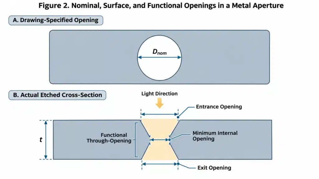
For thin metal optical components, it is useful to distinguish three types of opening.
Drawing-Specified Opening
The drawing-specified opening is the nominal geometry and associated tolerance defined by the customer.
For example, a drawing might specify a circular opening of Ø0.500 mm or a rectangular slit that is 0.100 mm wide.
These dimensions establish the manufacturing target. For a critical optical feature, the drawing should also make clear which physical boundary the dimension represents.
Surface Openings
The surface openings are the actual openings measured at the entrance and exit surfaces of the metal.
A manufactured aperture can have different entrance and exit dimensions, depending on its sidewall geometry and production process.
Even when both surface openings have the same diameter, the internal cross-section can contain a narrower region.
This is particularly relevant to photochemical machining because the etchant removes material both through the thickness and laterally beneath the protective resist.
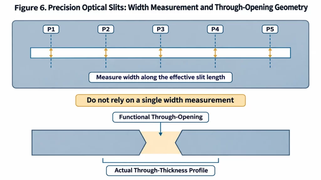
Functional Through-Opening
For this manufacturing discussion, the functional through-opening is the unobstructed geometric opening available along a specified light direction.
It depends on the complete aperture profile, not simply the dimension measured on one surface.
For a symmetric, concentric aperture under normal incidence, the smallest internal cross-section may define this opening. If the entrance and exit profiles are offset, however, the unobstructed region depends on the overlap of the opening boundaries throughout the metal thickness.
| Opening definition | What it represents | Why it matters |
|---|---|---|
| Drawing-specified opening | Nominal geometry and tolerance | Establishes the design requirement |
| Entrance surface opening | Actual opening at the first surface | Describes one boundary of the manufactured profile |
| Exit surface opening | Actual opening at the opposite surface | Identifies differences between the two surfaces |
| Functional through-opening | Unobstructed region along the specified direction | Connects manufactured geometry to the intended light path |
The distinction is important because measuring an entrance surface alone may not establish the actual geometric opening through the component.
A Circular Aperture Example
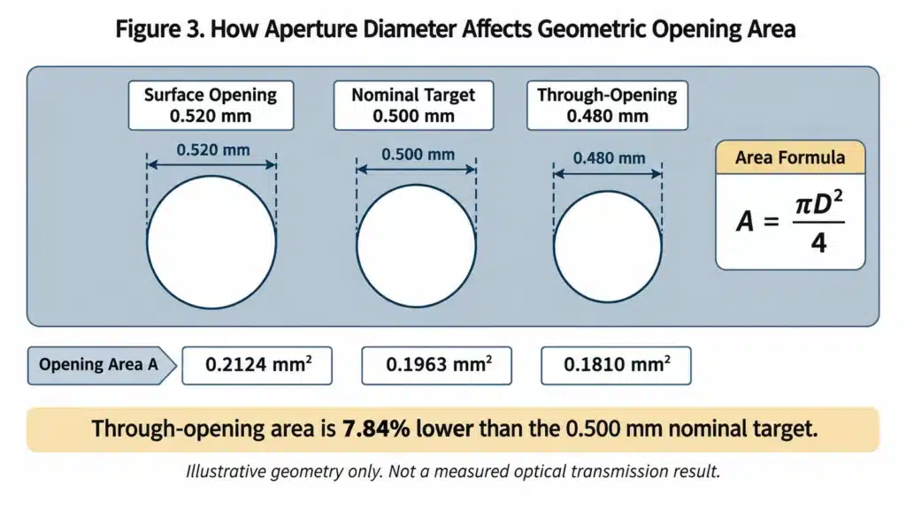
Consider a hypothetical circular aperture manufactured from 0.100 mm stainless steel.
The intended functional diameter is 0.500 mm. Assume that inspection identifies the following dimensions:
| Aperture feature | Diameter |
|---|---|
| Drawing target | 0.500 mm |
| Entrance surface opening | 0.520 mm |
| Exit surface opening | 0.520 mm |
| Smallest internal opening | 0.480 mm |
Assume that the aperture is concentric and symmetric, and that light travels perpendicular to the sheet.
Under these conditions, the 0.480 mm internal diameter limits the unobstructed opening.
The geometric area of a circular opening is:
A = πD² / 4
The three relevant areas are:
| Opening | Geometric area |
|---|---|
| 0.500 mm drawing target | 0.1963 mm² |
| 0.520 mm surface opening | 0.2124 mm² |
| 0.480 mm internal opening | 0.1810 mm² |
The smallest internal opening has approximately 7.84% less geometric area than the nominal 0.500 mm target.
This calculation does not predict the instrument’s actual optical throughput. It excludes diffraction, scattering, beam distribution, and other system-level effects.
It does, however, demonstrate why the measurement location matters. The surface opening is larger than the drawing target, while the internal opening is smaller.
For applications that require accurately known aperture areas, optical coordinate measurement of the aperture boundary provides a more rigorous approach than assuming that a nominal diameter represents the complete opening.
The manufacturing implication is straightforward: define the opening that performs the optical function before deciding how to manufacture and inspect it.
How Photochemical Etching Creates Optical Aperture Profiles
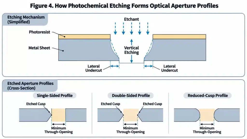
The geometry of a photo-etched aperture begins with a patterned protective layer on the metal.
In photochemical machining, a photoresist defines which regions of a metal sheet remain protected and which regions are exposed to the etchant. Chemical dissolution removes the exposed material, creating the desired openings and external profiles.
Unlike mechanical cutting, the process does not require a cutting tool to follow each aperture boundary. Multiple holes, slots, and profiles can be defined in the same phototool design.
This makes photochemical etching particularly useful when a thin component contains several geometric features.
Through-Thickness Etching and Lateral Material Removal
Etching removes metal in more than one direction.
As the etchant penetrates the exposed region, it also removes material laterally beneath the edge of the photoresist. This lateral removal is commonly called undercut.
Undercut influences the final opening dimensions and sidewall shape. The phototool dimensions therefore need to account for the expected material removal rather than simply reproduce the finished component dimensions.
During phototool development and engineering, material thickness, feature geometry, dimensional tolerances, and etch compensation are evaluated together.
For an optical aperture, this compensation should target the opening boundary specified by the customer.
If a particular internal opening controls the light path, compensating only for the surface dimensions may not address the actual functional requirement.
Single-Sided and Double-Sided Etching
The way material is removed from the sheet also influences the resulting aperture profile.
Single-sided etching removes material from one exposed surface. A through-etched opening produced this way can have a directional profile, with different dimensions at the two surfaces.
Double-sided etching removes material from opposing surfaces. Depending on the process conditions, the resulting opening can have a narrower internal region or a characteristic edge cusp where the etched profiles meet.
These profiles are not necessarily manufacturing defects. They are geometric characteristics that must be evaluated against the component’s requirements.
Different approaches to etched hole and edge profiles can produce conventional convex cross-sections, reduced-cusp profiles, and certain conical openings.
| Etched profile | Potential manufacturing characteristic | Optical design consideration |
|---|---|---|
| Single-sided profile | Directional opening through the sheet | Confirm entrance and exit orientation |
| Double-sided convex profile | Internal cusp or narrower region | Define and inspect the limiting through-opening |
| Reduced-cusp profile | Smaller internal edge projection | Evaluate whether the profile meets the required optical boundary |
| Controlled tapered profile | Different opening dimensions through thickness | Assess the specified light direction and edge geometry |
These are possible process configurations, not universal guarantees for every material or thickness.
A specialized profile must be established through supplier-specific engineering and sample verification.
The Advantage of Designing the Aperture Around Its Function
The ability to evaluate different etched profiles changes how engineers can approach an optical component.
Rather than treating the sidewall shape as an unavoidable consequence of manufacturing, they can identify whether a conventional etched edge is acceptable or whether a controlled profile is required.
For a simple light shield, the edge may only need to maintain a defined blocking boundary. For a precision slit, the internal profile and edge straightness may require greater control.
The appropriate level of process control depends on the optical task.
This is one reason photochemical etching deserves consideration in professional optical component manufacturing: it allows the planar opening pattern and the resulting through-thickness geometry to be evaluated as parts of the same design.
Which Optical Aperture Geometries Are Suitable for Photo Etching?
Photochemical etching is especially worth evaluating for optical components that can be manufactured from flat metal sheet or foil.
The suitability of a particular design depends on its smallest features, material thickness, required profile, and dimensional tolerances.
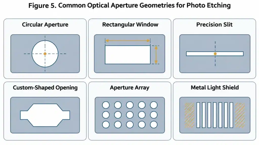
Circular Metal Apertures
Circular apertures are a natural starting point for photo etching because their geometry can be defined directly in a phototool.
Potential designs include fixed circular apertures, round openings in detector plates, and apertures surrounded by mechanical mounting features.
For these components, the engineering review should establish:
- The required functional diameter.
- The acceptable opening profile and roundness.
- The position of the aperture relative to the mounting references.
Accurately defined circular openings are used in applications ranging from optical measurement to analytical instruments. Commercial photo-etched precision aperture manufacturing also demonstrates that photochemical machining is an established option for custom optical metal parts.
However, an extremely small pinhole can require a different level of manufacturing capability.
A design that calls for a micron-scale opening, exceptionally sharp edges, or very tight roundness requirements should be assessed against demonstrated process limits rather than classified as suitable solely because it is circular.
Rectangular Windows and Custom-Shaped Openings
Not every optical component requires a circular opening.
A metal window may need to match a rectangular detection region, follow an irregular mechanical boundary, or expose several selected areas within an assembly.
Photochemical etching allows these different planar shapes to be defined without requiring an individual mechanical punch for each geometry.
This makes custom-shaped apertures attractive candidates for etched manufacturing, particularly when the opening must be combined with other features on the same sheet.
One important consideration is the corner geometry.
A rectangular opening shown with perfectly sharp internal corners in CAD does not necessarily reproduce those corners in the finished metal. Lateral etching contributes to corner rounding, and achievable corner radii depend partly on material thickness.
The manufacturer must therefore determine whether the optical function requires the entire nominal rectangle, including its corners, to remain unobstructed.
If the central portion of the window provides the required light path, a small corner radius may be acceptable. If the corners are part of a critical functional boundary, they require an explicit design and manufacturing review.
The objective is not to eliminate all geometric consequences of etching. It is to establish which geometric features are critical and ensure that the manufactured window satisfies them.
Precision Optical Slits
An optical slit is a narrow, elongated aperture that restricts light in one direction.
In spectroscopy, slit width is an important design parameter. A narrower entrance slit can improve spectral resolution while reducing throughput, although the complete instrument design also influences the result.
Photo etching is worth considering for fixed slits and multiple-slit patterns when the material thickness, opening width, and required edge geometry are compatible with the process.
A slit should not be evaluated using its nominal width alone.
For example, a 0.100 mm slit may have an acceptable opening at both surfaces while its internal profile restricts the actual through-opening. A long slit can also have local width variations along its length.
The drawing should identify whether the specified width applies to the surface boundary or the functional through-opening, as well as the length over which the requirement must be maintained.
Extremely narrow slits require particular care during process selection.
Commercial precision laser-cut spectrometer slit assemblies are available with openings ranging from 5 μm to 200 μm. High-precision electroformed metal foil apertures provide another established manufacturing route for demanding pinhole and slit geometries.
These examples do not establish a universal dividing line between etching and other processes. Instead, they demonstrate that optical slit manufacturing should be selected according to the actual feature requirements.
For a slit integrated with several mounting holes, an external profile, or additional windows, photochemical etching remains an important candidate when the critical opening can be manufactured and verified.
Optical Masks, Aperture Arrays, and Light Shields
Some optical instruments require several openings rather than one isolated aperture.
A thin metal mask might contain a repeated pattern of circular holes. A light shield might combine rectangular windows, asymmetric cutouts, and mounting slots.
Photochemical etching can define these features together across a metal sheet. This is particularly useful for components with repeated or mixed opening patterns.
However, the metal remaining between the openings must also be considered.
The minimum web width is the narrowest metal bridge separating adjacent openings. It influences both manufacturability and the structural integrity of the finished component.
As opening density increases, engineers should review the available web width, spacing, and unsupported lengths together with material thickness.
A successfully etched aperture array is only useful if the remaining structure can be handled and installed without unacceptable deformation.
Selecting an Aperture Geometry
| Component geometry | Critical design considerations | Why photo etching is worth evaluating |
|---|---|---|
| Circular aperture | Functional diameter, roundness, position | Combines a defined opening with surrounding features |
| Rectangular window | Length, width, corner radius | Supports custom planar opening shapes |
| Optical slit | Through-width, edge profile, width consistency | Integrates narrow openings with mounting features |
| Aperture array | Opening dimensions, pitch, web width | Produces multiple features in a common pattern |
| Metal light shield | Blocking contour, openings, mounting position | Supports complex two-dimensional profiles |
The common advantage is not that etching can produce every possible optical opening. It is that photochemical machining can combine different suitable opening geometries into a custom thin-metal component.
Combining Optical Openings and Mounting Features in One Etched Part
An optical aperture must normally be positioned within a larger assembly.
A perfectly manufactured circular opening may still fail to meet its intended purpose if its center is displaced relative to the mounting features.
For this reason, the aperture and its installation geometry should be reviewed together.
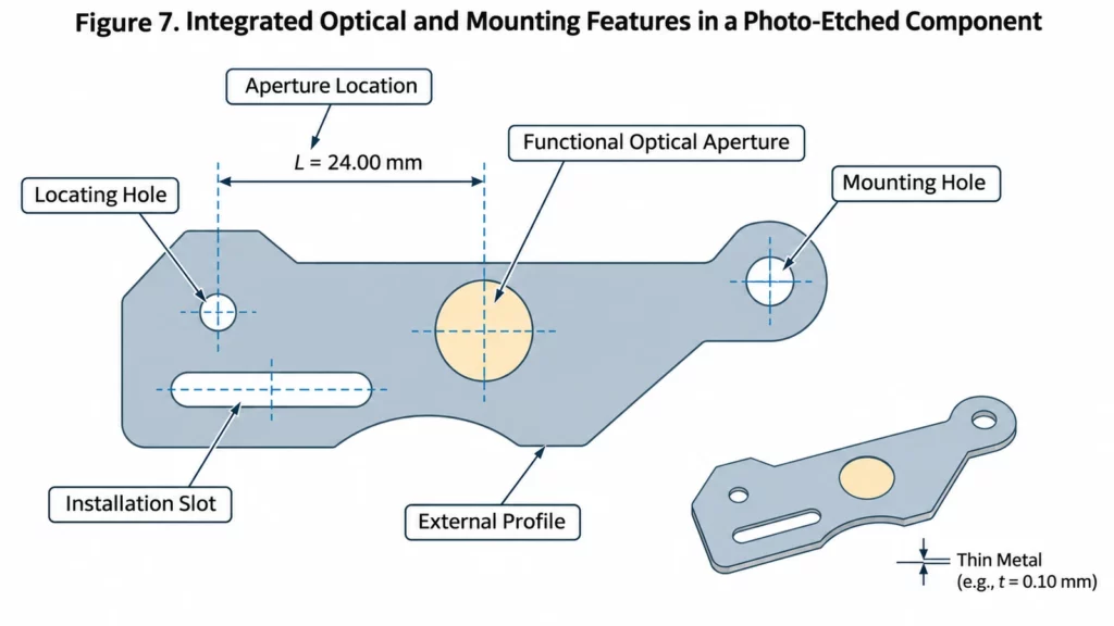
Consider a thin rectangular metal plate that contains:
- A central circular aperture.
- Two locating or mounting holes.
- An elongated installation slot.
- An asymmetric external profile.
Photochemical etching allows these planar features to be defined in a common pattern.
Instead of treating the optical aperture and its mounting structure as separate components, engineers can evaluate whether both functions can be incorporated into the same metal sheet.
This approach may reduce the number of assembly interfaces, depending on the surrounding design.
Define the Optical Opening Relative to the Mounting Datums
When combining optical and mechanical features, the drawing must communicate which features establish the component’s position.
A screw clearance hole and a locating pin hole do not necessarily serve the same purpose. The former may provide fastening clearance, while the latter may establish a repeatable position.
The critical aperture should therefore be located relative to the appropriate functional mounting reference.
Established geometric dimensioning and tolerancing principles provide a framework for specifying datum references, feature locations, and geometric tolerances.
For an etched optical aperture, two requirements should be distinguished:
- The opening must have the correct functional geometry.
- The opening must occupy the required position relative to the assembly references.
By defining both requirements, engineers can evaluate photochemical etching as a manufacturing route for the complete optical component, not merely for an individual hole.
TMNetch Manufacturing Example: Photo-Etched Copper Optical Apertures
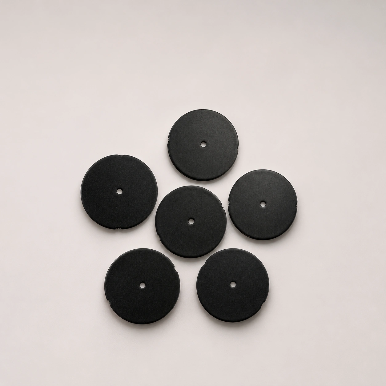
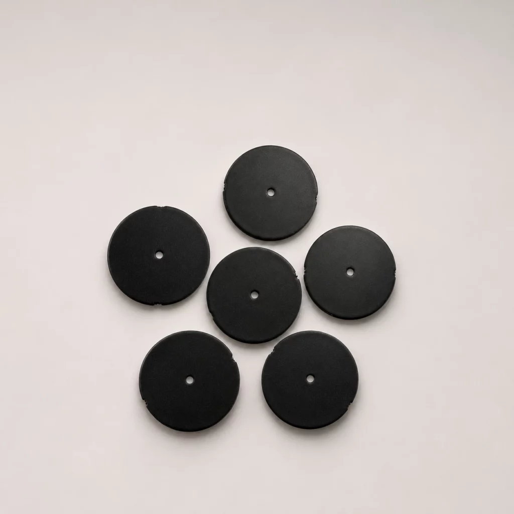
A practical example of photochemical etching in optical component manufacturing is a custom copper aperture previously produced by TMNetch.
The component features a circular thin-metal profile, a sub-millimeter central through-opening, and a matte black finish.
Key manufacturing characteristics include:
- Thin copper material with a thickness in the 0.1 mm range.
- A precision central through-aperture.
- A circular external profile manufactured by photochemical etching.
- A matte black surface finish specified for optical applications.
Although the component has a relatively simple geometry, its manufacturing requirements extend beyond producing a small hole in a metal sheet. The central opening must be evaluated together with the material thickness, etched edge profile, and surrounding light-blocking geometry.
Photochemical etching provides a manufacturing route for defining both the internal aperture and the external profile within the same thin-metal component. The process avoids the mechanical shearing action associated with punching, making it worth considering for delicate metal foils and precision opening patterns.
This example also highlights the importance of distinguishing between a surface opening and the actual through-opening. For optical applications, the relevant aperture geometry should be defined according to the intended light direction and evaluated through the material thickness.
When a surface finish is required, the critical opening dimensions should also be considered in the finished component condition.
This manufactured example demonstrates TMNetch’s experience with thin copper components that combine small through-apertures, custom external profiles, and application-specific surface requirements.
The same manufacturing approach can be evaluated for custom optical apertures, precision slits, optical masks, and light shields, subject to the required geometry, material thickness, and functional tolerances.
What Determines Whether an Optical Aperture Can Be Photo Etched?
The suitability of photochemical etching depends on several related design variables rather than a single minimum opening dimension.
The following four questions provide a useful starting point.
1. Is the Material Thickness Compatible With the Opening?
Stainless steel, nickel alloys, and other suitable metals can be processed by photochemical machining, subject to the material-specific manufacturing conditions.
Thinner material generally provides a starting point for evaluating smaller openings because less material must be removed through the thickness.
However, reducing thickness can also affect handling stiffness and the stability of the surrounding features.
The objective is to select a thickness that supports both the required aperture geometry and the mechanical needs of the component.
2. Are the Opening and Remaining Webs Within Demonstrated Process Limits?
Minimum opening dimensions and remaining web widths depend on material thickness and manufacturing capability.
Published chemical etching design guidelines illustrate that the applicable minimum hole and slot dimensions can change across different material thickness ranges.
A useful preliminary review is to compare the smallest required opening with the sheet thickness.
However, this ratio does not independently determine whether the aperture is manufacturable. Material grade, profile requirements, corner geometry, and allowable dimensional variation also need consideration.
3. Can the Functional Opening and Edge Profile Meet the Requirement?
A drawing tolerance must be evaluated in relation to the size of the feature.
For example, a ±0.010 mm width tolerance represents a ±10% variation for a 0.100 mm slit, but only ±2% for a 0.500 mm opening.
The same absolute manufacturing tolerance can therefore represent significantly different geometric requirements.
For critical optical features, the required tolerance should come from the application rather than a general supplier capability figure.
A tolerance of ±0.01 mm may be evaluated for suitable features, but its feasibility must be confirmed for the specific material, thickness, geometry, and measurement method.
Photochemical etching should not be selected solely because a nominal tolerance appears achievable. The required through-opening and edge profile must also be verified.
4. Does the Complete Component Remain Suitable After Processing?
Aperture geometry is only part of the finished component.
The engineer should also review the remaining webs, mounting features, flatness, part separation, and required surface finish.
Chemical etching avoids the mechanical shearing mechanism associated with punching, but an etched edge can still contain a characteristic cusp or undercut.
Similarly, an aperture that will receive a blackened finish or another surface treatment should have its critical dimensions verified in the required final condition.
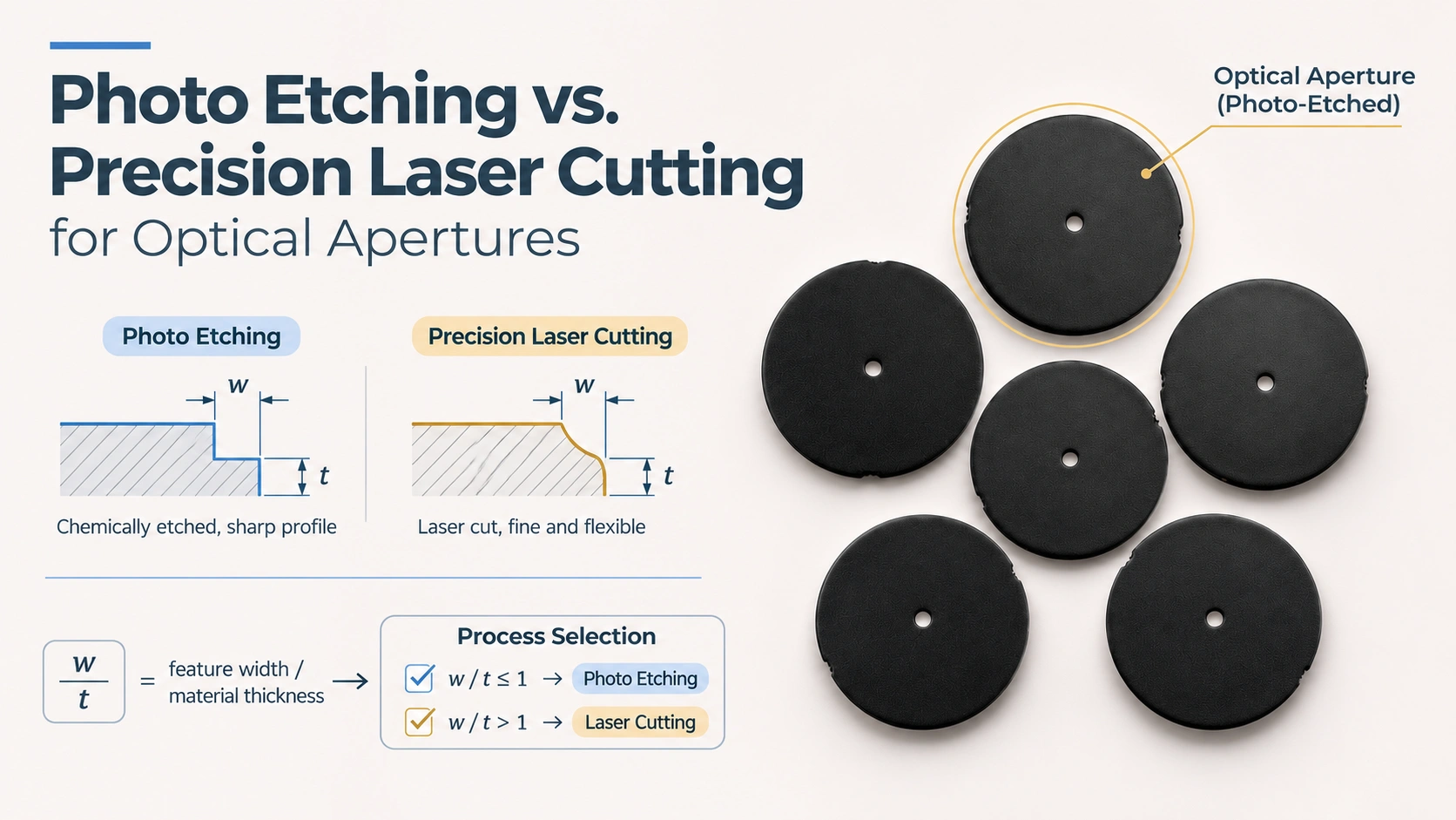
If the design demands an exceptionally small opening, a specialized sidewall profile, or tolerances beyond demonstrated etching capability, precision laser micromachining or electroforming may offer a more suitable route.
Selecting photochemical etching means matching the process to the component’s requirements—not forcing every optical design into the same manufacturing method.
How to Specify a Custom Optical Aperture for Photo Etching
A well-prepared drawing makes it easier to evaluate the manufacturability of an optical aperture before producing samples.
Start with the intended functional opening and identify how that opening relates to the rest of the component.
For a circular aperture, clarify whether the diameter applies to a surface boundary or the unobstructed through-opening. For a slit, specify the relevant width, effective length, and edge requirements.
If the component has a preferred light direction, include its orientation relative to the metal surfaces.
Optical Aperture RFQ Checklist
| Information to provide | Manufacturing purpose |
|---|---|
| Material grade and condition | Establish the material-specific processing requirements |
| Metal thickness | Evaluate feature dimensions and aperture profiles |
| Opening geometry | Define the required circular, rectangular, or custom shape |
| Functional through-opening | Establish the boundary that must remain unobstructed |
| Critical dimensions and tolerances | Identify the geometry that requires close control |
| Light direction or installation orientation | Evaluate directional aperture profiles |
| Edge profile requirements | Define acceptable sidewall and edge conditions |
| Mounting features and datums | Control aperture position within the assembly |
| Final surface finish | Establish the required finished component condition |
| Inspection method | Align the manufacturer and customer on measurement requirements |
| Sample and production quantities | Support prototype and production planning |
For a critical aperture, the measurement method should be agreed upon before production.
A surface image may be appropriate when the drawing specifies a surface boundary. A validated transmitted-light measurement may be more relevant when the requirement concerns a geometric through-opening along a defined direction.
Specialized applications may require additional edge-profile measurements or calibrated aperture-area inspection.
The appropriate method depends on the dimensional requirement and the measurement uncertainty that can be achieved.
By defining these requirements together, engineers can develop photo-etched optical components around the needs of the actual optical assembly rather than relying on a generic hole-size specification.
Frequently Asked Questions
Can optical apertures be manufactured by photochemical etching?
Yes. Photochemical etching is an established manufacturing option for suitable thin metal optical apertures, including circular openings, rectangular windows, slit patterns, and custom light shields. Feasibility depends on material thickness, feature dimensions, edge profiles, and required tolerances.
What is the difference between an aperture’s surface opening and its functional through-opening?
The surface opening is measured at one face of the metal. The functional through-opening is the unobstructed geometric region available along the specified light direction. Differences in sidewall shape or alignment through thickness can cause these boundaries to differ.
Can photo etching produce rectangular optical windows and complex aperture shapes?
Yes. Phototool-based manufacturing can define rectangular windows and custom two-dimensional profiles. Achievable corner radii, minimum features, and remaining web widths must be reviewed against the material thickness and process capability.
Can precision optical slits be photo etched?
Suitable optical slits can be evaluated for photochemical etching, particularly when they are integrated with additional openings or mounting features. Extremely narrow slits, demanding sidewall profiles, or exceptionally tight tolerances may require precision laser micromachining or electroforming.
Can mounting holes and optical apertures be etched in the same component?
Yes. Optical openings, locating holes, mounting slots, and external profiles can be defined in a common phototool pattern. Their relative positions and tolerances must be specified according to the component’s assembly requirements.
Conclusion
A precision optical aperture is more than a hole in a metal sheet. Its functional geometry depends on the relationship between the opening dimensions, material thickness, edge profile, and mounting position.
Photochemical etching provides a practical manufacturing option for thin-metal optical apertures, precision slits, custom windows, masks, and light shields when these requirements fall within demonstrated process capabilities.
Its value becomes particularly clear when a component combines several optical openings with locating and mounting features.
At TMNetch, we provide customized photochemical etching services for precision metal components. For a new optical aperture project, the starting point is the drawing and the functional opening that needs to be controlled.
By reviewing the material, thickness, opening geometry, and assembly requirements together, we can help evaluate whether photo etching is an appropriate manufacturing route for your component.
Have a custom optical aperture, slit, or light shield design?
Contact TMNetch to discuss your drawing, critical opening requirements, and prototype manufacturing needs.