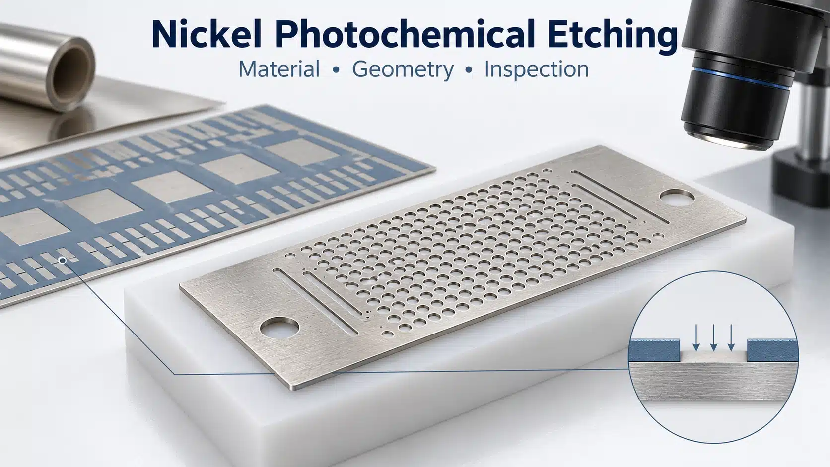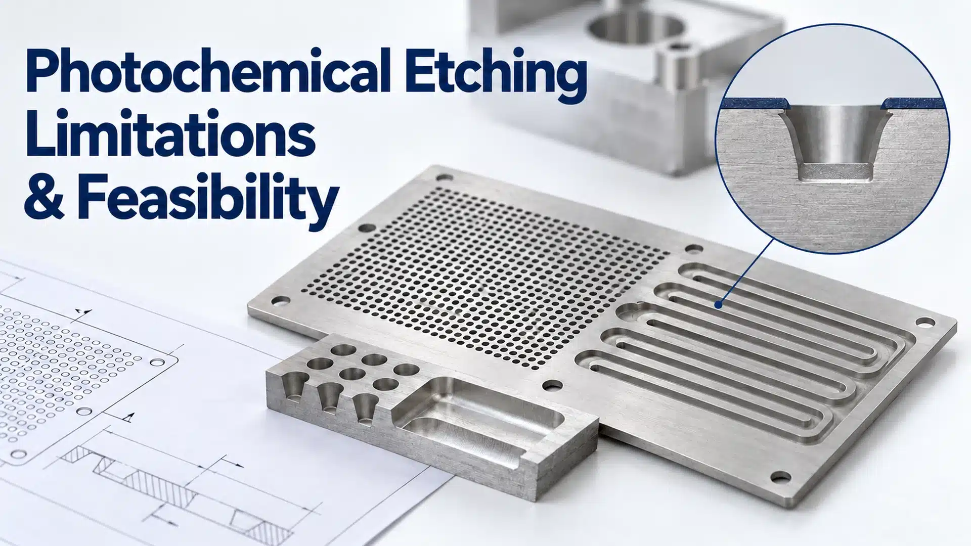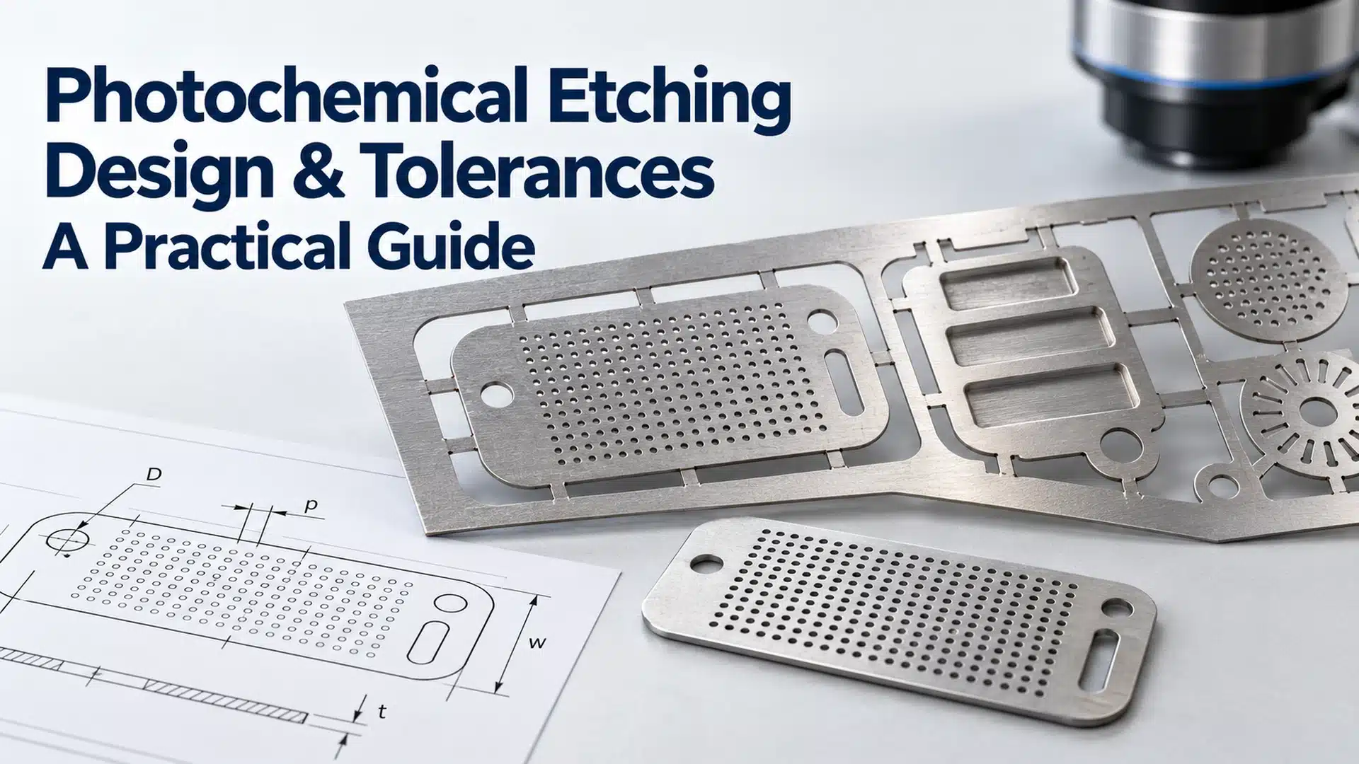

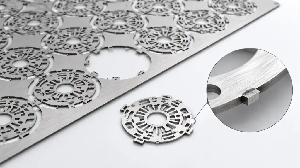
Small connection points on photo-etched parts are often intentional retaining tabs, not manufacturing defects. These metal bridges keep parts attached to the production sheet. However, their position and the marks left after removal must meet the drawing and functional requirements.
For buyers evaluating chemical etching services, the question is not simply whether tabs are visible. It is whether the finished edge remains suitable for assembly, sealing, contact or appearance. A planned tab can still create a nonconforming part if its residue exceeds the agreed limit.
Key Takeaways
- A retaining tab is a designed connection between a part and its production sheet.
- The bridge before separation and the edge mark after separation are different inspection items.
- Tab location matters as much as tab size.
- Tab-free production is possible for some designs, but requires a separate manufacturing review.
- Compare complete process routes, including separation, finishing and inspection.
A Customer Question About a Small Connection Point
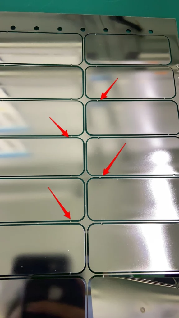
In a previous TMNetch etching order, a customer noticed small connection points around the parts. The customer asked whether these points indicated a production defect.
The factory explained that they were deliberately retained connections. Their size could be reduced where the design and processing conditions allowed. The customer accepted them on the condition that they did not affect the finished part’s functional area.
This case illustrates the difference between explaining a process and defining acceptance. Understanding why a feature exists resolves one concern. Confirming where it may remain resolves another.
For repeat orders, the practical next step is to record that condition in the drawing or an approved tab-layout document. “Does not affect function” should become a clear location, dimension or inspection requirement.
What the Connection Points Actually Are
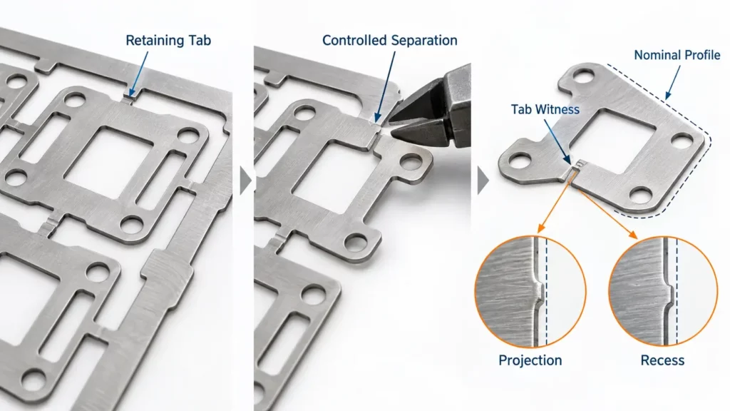
Photochemical etching, also called photochemical machining, uses patterned photoresist to protect selected metal areas while an etchant removes exposed material. A retaining tab is included in that pattern so a small bridge remains between the part and the surrounding sheet.
| Term | What it describes | What to check |
|---|---|---|
| Retaining tab, etch tag or tie-in | Metal bridge before separation | Location, width and panel stability |
| Tab witness or tab remnant | Local mark after separation | Projection, notch depth and damage |
| Dropout part | Part etched free without retaining tabs | Edge quality, dimensional control and handling |
ASM International’s handbook overview of photochemical machining identifies dimensional limitations, tolerances and edge quality as design considerations. For tabbed parts, review these requirements after separation, as well as in the production panel.
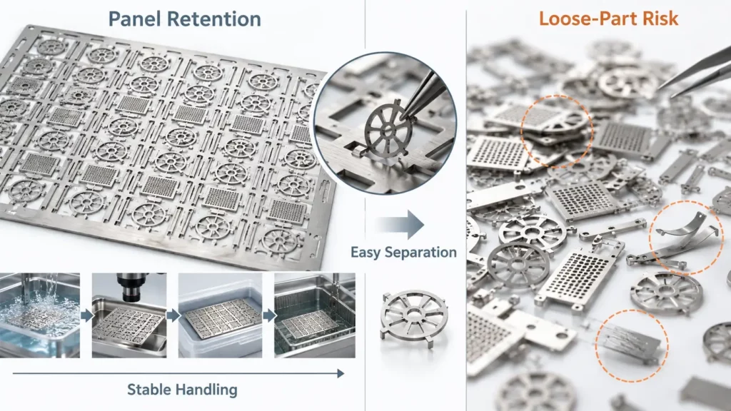
An intact-panel photograph shows retention, not the final edge condition after separation.
Why Retaining Tabs Are Used in Photochemical Etching
The Photo Chemical Machining Institute’s process overview describes patterning sheet metal with photoresist, chemically removing exposed metal, then stripping and inspecting the parts. In a tabbed layout, selected bridges remain between the part and the surrounding sheet.
Use the production review to establish why panel retention is needed, who will separate the parts and where separation marks are permitted. Include any later plating, assembly or transport requirements.
These benefits create a trade-off. The bridge must survive the required handling, but it should also separate without excessive force or unacceptable edge damage.
The engineering target is therefore not the smallest tab at any cost. It is the smallest reliable tab that meets the finished-part requirement.
When Is a Tab Acceptable—and When Is It a Defect?
A planned feature is not automatically acceptable. The following review matrix is a practical framework for agreeing requirements, rather than a universal inspection standard.
| Review item | Potentially acceptable | Requires correction or approval |
|---|---|---|
| Location | Approved non-functional edge | Sealing, mating or contact edge |
| Remaining material | Within the specified edge envelope | Projection beyond the allowed profile |
| Recess | Approved local relief | Notch entering required material |
| Separation damage | Controlled local witness | Crack, tear or permanent distortion |
| Appearance | Meets the agreed visual criterion | Fails the cosmetic specification |
| Consistency | Matches the approved sample | Unexplained variation across the batch |
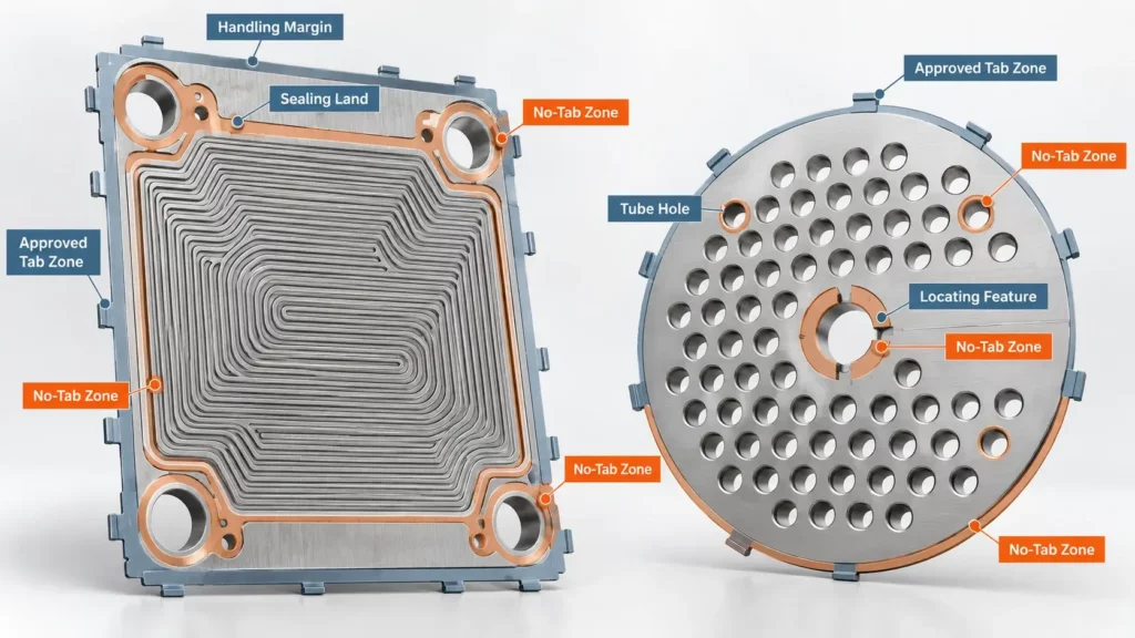
Start by identifying the edge’s job. A non-mating outer border may tolerate a small witness. A locating edge, gasket contact region or optical opening may require a different tab position or additional finishing.
For a heat exchanger flow plate, distinguish the handling margin from the sealing land and bonding surface. For a baffle plate, distinguish a non-critical outside edge from tube holes and locating features. These are proposed review priorities, not evidence that every plate can accept tabs in the same place.
If the drawing prohibits projections, a customer’s general acceptance of tabs does not override that requirement. Obtain approval for the specific condition or remove the residue within the permitted geometry.
Controlling Tab Size, Location and Removal
Start With Location
Mark no-tab zones before the supplier prepares the production layout. Identify functional edges, visible surfaces and areas that must remain continuous.
Review proposed locations with the supplier against handling, separation and finishing requirements. Leave access for the agreed removal method and check the resulting edge on a representative sample.
Balance Width and Quantity
Agree tab width and quantity using the material, thickness, part geometry and handling needs. Ask the supplier to justify the layout rather than specifying “as small as possible” without acceptance criteria. Tab geometry should also be reviewed together with the applicable photochemical etching tolerances and design limits.
Reducing width or quantity is a design change that should be checked on a representative sample. The relevant outcome is not only easier separation, but an undamaged part after the full process route.
Select the Tab Geometry
An external tab places the connection outside the nominal contour. A recessed tab moves the break point inward, avoiding an outward projection but leaving a local notch. Partial etching can reduce bridge thickness to assist separation.
For undefined edge conditions, ISO 13715 provides rules for indicating and dimensioning edges on technical drawings. It does not prescribe a retaining-tab size. Specify the permitted projection or recess for the part.
Define Separation and Finishing
Specify whether parts will arrive in sheets or individually separated. If the customer removes them, agree the removal method and who checks the resulting edge.
Where finishing is needed, define the final geometry rather than only requesting “deburring.” The operation must remove unacceptable residue without taking away required material or deforming the part. When separation, edge finishing, inspection, and other secondary operations must be coordinated, a one-stop chemical etching and finishing service can simplify process responsibility.
Tabs, Burrs, Dross and Etching Defects Are Different
Do not use “burr” as a catch-all description for every edge feature. Different causes require different corrective actions.
A retaining tab is intentional. A tab witness results from separating that connection. By contrast, an unexpectedly unetched bridge may indicate incomplete material removal rather than a designed tab.
Over-etching means too much metal has been removed from the required geometry. A crack or tear at a tab location is separation damage. Neither should be accepted merely because the part was manufactured with tabs.
The Open University’s explanation of photochemical machining describes burr-free chemical removal without introducing thermal or mechanical stresses. That description concerns the etching operation. Mechanical tab separation is a separate step and can leave a localized projection or fracture mark.
Accordingly, “burr-free etched features” should not be interpreted as a promise that every detached part requires no edge review.
Chemical Etching vs Laser Cutting, Stamping and CNC Machining
Tabs are not exclusive to etching. TRUMPF documents micro joints and nano joints that retain laser-cut parts in the sheet. Its guidance also distinguishes the more visible marks from conventional micro joints from the smaller marks produced by nano joints.
Autodesk’s machining documentation likewise describes tabs that hold parts during contour machining. Switching processes therefore does not necessarily eliminate retention features.
| Process | Retention approach | Edge condition to review | Useful selection direction |
|---|---|---|---|
| Photochemical etching | Tabs or dropout production | Tab witness and etched profile | Thin, intricate two-dimensional parts |
| Laser cutting | Micro joints, nano joints or other support | Joint marks, thermal effects and possible dross | Larger contours and thicker sheet |
| Stamping | Die-specific carriers and part release | Sheared edge, fracture region and burr | Stable designs with repeat demand |
| CNC machining | Fixtures or contour tabs | Tool marks, burrs and tab-removal areas | Three-dimensional or locally machined features |
For stamping, Dayton Lamina’s die-clearance guidance links edge quality to punch-to-die clearance, material and required burr height. This demonstrates the same principle: edge quality depends on controlled process details, not simply the process name.
Compare quotations for the same delivered condition, including tooling, separation, finishing, inspection and packaging.
A Better Process-Selection Method
The TMNetch case suggests a useful decision sequence: resolve the functional risk before replacing the manufacturing process.
- Map critical areas. Identify where projections, notches, thermal effects or tool marks are prohibited.
- Check geometry and material. Review thickness, openings, narrow sections and three-dimensional features.
- Define the delivered condition. Choose retained panels or loose parts and specify required edge finishing.
- Compare production economics. Include quantity, design changes, tooling and inspection costs.
- Approve representative samples. Inspect the edge after all separation and finishing operations.
For a thin, complex part, relocating tabs may preserve the advantages of etching while resolving the edge concern. If no location can accommodate a bridge or its witness, assess dropout production or a different retention method.
For thicker or three-dimensional parts, another process may be more suitable regardless of tab concerns. Review the broader photochemical etching tolerances and material limits before making that decision.
The useful question is: which route produces a conforming, assembly-ready part at an acceptable total cost?
What to Specify on the Drawing or RFQ
Provide the material grade, thickness, part dimensions, quantity and critical tolerances. Add tab-specific instructions covering:
- Permitted and prohibited locations;
- Whether the supplier must submit a tab layout for approval;
- Panelized or individually separated delivery;
- Maximum outward residue and inward notch;
- Separation, finishing and inspection responsibilities;
- Cosmetic, sharp-edge and cleanliness requirements.
A starting drawing note could read:
Retaining tabs are permitted only at approved locations outside functional areas. After separation, projections and recesses shall meet the specified edge limits. Cracks, tears and distortion outside the drawing requirements are not permitted.
Add measurable limits where needed. “Tabs acceptable” does not explain how far a mark may extend or where it may occur. For drawings using the ASME system, ASME Y14.5 provides the language for defining and interpreting geometric requirements.
Frequently Asked Questions
Are retaining tabs on photo-etched parts defects?
Not by themselves. They are designed retention features. The finished part must still meet its drawing, approved layout and functional requirements.
Can photo-etched parts be made without tabs?
Some designs can use dropout production. Ask the supplier to confirm dimensional capability, handling and packaging for that route.
Do tabs affect dimensional tolerance?
The retention strategy can affect achievable tolerances. Evaluate the complete part and process; tab presence alone does not establish accuracy.
Can tab marks be removed completely?
A visible projection may be removable through suitable finishing. A recessed notch needs separate consideration because material has already been removed. Specify the acceptable final contour.
Where should tabs not be placed?
Exclude locations where the bridge or separation mark would violate sealing, fit, contact, optical, safety or appearance requirements.
Are tabs unique to chemical etching?
No. Laser cutting and contour machining also use retention connections. Their geometry and removal behavior differ.
Should tab locations appear on the drawing?
For edge-sensitive parts, show them on the drawing or approve a separate supplier layout before production.
Review the Edge Requirement Before Production
The customer accepted the connection points outside the functional area. Make that boundary explicit before production starts.
For your next photo-etching project, include critical edges and the required delivery condition with the drawing. Submit your photo-etched part drawing for a manufacturability review to discuss tab placement, separation, finishing, and whether etching or a combined manufacturing route fits the part.
A retaining tab is a designed feature. Acceptance of its final witness is an engineering and quality decision.