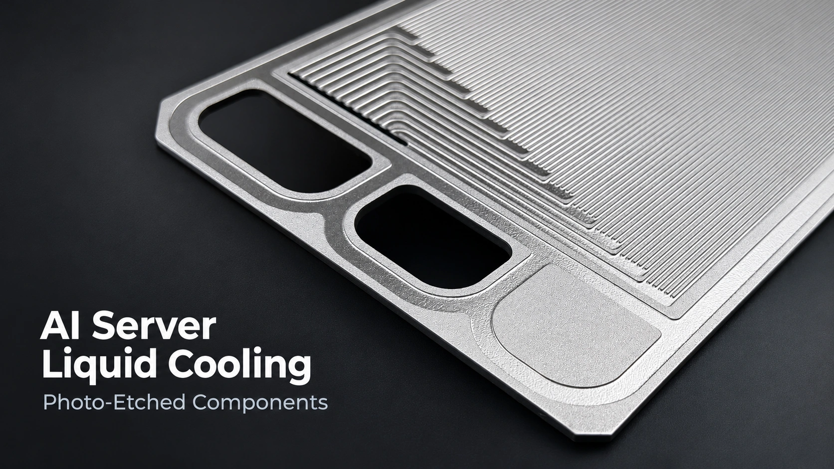

AI server liquid cooling systems rely on cold plates, manifolds, coolant distribution units (CDUs), and heat exchangers to manage heat generated by high-power processors.
Each component has different manufacturing requirements. While thick structural parts often require CNC machining or forming, selected thin-metal components can be produced using photochemical etching, particularly microchannel flow plates, distribution layers, and precision spacers.
For OEM engineers, the important question is not whether an entire cooling system can be chemically etched, but which individual components are suitable for etching and how to evaluate their manufacturability.
Key Engineering Conclusions
- System components: AI liquid cooling systems typically include cold plates, manifolds, CDUs, quick disconnects, tubing, and filtration components.
- Etching opportunities: Photochemical etching can produce selected microchannel flow plates, distribution layers, precision shims, and compact heat exchanger plates.
- Manufacturing boundaries: Thick cold plate bases, manifold bodies, and pressure-containing assemblies generally require additional machining, forming, joining, or testing.
- Critical distinction: An etched flow layer is not a complete, pressure-qualified liquid cold plate.
- OEM design review: Manufacturing feasibility depends on material grade, sheet thickness, channel geometry, joining method, and inspection requirements.
Why Does AI Server Liquid Cooling Require Precision Metal Components?
As AI processors become more power-dense, removing heat through conventional air cooling becomes increasingly challenging. Higher heat loads require greater airflow, larger heat-transfer surfaces, or alternative cooling arrangements. Liquid cooling transfers heat from processors through cold plates and a circulating coolant to external heat exchange equipment.
NVIDIA AI Servers: An Example of Rack-Scale Liquid Cooling
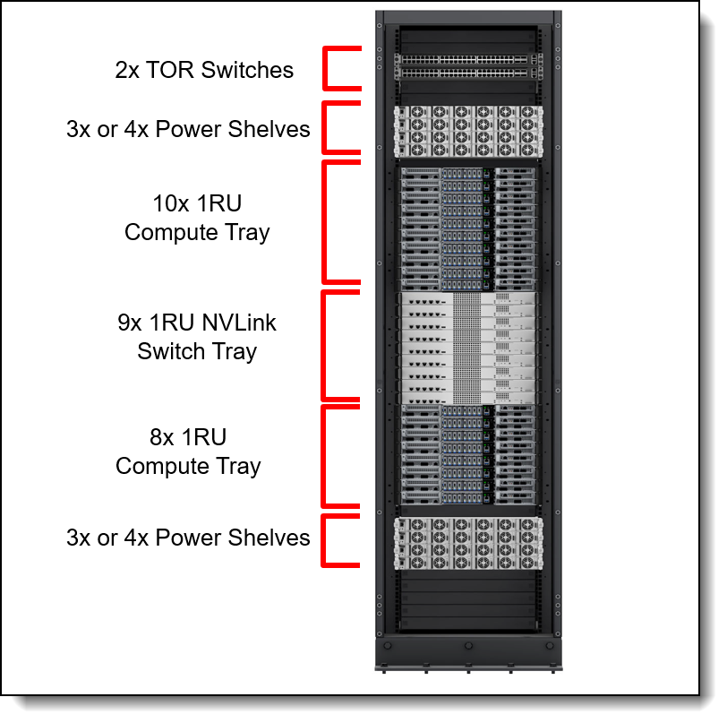
The NVIDIA GB300 NVL72 rack-scale platform illustrates how liquid cooling is integrated into modern AI infrastructure.
The platform contains 72 NVIDIA Blackwell Ultra GPUs and 36 Grace CPUs. In Lenovo’s implementation, the CPUs, GPUs, and NVSwitch components use liquid cooling, while certain supporting components remain air-cooled.
The published GB300 reference configuration distributes approximately 90% of the rack’s heat load to liquid cooling and 10% to air cooling.
This is a useful distinction: a liquid-cooled AI rack does not necessarily eliminate air cooling.
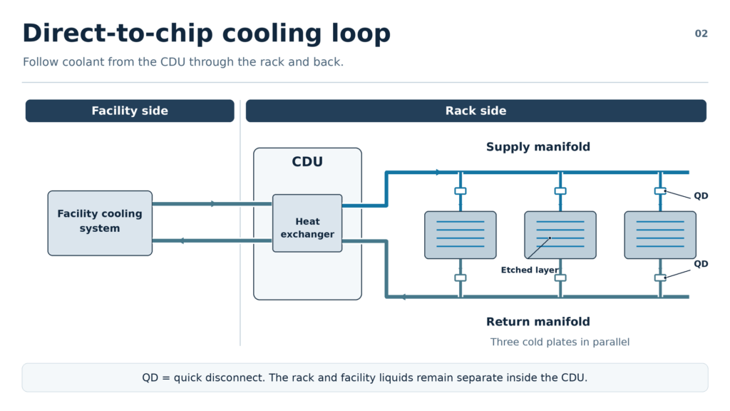
The liquid cooling architecture includes cold plates, rack manifolds, quick disconnects, and a CDU. Each assembly performs a different function, and each requires a different manufacturing approach.
For precision metal manufacturers, the most relevant opportunities are often found inside the assemblies rather than in the complete cooling equipment.
Three Types of AI Server Liquid Cooling and Their Etching Opportunities
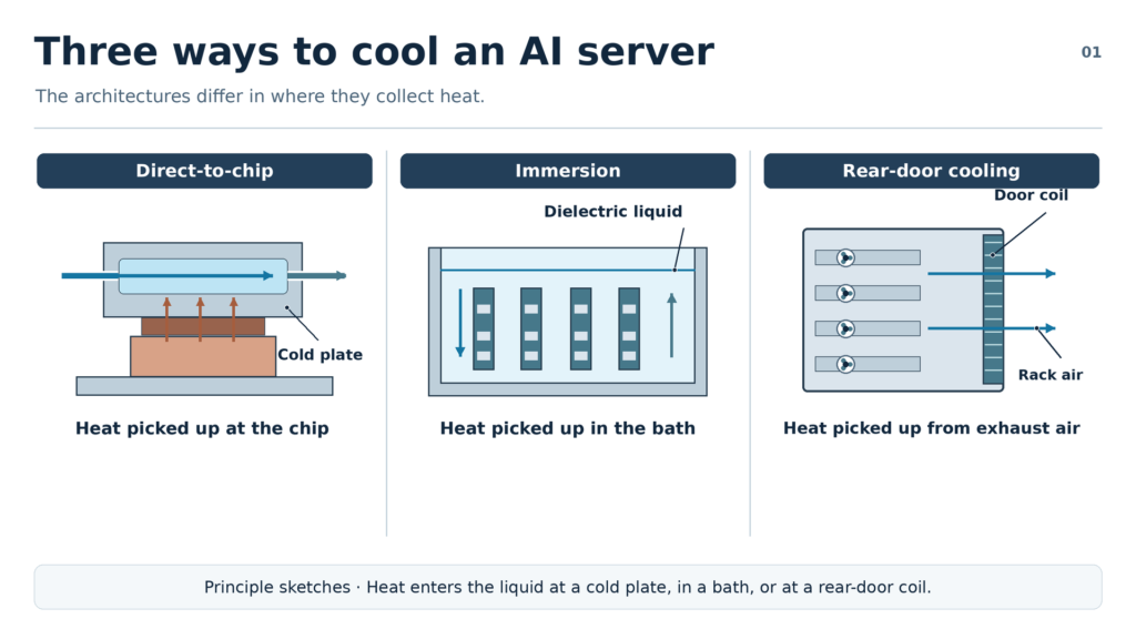
Data center liquid cooling is commonly divided into direct-to-chip, immersion, and rear-door heat exchanger systems. Their main difference is where heat is collected and how it reaches the liquid cooling circuit.
| Cooling Method | How Heat Is Removed | Potential Etched-Metal Components |
|---|---|---|
| Direct-to-Chip | Coolant flows through cold plates attached to GPUs, CPUs, or other high-power components. | Microchannel flow layers, distribution plates, precision spacers |
| Immersion Cooling | Electronic equipment is immersed in a dielectric liquid that transfers heat to a cooling system. | Selected heat exchanger and liquid distribution components |
| Rear-Door Cooling | A liquid-cooled heat exchanger captures heat from air leaving the server rack. | Selected thin heat exchanger plates and internal flow components |
Why Direct-to-Chip Cooling Matters Most for Metal Etching
Direct-to-chip cooling brings liquid close to concentrated heat sources through a cold plate. Depending on the design, internal passages may be formed through machining, skiving, or stacked patterned metal layers.
The liquid circuit generally follows this path:
CDU → Supply Manifold → Quick Disconnects → Cold Plates → Return Manifold → CDU
The CDU transfers heat to the facility cooling system, while the manifolds distribute and collect coolant. Filters help control particulate contamination within the circuit.
The Open Compute Project cold plate requirements identify coolant compatibility, flow distribution, filtration, and operating conditions as important system-level considerations.
For component manufacturers, direct-to-chip cooling offers a clear opportunity to evaluate thin metal flow layers and precision internal features rather than entire cooling assemblies.
Which AI Liquid Cooling Components Can Be Made by Chemical Etching?
Photochemical etching removes selected areas of metal from a patterned sheet. It can create partial-depth channels, through-holes, slots, and complex external profiles without using a cutting tool to machine each individual feature.
Its suitability depends on the material, sheet thickness, feature geometry, and required tolerances.
| Component | Suitable Etched Features | Manufacturing Boundary |
|---|---|---|
| Microchannel Flow Plates | Shallow channels, ports, repeated flow patterns | Joining and pressure testing remain separate |
| Flow Distribution Plates | Branching channels, orifice patterns, alignment holes | Hydraulic performance requires validation |
| Precision Shims & Spacers | Thin profiles, cavities, positioning holes | Not automatically qualified as liquid seals |
| Compact Heat Exchanger Plates | Flow passages, distribution openings, layered patterns | Requires suitable joining and core qualification |
| Metal Filter Screens | Custom apertures and protective screen profiles | Filtration performance must match system requirements |
1. Microchannel Cold Plate Flow Layers
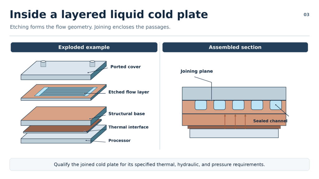
Microchannel cold plates use small internal passages to transfer heat from a processor into the circulating coolant.
In suitable layered designs, photochemical etching can form these passages in metal sheets before the layers are joined.
A typical manufacturing sequence is:
Metal Sheet → Channel Etching → Dimensional Inspection → Layer Alignment → Joining → Assembly Testing
The etched layer must be designed around several connected dimensions:
- Channel width and depth
- Channel pitch and minimum ligament width
- Remaining wall thickness
- Inlet and outlet geometry
- Alignment and joining surfaces
Smaller channels can increase heat-transfer surface density, but they may also increase pressure loss and sensitivity to contamination. Channel geometry therefore requires both thermal and hydraulic evaluation.
The essential distinction is that chemical etching creates the flow geometry; subsequent joining and qualification establish the completed cold plate assembly.
For more detail, see photochemical etching for microchannel heat exchangers.
2. Flow Distribution and Orifice Plates
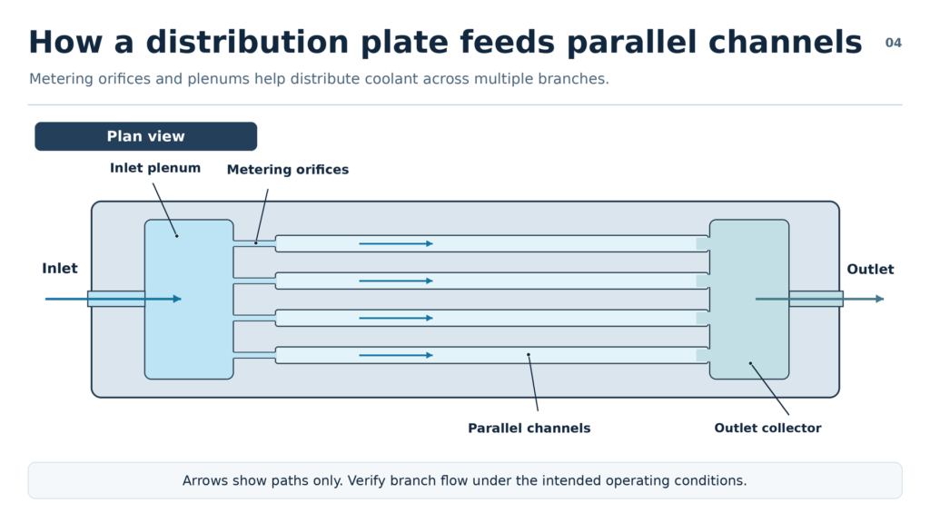
Cold plates with parallel channels require controlled coolant distribution to avoid uneven flow between different passages.
In some designs, thin metal distribution plates contain branching channels, repeated openings, or restricted flow paths.
Photochemical etching can be evaluated when these features are formed within suitable sheet material.
However, the manufactured hole pattern does not independently determine flow performance. Orifice geometry, coolant properties, operating pressure, and the surrounding fluid circuit affect the resulting distribution.
The designer must therefore verify hydraulic performance separately.
This application should not be confused with manufacturing an entire rack manifold, whose thick walls, pipe connections, and pressure-containing structure commonly require other processes.
3. Precision Shims and Spacer Layers
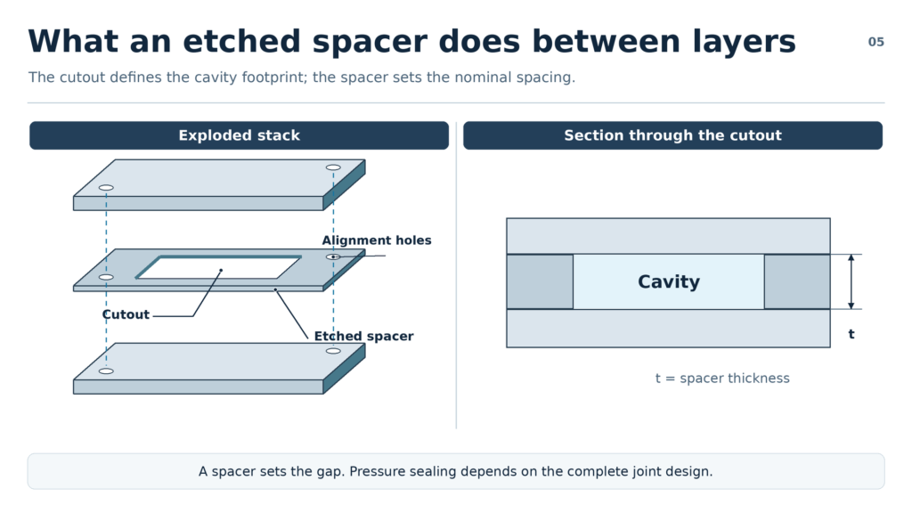
Layered cooling components may use thin metal spacers to define internal cavities, establish spacing, or align adjacent components.
Photochemical etching is suitable for evaluating complex two-dimensional profiles, closely spaced openings, and custom positioning features.
For example, a spacer may contain several internal cutouts and alignment holes that must match neighboring metal layers.
The key requirements are material thickness, dimensional accuracy, flatness, and assembly compatibility.
An etched spacer is not automatically a pressure seal. Sealing performance depends on the complete joint design and operating conditions.
TMNetch provides custom etched metal shims, washers, and spacers that can be evaluated against these types of geometric requirements.
4. Etched Plates for Compact Heat Exchangers
CDUs use heat exchangers to transfer energy between the technology cooling circuit and the facility cooling system.
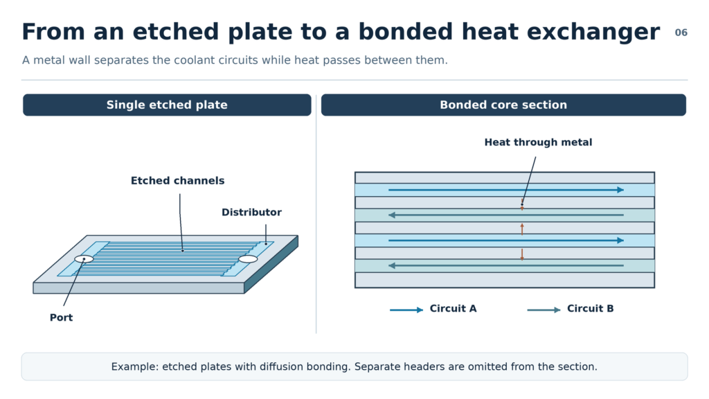
Some compact heat exchangers use patterned metal plates joined to form enclosed fluid passages.
For example, printed circuit heat exchangers can use etched flow patterns followed by diffusion bonding. The manufacturing principle is supported by research on diffusion-welded microchannel heat exchangers.
Etching can produce the individual flow plates, but joining surfaces, layer alignment, pressure resistance, and final inspection must be evaluated as part of the complete exchanger design.
Not every CDU uses an etched heat exchanger. Conventional formed-plate exchangers require different manufacturing routes.
For related design considerations, see can heat exchanger plates be made by chemical etching?.
5. Metal Filter Screens: A Conditional Application
Chemical etching can produce metal screens with custom opening shapes and external profiles. However, aperture size does not by itself establish filtration efficiency.
The OCP liquid cooling requirements connect filter selection to particulate contamination, component geometry, and system requirements.
TMNetch’s published metal mesh filter specifications list a minimum aperture of 0.1 mm (100 μm). Some microchannel cooling applications may require finer filtration than this.
Therefore, etched screens should be evaluated for appropriate protective or coarse-screening functions rather than assumed suitable for all coolant filtration applications.
Which Liquid Cooling Components Require Other Manufacturing Processes?
Chemical etching is not a universal substitute for CNC machining, metal forming, or joining.
A complete cold plate or cooling assembly may require several manufacturing processes, each selected according to the component geometry.
| Component or Feature | Typical Manufacturing Method | Main Consideration |
|---|---|---|
| Thin microchannel flow layer | Photochemical etching | Shallow, dense flow patterns |
| Thick cold plate base | CNC machining | Deep cavities and structural mounting surfaces |
| Skived cold plate fins | Skiving | Thin fins formed from a metal base |
| Rack manifold body | CNC machining, forming, welding | Pressure-containing connections |
| Quick disconnect body | Precision machining and assembly | Valves, sealing interfaces, mechanical connections |
| Formed heat exchanger fins | Stamping or forming | Three-dimensional fin geometry |
| Layered heat exchanger core | Etching plus qualified joining | Enclosed passages and joint integrity |
The most useful distinction is between a thin patterned flow layer and a thick structural cooling component.
A thin copper sheet containing many shallow channels may be suitable for photochemical etching, while a thick copper base with deep cavities may be better suited to CNC milling.
Some parts require a hybrid approach. Joining methods such as diffusion bonding, brazing, or welding introduce additional requirements for surface condition, alignment, and structural integrity.
Neither etching nor machining alone establishes the pressure rating of a completed liquid cooling assembly.
How Can OEMs Evaluate an Etched Liquid Cooling Component? Five DFM Steps
A design-for-manufacturing review should begin with the actual component drawing rather than a general assumption about the capabilities of chemical etching.
Step 1: Identify the Component Function and Material
Determine whether the part is a flow layer, distribution plate, spacer, or pressure-containing component.
Specify the exact metal grade, supply condition, and sheet thickness. For wetted parts, verify compatibility with the intended coolant and joining process.
Step 2: Review Channel Geometry and Remaining Wall Thickness
Check channel width, depth, pitch, minimum ligament width, and through-hole dimensions.
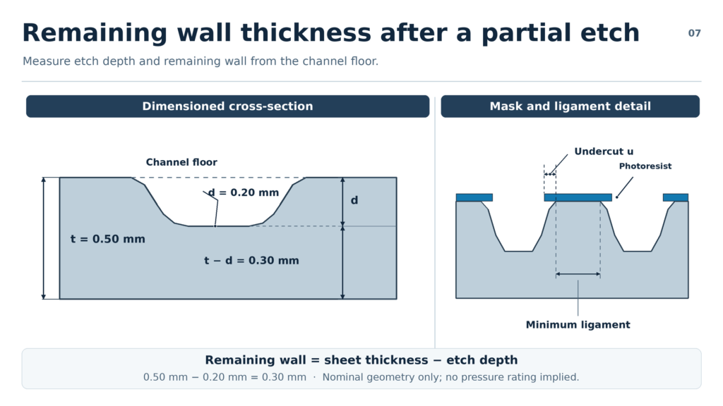
For a single-sided partial-depth channel, nominal remaining wall thickness is:
Remaining Wall Thickness = Sheet Thickness − Etch Depth
For example, a 0.50 mm sheet with a 0.20 mm-deep channel leaves a nominal 0.30 mm wall.
This is only a geometric example, not a validated etching specification or pressure-strength calculation.
Chemical etching also produces lateral material removal, or undercut, so the finished channel profile may differ from a rectangular CNC-machined groove.
See the etched heat exchanger plate thickness guide for further design considerations.
Step 3: Check Joining and Sealing Requirements
If the etched plate will be bonded, brazed, or welded to another layer, identify the intended joining surfaces and alignment requirements.
The joining process may affect finished channel dimensions. A completed pressure-containing assembly requires appropriate design verification and testing beyond individual plate inspection.
Step 4: Define Inspection and Cleanliness Requirements
Specify which dimensions are critical and how they will be measured.
Depending on the application, inspection may include channel geometry, thickness, hole position, flatness, and surface cleanliness.
Particulate contamination requires particular attention in small coolant passages. Final assemblies may also require leakage, pressure, and flow testing.
Related requirements are discussed in quality inspection for etched heat exchanger components.
Step 5: Confirm the Manufacturing Route
Determine whether the drawing is suitable for chemical etching alone or requires laser cutting, CNC machining, or other processes.
Review prototype quantity, anticipated production volume, critical tolerances, and downstream assembly requirements before finalizing the manufacturing method.
The objective of DFM is not to maximize the use of etching, but to identify the most suitable production route for the finished component.
What Information Should an OEM Include in an RFQ?
An effective request for quotation should identify both the component geometry and its intended application.
| Required Information | Key Details |
|---|---|
| Material | Grade, condition, specification |
| Sheet thickness | Nominal thickness and tolerance |
| Channel geometry | Width, depth, pitch, minimum ligament |
| Openings and ports | Dimensions, positions, tolerances |
| Surface requirements | Flatness, finish, joining surfaces |
| Joining process | Diffusion bonding, brazing, welding, or other |
| Operating conditions | Coolant, temperature, pressure |
| Inspection | Critical dimensions and acceptance criteria |
| Production | Prototype quantity and expected volume |
A dimensioned CAD drawing is the best starting point. Where requirements are still preliminary, identify them clearly so manufacturing feasibility can be reviewed without assuming unsupported tolerances.
TMNetch Case: Hybrid Manufacturing of Metal Flow Plates
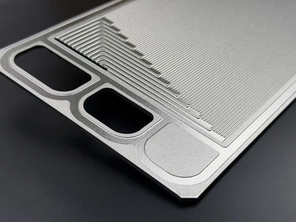
A TMNetch flow-plate manufacturing project used a hybrid route combining chemical etching and laser cutting for large patterned metal plates.
The project record included 316 stainless steel and titanium, with a largest recorded format of 600 × 1,400 mm and a stock envelope up to 4 mm. Fine flow features were assigned to etching, while larger structural cuts were handled using the process suited to those features.
The 4 mm figure describes the recorded stock envelope, not a universal through-etching capability.
Although this was not a documented AI server cold plate delivery, it demonstrates a relevant manufacturing principle: different features within one flow-plate drawing may require different processes.
For OEM liquid cooling development, this approach can help distinguish thin etched channels from larger mounting features, ports, and structural profiles.
Frequently Asked Questions
What components are used in AI server liquid cooling?
Direct-to-chip systems generally include cold plates, supply and return manifolds, quick disconnects, tubing, and a CDU. Filtration and monitoring components support coolant quality and system operation. The exact configuration depends on the cooling architecture.
Do NVIDIA AI servers use direct-to-chip liquid cooling?
Yes. NVIDIA GB300 NVL72 systems use liquid-cooled cold plates for major computing components, while selected supporting components remain air-cooled. The reference architecture includes manifolds, quick disconnects, and a CDU.
Can copper microchannel cold plates be manufactured using chemical etching?
Selected copper cold plate designs can use photo-etched metal flow layers. These layers require appropriate joining and assembly before becoming enclosed coolant passages. The complete cold plate must meet its specified thermal, hydraulic, and pressure requirements.
Is chemical etching better than CNC milling for liquid cooling components?
It depends on the geometry. Chemical etching is suitable for evaluating thin sheets with complex or repeated patterns, while CNC machining is often preferable for thick bases, deep cavities, and mechanical interfaces. Some assemblies benefit from both methods.
What drawings are needed to quote etched cooling components?
Provide a dimensioned drawing or CAD file showing material grade, thickness, channels, ports, and critical tolerances. Include joining requirements, inspection criteria, coolant conditions, and estimated production quantities to support an initial feasibility review.
Conclusion
AI server liquid cooling requires a combination of precisely manufactured components, but not every component is suitable for the same production process.
Photochemical etching offers a manufacturing route for selected thin-metal microchannel plates, distribution layers, spacers, and compact heat exchanger components. Thick structural bodies, pressure-containing connections, and completed cooling assemblies generally require additional processes and qualification.
For OEMs, the most effective approach is to evaluate each component’s material, geometry, joining method, and inspection requirements before selecting a manufacturing route.
Developing a Custom Liquid Cooling Metal Component?
TMNetch provides custom photochemical etching services for precision metal components in stainless steel, copper, titanium, nickel, and other suitable alloys.
Share your component drawing, material specifications, channel dimensions, and critical tolerances through our chemical etching service to discuss manufacturing feasibility and prototype requirements.