
Quick answer
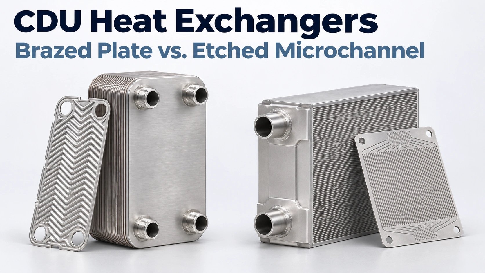
Use a brazed plate heat exchanger (BPHE) as the starting point for a single-phase, liquid-to-liquid coolant distribution unit (CDU). Consider an etched microchannel core when the available space, port positions, or internal flow layout calls for a custom design. Give both suppliers the same cooling duty and fluid conditions, then check which design can meet the target supply temperature within the flow and pressure limits of both loops.
What Does the Heat Exchanger Do in a Liquid-to-Liquid CDU?
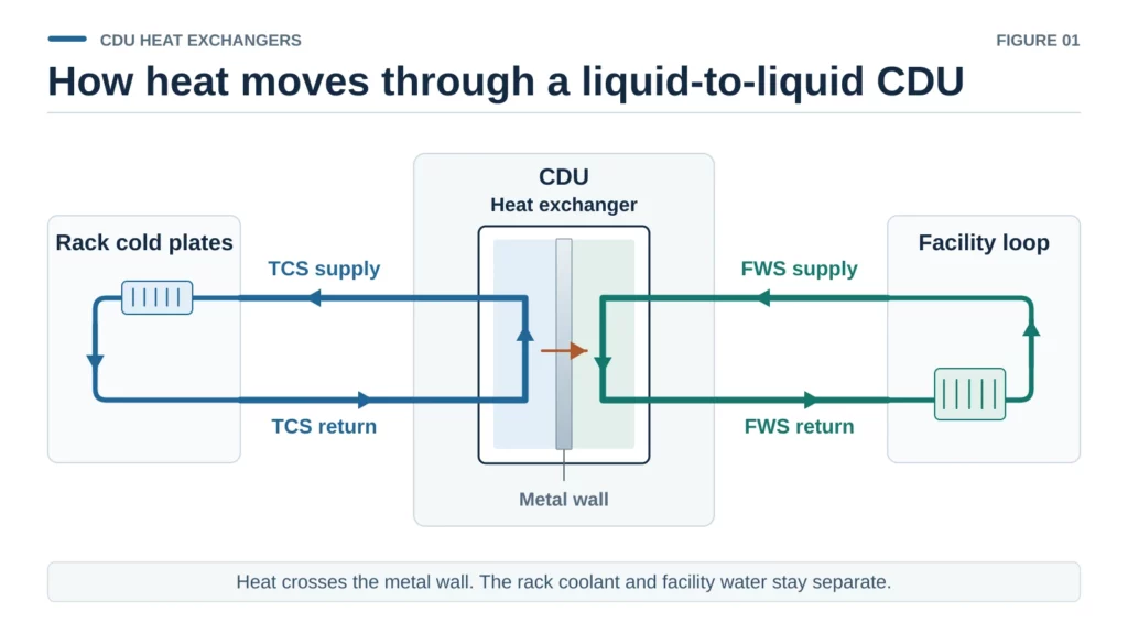
In direct-to-chip liquid cooling, cold plates pick up heat from the processors. The technology cooling system (TCS) carries that heat back to the CDU. Inside the heat exchanger, heat passes through metal walls into the facility water system (FWS). The fluids stay in separate passages, and the facility water leaves warmer than it entered.
Follow the flow at the CDU connections. The TCS supply is the cooled liquid leaving for the racks. The FWS supply is the facility water entering the CDU. Comparing those two temperatures tells you how close the unit can bring the rack coolant to the incoming facility water temperature. That temperature gap is one of the first requirements to put on a selection sheet.
How Does a Brazed Plate Heat Exchanger Work in a CDU?
Corrugated Plates and Brazed Joints
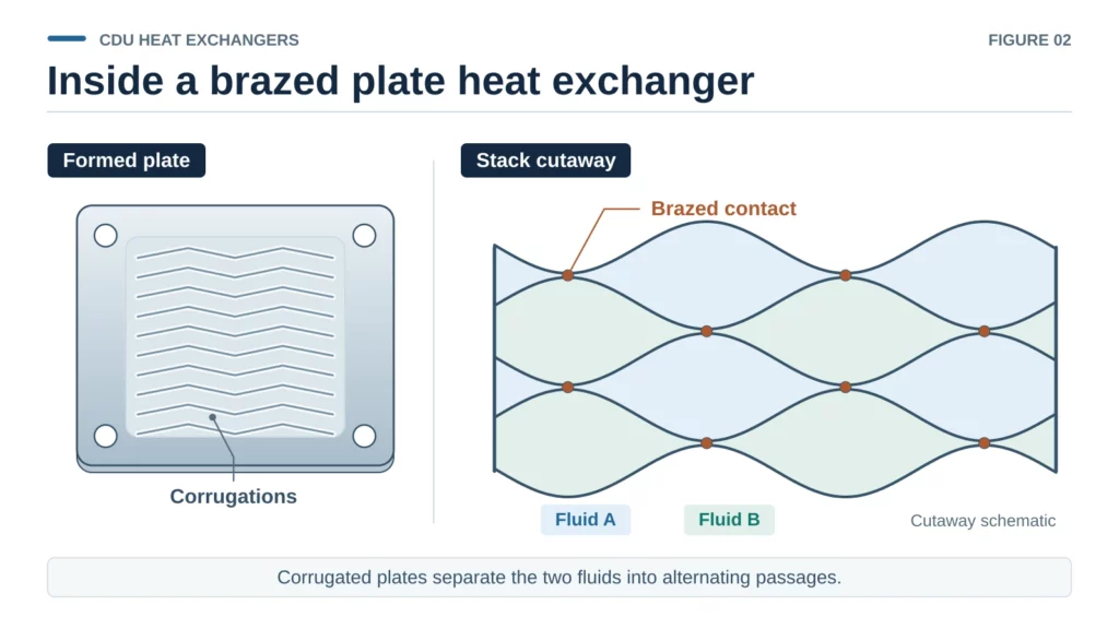
A conventional brazed plate heat exchanger stacks formed, corrugated metal plates. Braze filler joins the plates at their contact points and seals the edges of the passages. The two fluids run through alternating channels. Channel shape and flow routing affect both heat transfer and pressure drop, so the plate configuration matters when you compare two models at the same flow.
What a Catalog Selection Should Include
Ask for the selected model and plate configuration at your design conditions. Check the plate alloy and any braze filler in contact with the coolant against the chemistry of each loop. Then check the allowable pressure and temperature and whether the ports line up with the piping. A catalog model that fits these requirements gives you a concrete baseline for evaluating a custom core.
When Is an Etched Microchannel Core Worth Evaluating?
How Etched Sheets Become Separate Flow Circuits
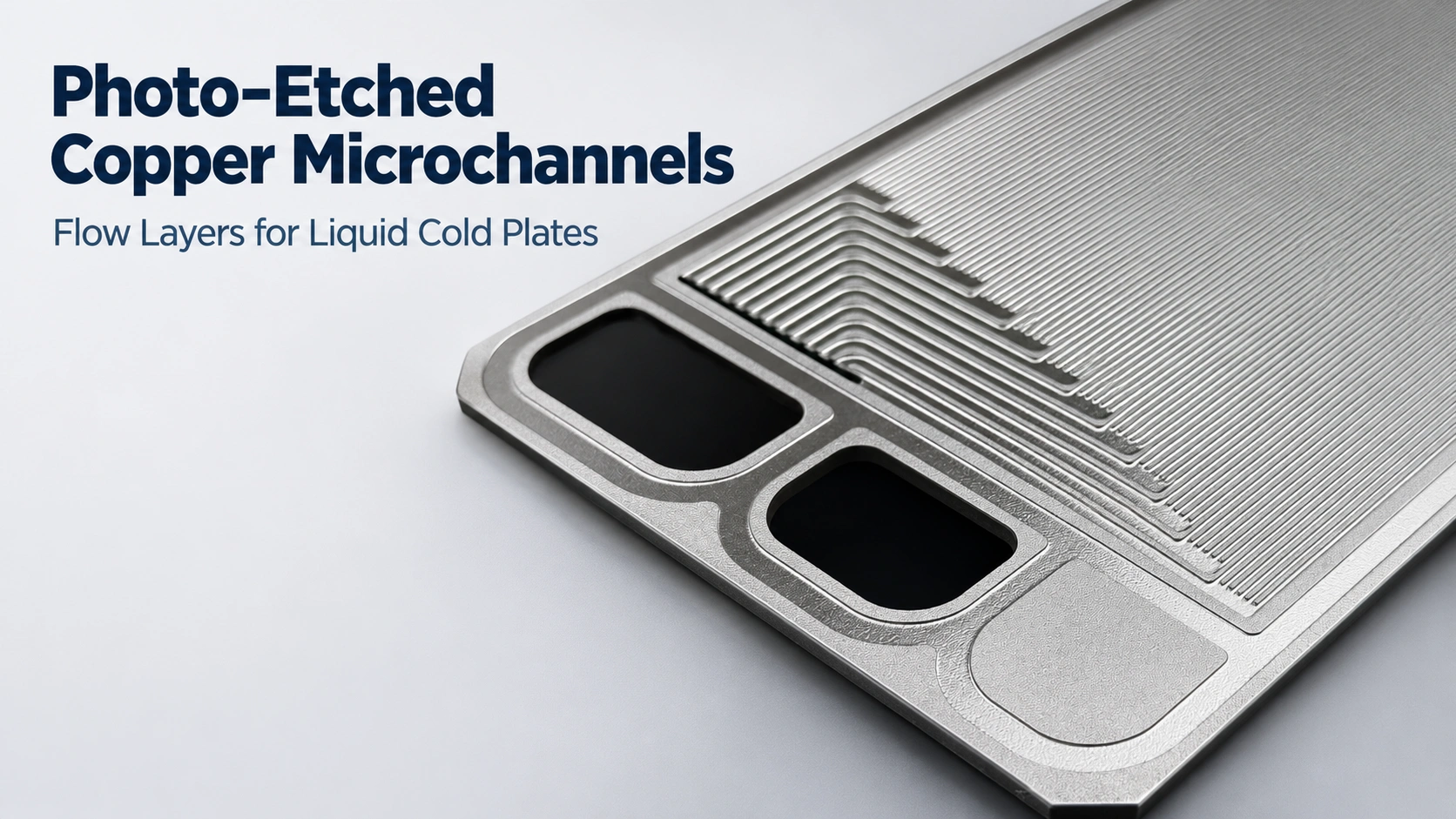
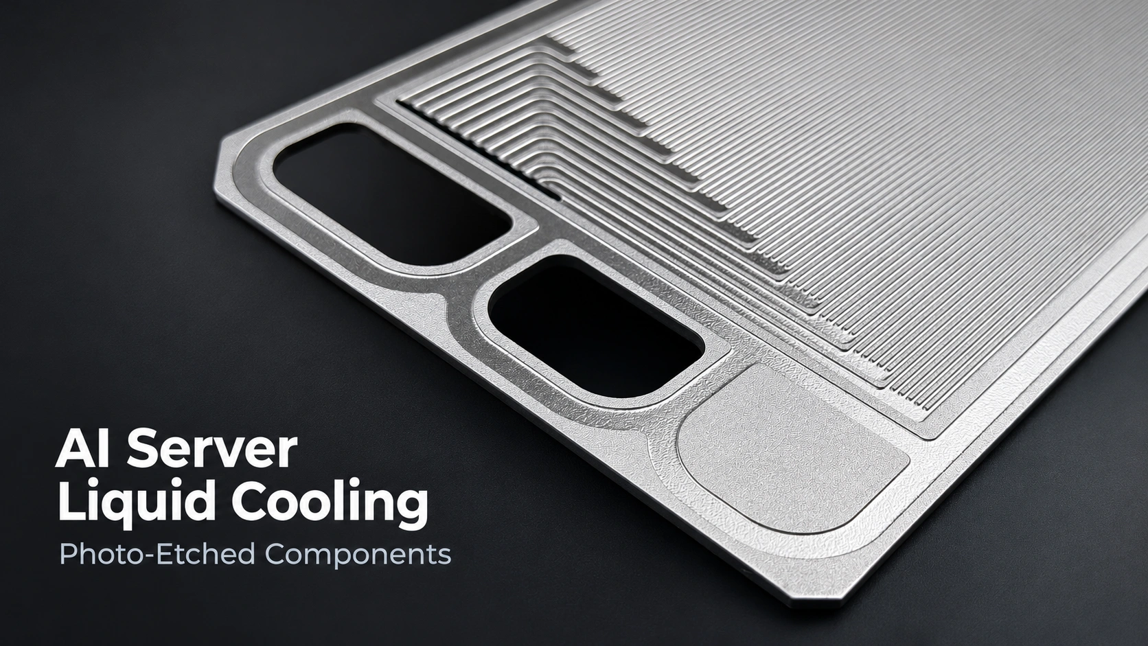
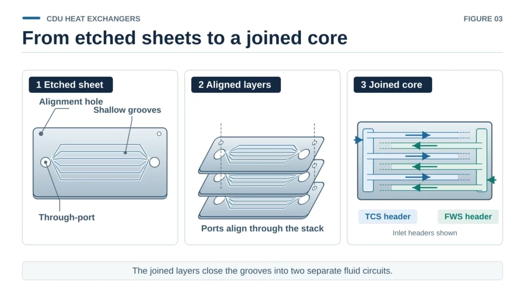
An etched microchannel core starts with flat sheets. Photochemical etching for microchannel heat exchangers can form shallow channels, through-ports, and alignment holes. The sheets are then aligned, stacked, and joined to enclose the passages. A printed circuit heat exchanger (PCHE) is one example that uses diffusion bonding to join the layers. Headers distribute fluid into each circuit and collect it at the outlet.
Which Design Constraints Justify a Custom Core?
Identify the requirement a catalog layout leaves unresolved. If the ports need to match existing piping, give the supplier their centerlines and the space available around them. Ask for a layout showing where the headers sit and how they feed the channels. That drawing gives you a way to verify fit before committing to a prototype.
Once the layout fits, check the passage shape the coolant will actually see. Diffusion bonding can change the cross-section of an etched channel, so ask whether the supplier’s heat transfer and pressure-drop calculations use the joined geometry. For a new stack, request measurements from a representative joined sample and a flow test on the finished core.
How to Compare Both Designs at the Same CDU Duty
Fix the Load, Fluids, and Approach Temperature
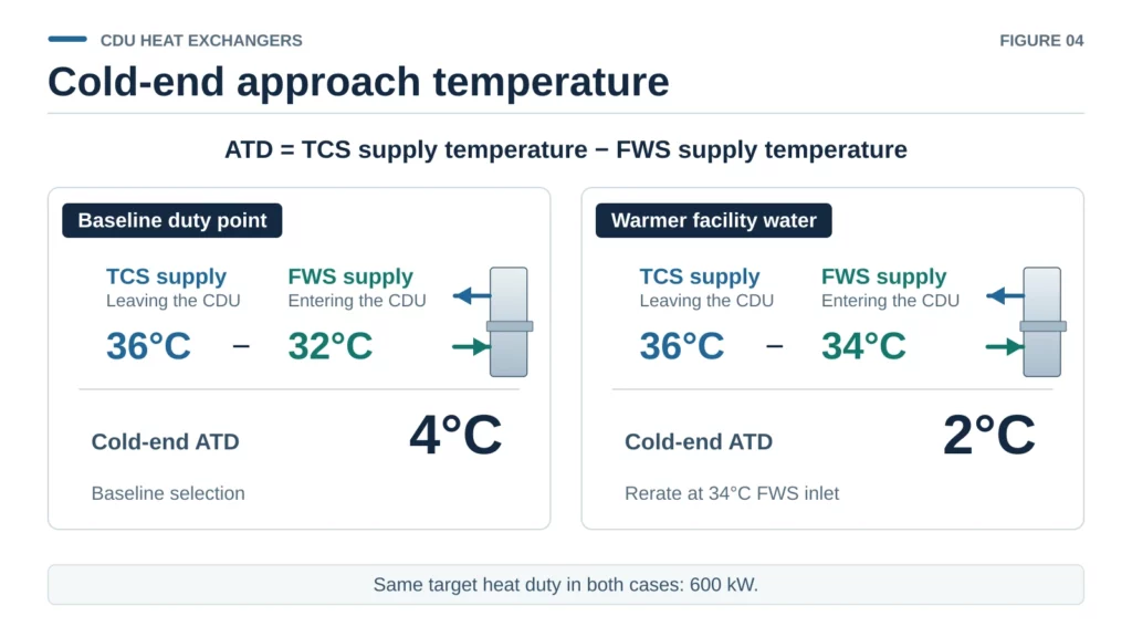
Put the required heat duty, fluids and concentrations, flow rates, and design temperatures for both circuits on one duty sheet. Give each supplier the warmest FWS supply temperature the CDU must handle and the corresponding TCS supply target. Those temperatures define the cold-end approach temperature difference (ATD).
Cold-end ATD = TCS supply temperature − FWS supply temperature
The Vertiv CoolChip CDU 600 selection example, Figure 4.3 uses water in both loops, with a 14.5°C difference between TCS supply and return. The example calls for 600 kW of heat transfer with FWS entering at 32°C and TCS supply set to 36°C. The temperature difference is 4°C. The guide gives a minimum FWS flow of 650 L/min for that operating point.
Now suppose the facility water arrives at 34°C and the racks still need 36°C coolant. The required approach falls to 2°C, so the core has a smaller temperature difference to drive heat transfer at the cold end. Ask both suppliers to rerate at the warmer inlet while holding the 600 kW duty target. Their updated selections give you the required flow. At that flow, check the pressure drop against each loop’s pressure budget.
Compare Pressure Drop at the Correct Measurement Points
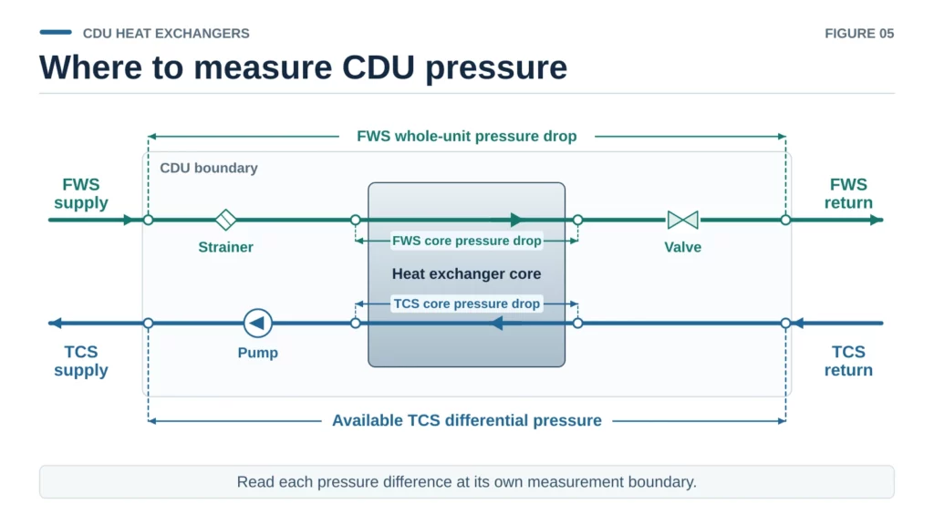
Start with the pressure-drop curve from inlet to outlet on each side of the core. Read each curve at the required flow and fluid temperature. The CDU also contains components such as valves and strainers. To account for the full unit, check the pressure at its supply and return connections.
- On the facility side, check the pressure drop across the CDU. This is the resistance the facility loop must overcome between the unit’s FWS connections. Confirm which valves and strainers the rating includes and the condition of the strainer.
- On the technology side, check the differential pressure available to the rack loop. Measure the difference between the CDU’s TCS supply and return at the stated flow and pump setting. The pressure drop through the rack piping, manifolds, and cold plates must fit within that budget.
Check the Installed Space and Service Requirements
Check installed fit with the connections and valves in place. Allow clearance for filter service and core removal. Give both suppliers the same water-quality and filtration requirements so you can compare their cleaning or replacement plans on the same basis.
| Requirement to check | Brazed plate option | Custom etched core option |
|---|---|---|
| Heat duty at the specified fluids, temperatures, flows, and ATD | Model-specific selection sheet | Rating or test results for the proposed core at the same conditions |
| Pressure drop on both sides at the required flow | Core loss curves with the fluids and measurement points identified | Curves using the same fluids and measurement points, with the tested core identified |
| Working pressure, temperature limits, pressure difference between circuits, and wetted materials | Model limits and materials, including any filler in contact with the fluid | Joined-core limits, materials, joining method, and qualification records |
| Installed space, ports, filtration, and service access | Installation drawing and maintenance instructions | Finished-core drawing and service plan |
What Must the Finished Heat Exchanger Prove?
Inspect the Plates Before Joining
For a custom etched stack, inspect the parts while the grooves and joining surfaces are accessible. If a groove has tapered sides, specify the plane at which its width is measured. Check the metal remaining under the groove, the flat area available for joining, and the reference features used to align the ports. Tie the etched plate inspection results to the drawing revision and material lot.
Test the Joined Core and Verify the CDU
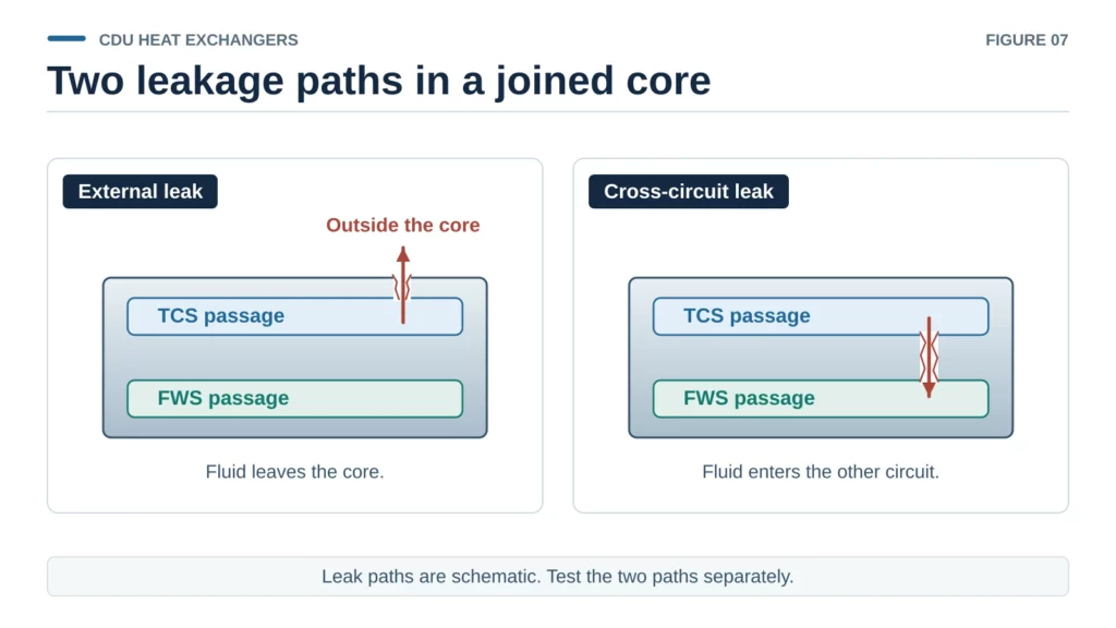
Joining turns the open grooves into closed circuits, so the next checks are flow continuity, pressure containment, and leakage. Check for leakage to the outside of the core and between the two circuits. Agree with the core integrator on the test conditions and acceptance limits for each path.
After the core is installed, return to the duty sheet. Verify the heat load, approach temperature, and hydraulic performance at the CDU connections. This is where you confirm that the completed unit can meet the requirements used to select the core.
| Stage | Acceptance question | Evidence to keep |
|---|---|---|
| Etched plate supplier | Do the plate features meet the drawing and joining requirements? | Material traceability and dimensional inspection |
| Core integrator | Can each circuit pass flow and hold pressure while remaining isolated? | Flow check, pressure and leak test records, and tested core ID |
| CDU manufacturer | Does the assembled unit meet the design point at its connections? | Heat duty, ATD, FWS pressure drop, and available TCS differential pressure |
What to Send for an Etched Flow-Plate DFM Review
Use the plate acceptance criteria to prepare the drawing for a design-for-manufacturability (DFM) review. Send a 2D drawing and CAD file at the same revision. Identify the alloy, material condition, and stock thickness. Mark which features are recessed and which go through the sheet. Specify groove width and depth, the minimum remaining wall under the groove, and the tolerances that control port alignment. Include the intended joining method, surface requirements, and sample quantity.
TMNetch Case Study — Etching Fine Flow Features on Large Plates
In a TMNetch patterned flow-plate project, the plates had fine flow features and larger structural cuts. The main materials recorded were 316 stainless steel and titanium. TMNetch used chemical etching for the fine flow features and laser cutting for the larger cuts.
Apply the same drawing review to a CDU flow plate. Mark the fine channels and large through-cuts, then identify the flat areas that have to stay continuous for joining. Agree on which surfaces to preserve before the plate goes into production. For a flow plate, distribution layer, or spacer, send your marked-up drawing to TMNetch for a photochemical etching feasibility review.
Frequently Asked Questions
Can photo-etched microchannel plates be brazed?
Yes. Photo-etched plates can be stacked and vacuum brazed to enclose the channels. For a CDU, check that the alloy and filler suit the fluids and operating temperatures, then verify the joint on the assembled core.
Can an etched core replace a brazed plate heat exchanger in an existing CDU?
It can if the ports, installed dimensions, wetted materials, and pressure limits suit the existing unit. Use the original cooling duty and approach temperature to rate the replacement. Then check the flow and pressure drop again at the CDU connections after integration.
Conclusion
A catalog brazed plate heat exchanger is a practical choice when it fits the installation and meets the required heat duty, approach temperature, and pressure-drop limits on both sides. Evaluate an etched microchannel core when space, port locations, or flow paths call for a custom layout. Rate both options at the same duty point, then verify the selected design at the assembled CDU’s connections.
For a flow plate, distribution layer, or spacer, request a photochemical etching feasibility review from TMNetch. Include your marked-up drawing, alloy, sheet thickness, channel dimensions, and joining requirements.