
Manufacturing an alkaline electrolyzer involves linked operations: separator and electrode preparation, frame and plate processing, gasket cutting, welding, stack assembly, and controlled compression. Each operation affects dimensions, sealing, electrical contact, gas separation, and final stack reliability. Equipment selection must therefore follow the product drawing and its critical interfaces—not machine speed alone.
This guide follows alkaline electrolyzer manufacturing from incoming materials to stack release. It identifies equipment, critical-to-quality parameters, or CTQs, and common defects. Verify every process and acceptance limit against the released OEM stack architecture.
Key Takeaways
- Alkaline electrolyzer manufacturing combines material preparation, cutting, welding, alignment, compression, and inspection.
- Separator accuracy and electrode geometry need component-specific controls; they are not ordinary sheet-metal parts.
- Cutting accuracy does not guarantee part accuracy if the material wrinkles, curls, or moves in the fixture.
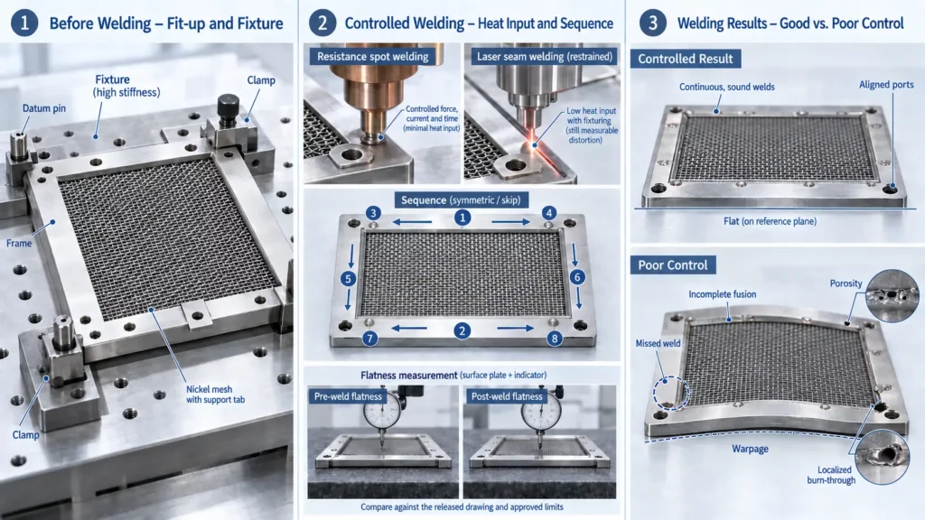
- Welding affects flatness, alignment, electrical continuity, and leak-related interfaces.
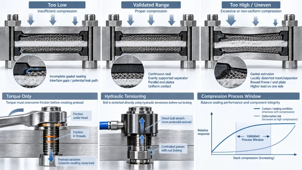
- Stack assembly requires controlled alignment and preload, not simply tightened bolts.
- Automation becomes more valuable as volume, part size, traceability, and repeatability requirements increase.
- Quality control must continue from incoming inspection through stack leak, electrical, flow, and functional testing.
Alkaline Electrolyzer Manufacturing Process at a Glance
An alkaline water electrolyzer, or AWE, should be manufactured as one controlled chain:
Requirements → Incoming inspection → Separator preparation → Electrode preparation → Frame and plate processing → Gasket cutting → Welding → Component inspection → Stack assembly → Compression → End-of-line testing
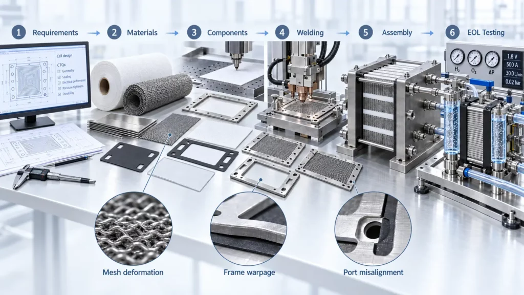
The stages are connected. A distorted electrode can change the electrode–separator interface. A warped frame can shift the gasket load. A misplaced separator or blocked port may only become visible during leak, flow, or performance testing.
For this reason, inspection should occur near the process that creates each risk. Finding a frame error before welding costs less than diagnosing it after a full stack has been compressed.
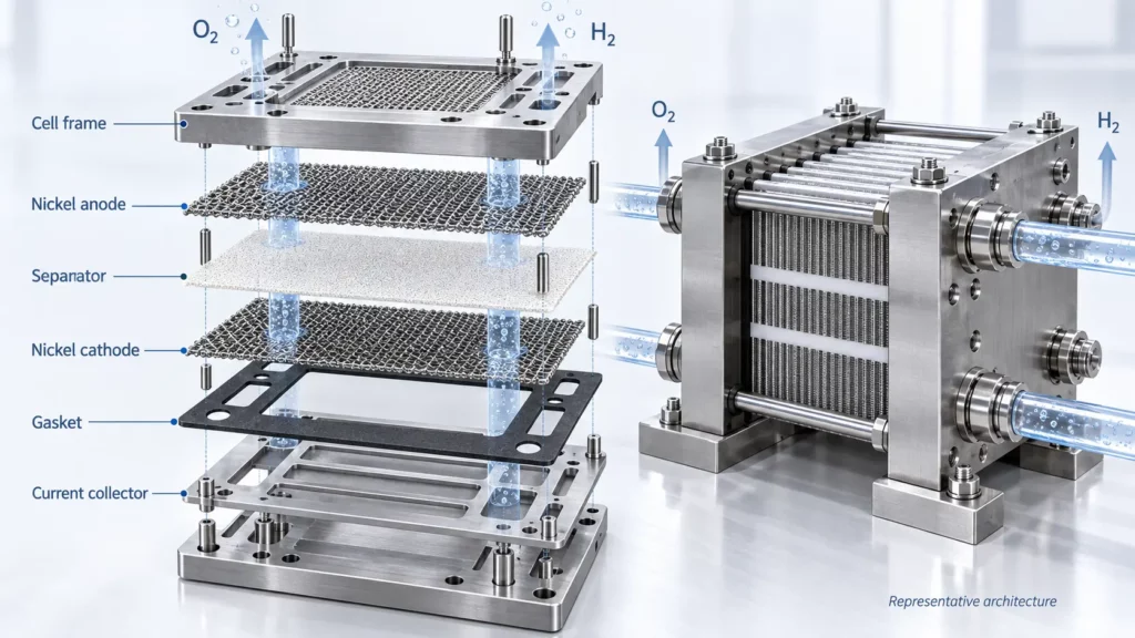
Main Components in an Alkaline Electrolyzer Stack
Components vary with monopolar, bipolar, finite-gap, zero-gap, and OEM-specific architectures. Confirm every name and function against the stack drawing before planning tooling.
Electrodes
Electrodes may use nickel mesh, nickel foam, perforated metal, expanded structures, or other specified substrates. Geometry, surface treatment, catalytic coating, electrical connection, and the separator gap determine their manufacturing controls. The U.S. Department of Energy’s liquid alkaline electrolysis workshop identifies electrodes and diaphragms as major AWE development areas.
Diaphragm or separator
The separator limits product-gas mixing while allowing ionic transport through the electrolyte. It must withstand handling, compression, temperature, and chemical exposure. PPS cloth is not a universal specification; reinforced composites such as Zirfon-type structures are also used. A peer-reviewed separator review explains why pore structure, thickness, stability, wetting, resistance, and gas separation require joint evaluation.
Cell frames and plates
Frames and plates support and locate components, form flow passages, and may conduct current. Terms such as cell frame, pole frame, bipolar plate, and current collector are architecture-dependent. For thin metal components that require precise openings, repeated patterns, flow features, or complex flat geometries, chemical etching can be evaluated alongside stamping, laser cutting, and machining.
Gaskets and compression hardware
Gaskets contain electrolyte, separate flow paths, and define local compression. End plates and tie rods transfer load; their stiffness and variation affect the full stack.
Define Manufacturing Requirements Before Selecting Equipment
Start with the stack specification. Then select processes and machines that can control the required outputs.
| Requirement group | Define before equipment selection |
|---|---|
| Stack geometry | Active area, frame size, cell count, final stack height |
| Component geometry | Separator profile, electrode location, gasket openings, ports, grooves |
| Operating conditions | Electrolyte, temperature, pressure, differential pressure, current density |
| Production | Prototype quantity, annual volume, changeover frequency, target yield |
| Quality system | Inspection points, data retention, lot traceability, nonconformance control |
Specify required part outputs, not only axis repeatability. Flexible mesh can move despite accurate machine positioning. Fixtures, material behavior, thermal input, and measurement capability determine final accuracy.
Select equipment backward from the component CTQs. Do not select a machine first and force the product into its process window.
Incoming Materials and Preparation
Verify material specification, certificate or batch record, thickness, flatness, surface condition, and identification before production.
Apply component-specific checks:
- Inspect separators for creases, tears, blocked areas, contamination, and handling damage.
- Inspect mesh or foam for curling, crushed zones, broken strands, or unstable edges.
- Check frame and plate stock for flatness, surface condition, and coating or plating status.
- Check gasket-sheet consistency, cleanliness, storage, and shelf life where applicable.
Define sampling and quarantine rules. Once a defective lot reaches welding or assembly, root-cause isolation becomes harder.
Diaphragm Cutting and Preparation
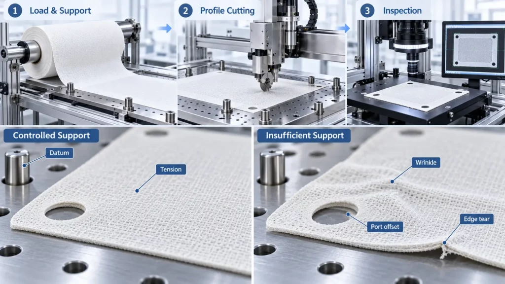
Separator preparation covers loading, tension control, datum location, profile and port cutting, protected handling, and inspection. The method must match the approved diaphragm structure.
Automatic or semi-automatic cutters can improve repeatability. Fixtures and cutting methods must prevent wrinkles, heat damage, tearing, contamination, and pore blockage. Do not claim finished-part accuracy from machine positioning data alone.
Key separator CTQs include:
- Overall profile and port location
- Edge condition and absence of tears
- Flatness or wrinkle control
- Surface cleanliness
- Correct material orientation, if the design is side-specific
Dimensional errors affect sealing or manifold alignment; handling damage can create an unwanted gas path. Inspect with an approved visual, dimensional, or optical method.
Electrode and Nickel Mesh Manufacturing
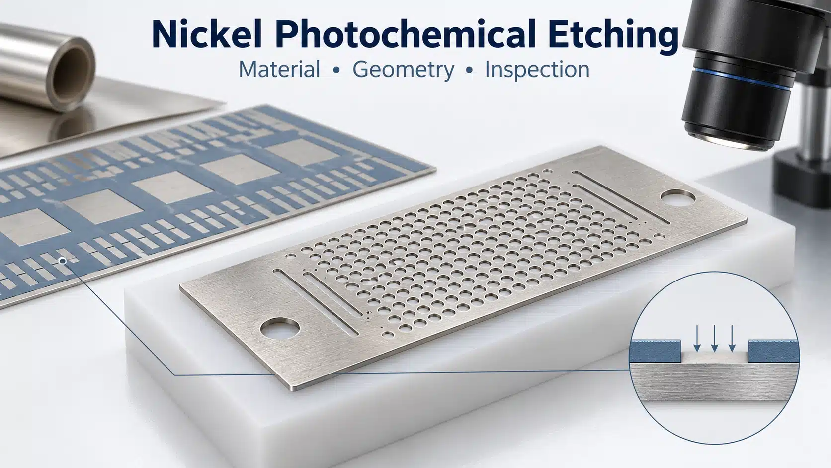
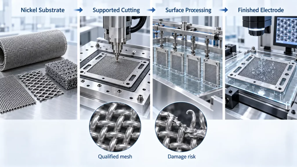
Nickel mesh, nickel foam, expanded metal, or another specified substrate may require profile and opening cuts. Flexible materials need flattening plates, vacuum support, clamps, or dedicated nests. For thin nickel sheets or mesh structures that require fine openings, repeated patterns, or complex profiles, photochemical etching can also be evaluated as a precision manufacturing route.
Inspect profile, opening position, flatness, broken strands, sharp projections, and local deformation. Correct outside dimensions do not prove an undamaged active area.
Cutting nickel mesh does not create a finished electrode. Later steps may include cleaning, activation, coating, heat treatment, or joining. DOE’s cell-level AWE review treats structure, conductivity, wettability, permeability, activity, and bubble behavior as coupled requirements.
The mesh cutter controls geometry; it does not prove catalytic loading, surface activity, or electrochemical performance.
Cell Frame and Plate Manufacturing
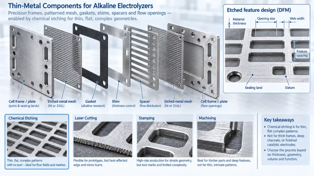
Frame and plate processing may include chemical etching, laser cutting, machining, stamping, groove formation, drilling, plating, and welding. Select the manufacturing route according to material, thickness, feature geometry, tolerance, architecture, design maturity, and production volume.
Control the features that position or seal other components:
- Outer profile and frame opening
- Electrolyte and gas ports
- Flow grooves or distribution features
- Electrode and separator datums
- Sealing surfaces
- Flatness before and after joining
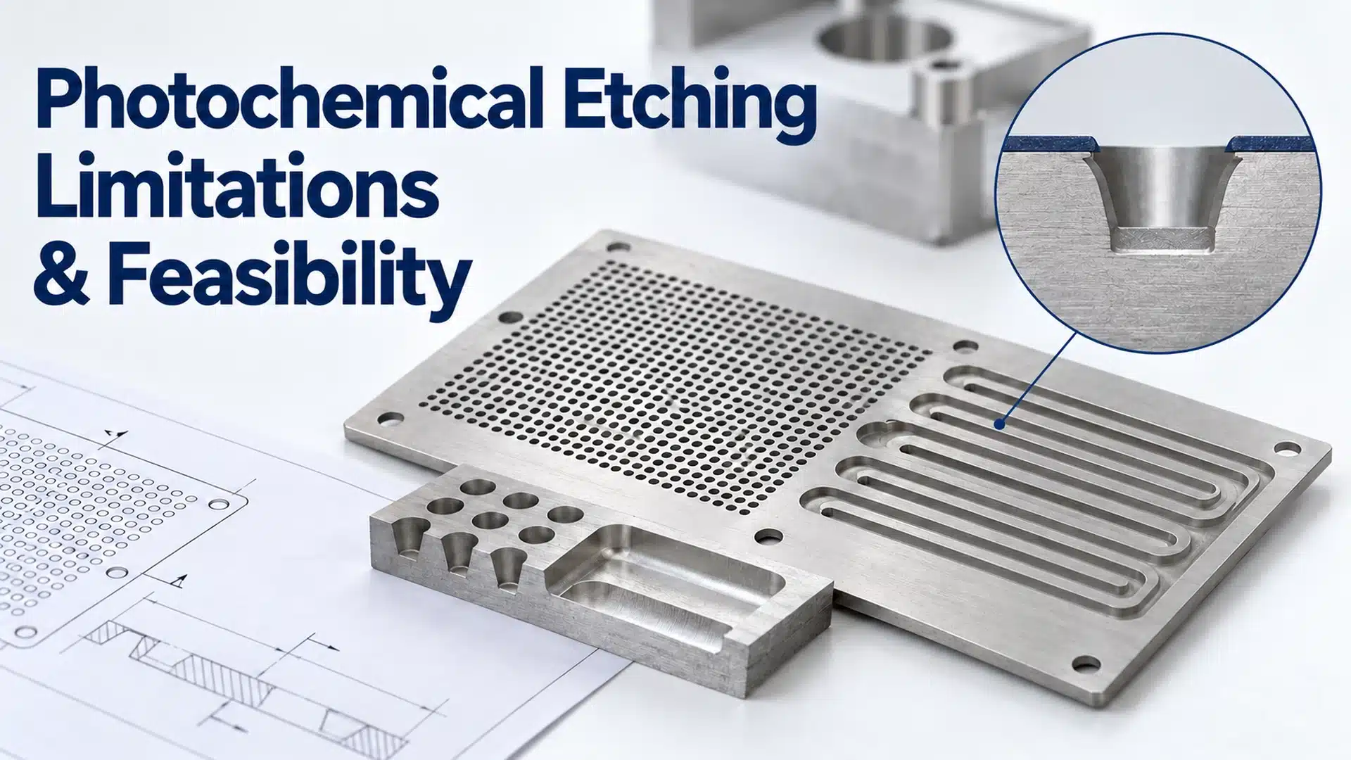
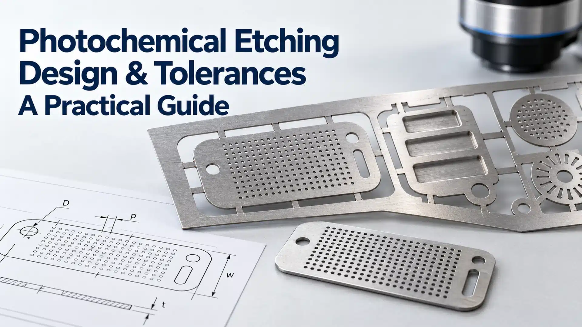
When these features are produced in thin metal by etching, minimum opening size, web width, feature spacing, dimensional tolerance, and material thickness must remain within the process window. Engineers can review the applicable photochemical etching tolerances and design limits before releasing a production drawing.
Pole-frame cutting equipment can combine CAD profiles with dedicated fixtures. Inspect groove location, port continuity, sealing lands, and flatness; machine coordinates alone are insufficient.
Remove oil, oxide, loose particles, or damaged plating as required before the next operation.
Gasket Manufacturing
Gasket thickness controls the compressed interface. Profile and port position keep electrolyte and gas paths separated. For thin metallic sealing, spacing, or tolerance-control components, precision etched metal gaskets and shims can be manufactured with custom profiles, ports, slots, and alignment features.
The process covers sheet preparation, nesting, cutting, cleaning, identification, and protected storage. Control flexible-sheet movement during cutting.
Inspect thickness, dimensions, port position, edges, surface, and identity. Reject torn, contaminated, or deformed parts to approved criteria. Define sealing dimensions and datums on the drawing.
Welding Equipment for Alkaline Electrolyzer Components
Welding may join plates, frames, mesh, supports, and current-carrying interfaces. Select the method by joint design, material, thickness, electrical duty, allowable distortion, and containment function.
Welding methods and equipment
Resistance spot welding can suit discrete mesh connections. Laser welding supports controlled seams and automated paths. No method is automatically superior: even low nominal heat input can distort a thin frame when sequence, fit-up, or fixturing is poor.
Welding CTQs
Control fixture position, fit-up, cleanliness, heat input, path, fusion, spacing, and sequence. Common defects include incomplete fusion, porosity, burn-through, missed welds, spatter, movement, and post-weld warpage.
Welding inspection
Check weld location, continuity, surface condition, frame geometry, and post-weld flatness. Add leak or other non-destructive tests when required by the joint function.
ISO 17637:2016 covers visual testing of fusion welds. ISO 13919-1:2019 provides imperfection quality levels for applicable laser-welded steel, nickel, titanium, and alloy joints. Neither replaces product-specific validation.
Handling Equipment for Large Components
Large frames may require lifting platforms, cranes, spreaders, flipping tables, and guided transfer systems. These are process-control tools, not only labor-saving devices.
Handling equipment should:
- Support the component without permanent deformation
- Maintain the selected datum during loading or flipping
- Protect sealing and coated surfaces
- Reduce manual contact and contamination
- Keep operators outside pinch, drop, and crush hazards
Review load rating, center of gravity, support points, rotation envelope, fixture stiffness, emergency stops, and safe access. Validate handling with production geometry.
Alkaline Electrolyzer Stack Assembly
Stack assembly places repeated cells between end structures. The OEM-defined sequence may include frames, electrodes, separators, gaskets, plates, collectors, and insulation.
Control separator-to-electrode position, gasket overlap, manifold continuity, and cell-to-cell datum accumulation. Pins, nests, templates, or vision systems must locate parts without damage.
Remove metal debris, oil, dust, fibers, and packaging residue. Define part presentation, glove rules, tool control, cleaning verification, and rejection criteria.
Assembly fixtures should maintain geometry, verify cell count and orientation, and support traceability. Do not correct accumulated alignment by eye.
Compression and Hydraulic Bolt Tensioning
Compression must create sealing and contact without damaging the stack. Low load risks leakage and unstable contact; excess load can deform seals, separators, electrodes, or frames.
Bolt torque is not clamping force. Threads, lubrication, friction, tool accuracy, tightening sequence, end-plate stiffness, and component stack-up change preload.
Hydraulic tensioning can control bolt preload more directly than torque-only tightening. A validated system may use controlled passes, multiple tensioners, stack-height checks, and feedback. Control uniformity as well as total load.
Do not copy supplier example values into production drawings. Validate the range for the actual gasket system, component architecture, stack size, stiffness, pressure, temperature, and load history.
Quality Control Across the Manufacturing Line
The quality plan should connect each process to a CTQ, failure mode, and inspection method.
| Stage | Primary CTQ | Main failure risk | Inspection approach |
|---|---|---|---|
| Separator cutting | Profile, ports, edge condition | Misalignment or gas-separation risk | Visual and dimensional |
| Electrode preparation | Geometry, flatness, surface | Uneven interface or electrical path | Optical, dimensional, surface |
| Frame processing | Ports, grooves, flatness | Flow, sealing, or alignment error | Profile, CMM, flatness |
| Gasket cutting | Thickness, profile, openings | Leakage or compression variation | Thickness and optical |
| Welding | Location, integrity, distortion | Structural, electrical, or leak risk | Visual, dimensional, specified NDT |
| Assembly | Sequence, orientation, alignment | Blocked path or interface mismatch | Fixture, vision, build record |
| Compression | Preload, stack height, flatness | Leakage or contact variation | Load, displacement, dimensional |
| Final stack | Leakage, flow, electrical integrity | Unsafe or unstable operation | End-of-line test plan |
Record the method, sampling, instrument capability, limits, and reaction plan. A CTQ without a measurement method is not a production control.
For outsourced thin-metal components, the same principle applies before supplier release: the drawing, material, thickness, critical dimensions, inspection method, and production quantity should be reviewed together. TMNetch provides precision chemical etching manufacturing for custom thin-metal components used across energy, electronics, thermal-management, and other engineering applications.
End-of-Line Testing Before Release
End-of-line, or EOL, testing verifies the assembled stack against its approved architecture and operating envelope.
Leak and pressure testing
Check external leakage and unintended communication between fluid or gas circuits. Define test media, pressure, temperature, dwell time, leakage limit, and safety controls in the validated procedure.
Electrical and flow checks
Check continuity, insulation, resistance, and unexpected shorts as required. Verify that ports, manifolds, and internal paths are open and correctly connected.
Commissioning or performance checks
Where applicable, record voltage, current, gas output or composition, temperature, pressure, and cell behavior. Compare abnormal results with component, assembly, and test-system records.
ISO 22734-1:2025 covers safety requirements for water-electrolysis hydrogen generators. Stack EOL results can support conformity work, but do not certify the complete generator.
Common Manufacturing Defects and Causes
| Defect | Likely cause | Main risk | First check |
|---|---|---|---|
| Separator misalignment | Cutting, datum, or assembly error | Sealing or gas-separation problem | Profile and assembly position |
| Mesh deformation | Cutting or handling load | Uneven electrode geometry | Flatness and support method |
| Frame warpage | Welding heat or weak fixture | Seal and alignment variation | Pre/post-weld flatness |
| Incomplete weld | Fit-up, contamination, or parameters | Structural or electrical failure | Weld path and joint condition |
| Gasket offset | Cutting or assembly error | Electrolyte leakage | Port and sealing-land overlap |
| Uneven compression | Preload or end-plate variation | Leakage and contact variation | Bolt load, stack height, flatness |
| Blocked flow path | Part error or contamination | Restricted circulation | Port and manifold flow test |
| Particle contamination | Weak cleaning control | Local damage or short circuit | Assembly environment and records |
Confirm each defect with measurements, then trace it to material, tooling, process, assembly, or test conditions.
How Much Automation Does an Alkaline Electrolyzer Line Need?
Match automation to design maturity and production demand.
| Production mode | Best fit | Main advantage | Main limitation |
|---|---|---|---|
| Manual or prototype | Low volume, frequent design changes | Flexible learning and rework | Higher operator variation |
| Semi-automated | Repeated products, moderate volume | Automates critical cutting or welding | Manual transfers can remain variable |
| Automated line | Stable design, higher volume | Throughput, repeatability, data capture | Higher tooling and integration commitment |
Target the dominant variation or bottleneck. Robots do not correct unstable joints, and faster cutters do not stop flexible materials moving. Stabilize the process before automating it.
The DOE manufacturing program identifies automation, design for processability, scale-up, and advanced quality control as electrolyzer-manufacturing priorities. This does not mean every station needs full automation.
Equipment Selection Checklist
Define these inputs before requesting an alkaline electrolyzer production line.
Product requirements
- What are the component size, material, thickness, and mass?
- Which tolerances and surfaces affect sealing, alignment, or electrical contact?
- Is the material flexible, porous, coated, or sensitive to heat?
Process requirements
- Which operation creates the CTQ: cutting, forming, welding, handling, or compression?
- What fixtures, datums, and error-proofing are required?
- How will deformation and contamination be controlled?
For outsourced thin-metal components, manufacturing-route selection should also compare feature complexity, material thickness, tolerance, tooling cost, prototype volume, and expected design revisions. Chemical etching services are particularly relevant when flat metal parts require complex openings or repeated geometries without mechanical cutting forces.
Production and quality requirements
- What are the volume, product mix, cycle time, and target yield?
- Which inspections must be inline, sampled, or performed at EOL?
- What process data, alarms, and rework records must be retained?
Factory requirements
- What space, utilities, ventilation, guarding, and material flow are available?
- How will large parts be loaded, flipped, transferred, and stored safely?
- Can maintenance and calibration be completed without disrupting critical controls?
Where Precision Metal Manufacturing Fits
Precision metal manufacturing may support selected AWE components without covering the complete electrolyzer. Candidates include thin mesh, patterned metal parts, shims, spacers, flow openings, and selected support or plate features.
Chemical etching is worth evaluating for thin, flat parts with complex openings, repeated patterns, low mechanical distortion, or frequent CAD revision. It is not suitable for every thick frame, deep-formed part, or finished catalytic electrode.
Review custom etched metal mesh or stainless steel etching for suitable thin parts. Submit the drawing, grade, thickness, CTQs, quantity, surface requirements, and function. DFM should confirm whether etching, laser cutting, stamping, machining, or a combined route fits best.
Frequently Asked Questions
What equipment is used to manufacture alkaline electrolyzers?
Typical equipment includes component cutters, welders, handling systems, assembly fixtures, bolt tensioners, inspection equipment, and EOL stands. Select them for the architecture, part size, volume, and CTQs.
How are alkaline electrolyzer electrodes manufactured?
The substrate is cut and inspected, then may be cleaned, activated, coated, heat-treated, or joined. Cutting mesh alone does not create a finished electrode.
How is the separator cut and installed?
The separator is supported, cut, inspected, and protected. Assembly fixtures align it with the electrode, gasket, and manifold. The method must match the approved material and architecture.
Why is welding quality important in an alkaline electrolyzer stack?
Welding affects integrity, electrical continuity, flatness, and feature position. Control heat input, fit-up, fixtures, sequence, and inspection together.
How is an alkaline electrolyzer stack compressed?
Repeated cells are aligned and loaded through bolts, tie rods, or another validated system. Check stack height, flatness, and preload uniformity—not torque alone.
What tests are performed before stack release?
EOL testing may cover leakage, pressure integrity, electrical checks, flow, and controlled operation. Conditions and limits must come from the released design.
Conclusion
Alkaline electrolyzer manufacturing links separator geometry, electrode condition, frame flatness, weld quality, gasket position, alignment, and compression.
Use one logic: Requirements → Components → Preparation → Cutting → Welding → Assembly → Compression → Inspection → Release. For every operation, define the equipment, CTQ, failure mode, and inspection method before production.
If your alkaline electrolyzer project includes thin metal plates, patterned mesh, shims, spacers, flow openings, or other precision flat components, submit your component drawing to TMNetch for a manufacturing review. Include the material, thickness, critical dimensions, tolerance requirements, quantity, and surface or joining requirements.