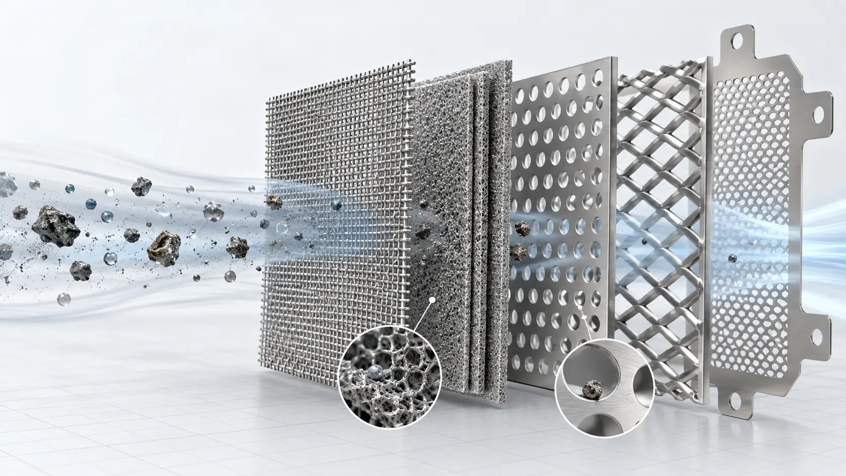

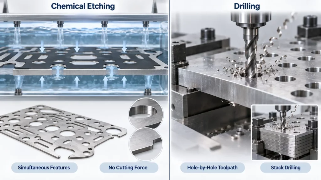
Heat exchanger baffle plates often contain large arrays of tube holes or flow openings. Both chemical etching and drilling can create these features, but they do so by very different material-removal mechanisms. Photochemical machining removes exposed metal by controlled chemical dissolution through a photoresist pattern, while conventional drilling removes material mechanically with a cutting tool. These process differences affect hole geometry, plate thickness capability, burr formation, structural suitability, inspection, and production economics.
For that reason, the first question should not be “Which process can make the holes?” It should be “What must the finished baffle do?” EPRI notes that baffle plates in shell-and-tube heat exchangers support tubes and direct shell-side flow, while baffle spacing also affects pressure drop, heat-transfer performance, and tube vibration. A manufacturing method is useful only if the finished plate can meet those functional requirements.
Key Takeaway: Chemical etching is generally more attractive for thin, flat plates with dense or complex two-dimensional hole patterns. Drilling is generally more natural for thicker structural baffles that need cylindrical holes, defined hole-wall geometry, or greater stiffness. This is an engineering screening rule, not a universal process limit; final selection should be based on the actual drawing, material, thickness, support function, and inspection requirements.
Etched Baffle Plates vs Drilled Baffle Plates: Quick Comparison
| Factor | Chemical Etching | Drilling | Engineering Implication |
|---|---|---|---|
| Plate thickness | Best suited to relatively thin sheet | Handles substantially thicker sections | Thickness is often the first filter |
| Hole quantity | Many exposed features are etched in the same process step | Each hole requires a drilling path, although plates can be stack-drilled | Dense arrays strengthen the case for etching |
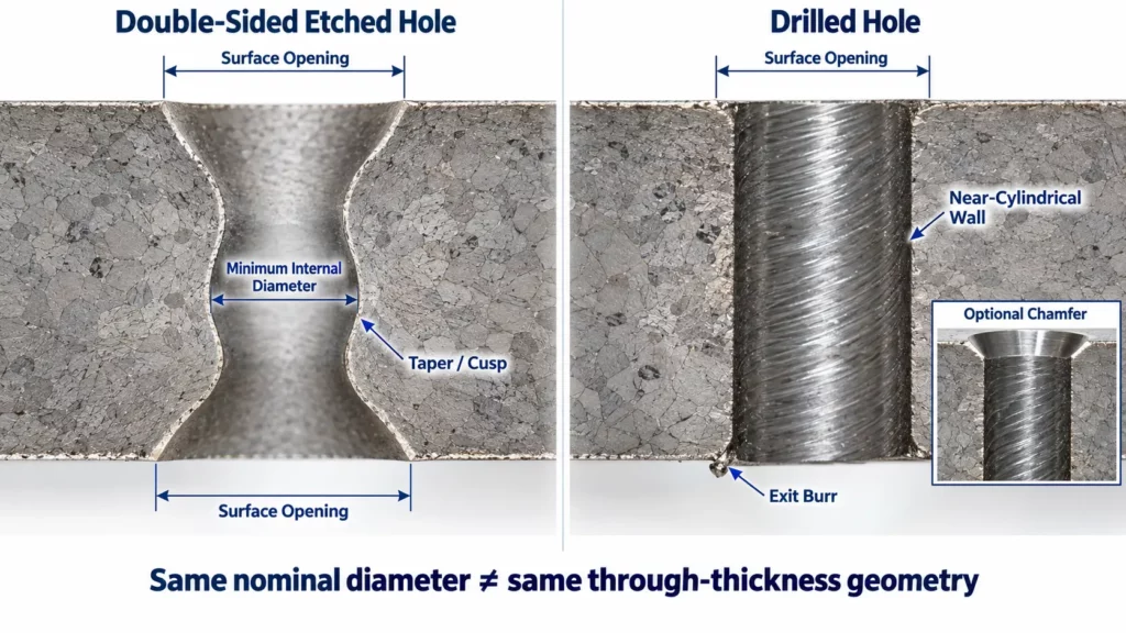
| Hole geometry | Taper, undercut, or a cusped profile can occur | Near-cylindrical holes are easier to define | Tube-contact holes may favor drilling |
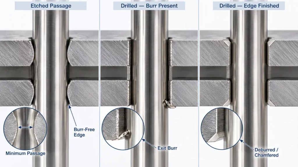
| Burrs | No mechanical cutting burr | Entry and exit burrs can form | Deburring may be required before assembly |
| Complex patterns | Round holes, slots, and external profiles can be patterned together | Irregular features may require added machining | Complex 2D geometry favors etching |
| Structural thickness | Thin-sheet applications are the natural process space | Common for structural baffle plates | Structural duty can override feature complexity |
| Production economics | Driven by panel layout, thickness, material, process and inspection | Driven by hole count, cycle time, stack size, tool life and deburring | Compare quotations from the same drawing |
Start With the Baffle Function, Not the Manufacturing Process
A thin flow-distribution plate with many slots, apertures, or irregular openings is close to the natural application space of photochemical machining. Published PCM research describes the process as suitable for intricate thin-walled components and complex micro-geometries because the shape is defined by patterned photoresist rather than a mechanical cutting path.
A tube-support baffle is different. If the plate must control unsupported tube span, resist deformation, and maintain tube position, stiffness and hole-wall behavior can matter more than pattern complexity.
This distinction is important because EPRI identifies both tube support and shell-side flow control as baffle functions. It also connects baffle spacing with pressure drop, heat-transfer efficiency, and tube vibration. These relationships are part of the broader heat exchanger design and operating principles that should be understood before selecting the baffle manufacturing route.
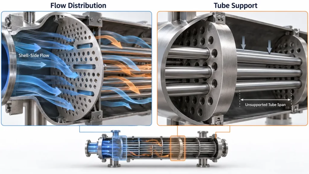
Plate Thickness Is Usually the First Screening Parameter
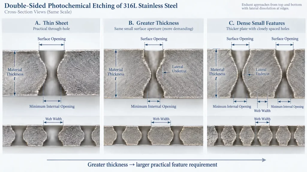
In photochemical machining, plate thickness and minimum feature size are related because the etchant removes metal through the thickness while also attacking laterally. A recent review of PCM identifies edge deviation and undercut as important responses affected by etchant concentration, temperature, etching time, agitation, and photoresist conditions.
For early design-for-manufacturability screening, Photofabrication Engineering publishes a practical rule that holes in material at or above 0.127 mm thickness should generally be at least 110% of the metal thickness. Its example table increases the suggested minimum hole diameter to roughly 1.2×, 1.4×, 1.6×, and 1.8× material thickness as the sheet becomes thicker. The same guide suggests a minimum metal web of about 1.2× thickness for dense hole patterns in material at or above 0.127 mm.
These figures should be treated as DFM guidance rather than a universal standard. Actual limits depend on alloy, thickness, pattern density, photoresist compensation, etchant conditions, and the tolerance required. Engineers can review the applicable photochemical etching tolerances and design limits before finalizing a baffle plate drawing.
Drilling does not have the same lateral-etch mechanism. Industrial tooling guidance for heat-exchanger baffles specifically covers small- and large-diameter holes as well as stacked drilling of multiple plates. This makes drilling a more natural route as the design moves toward thicker conventional tube-support baffles.
Hole Geometry: Cylindrical Drilled Holes vs Etched Profiles
An etched through-hole should not automatically be treated as a perfect cylinder. Lateral dissolution creates undercut, and double-sided etching can produce a profile that differs between the two surfaces and the mid-thickness region. Photochemical-machining design guides therefore illustrate beveled or cusped edge profiles rather than perfectly vertical walls.
That becomes important when a heat-exchanger tube must pass through, locate against, or contact the hole. A drawing that states only Ø3.00 mm may not completely define an etched feature.
For a functional tube hole, it may be more useful to define the surface openings, minimum internal diameter, hole-center position, acceptable taper or edge profile, and inspection location. This recommendation follows from the documented undercut and edge-deviation behavior of photochemical machining.
Drilling provides a more direct route to a near-cylindrical hole because the geometry is generated by a rotating cutting tool. Where tighter hole-wall requirements are needed, subsequent operations such as reaming, boring, or chamfering can further control the final geometry.
Published drilling research shows that burrs can form at both the entrance and exit of a drilled hole, with exit burrs typically creating the greater manufacturing concern. When several sheets are drilled as a stack, burrs can also form at the interfaces between layers.
Burrs, Edge Quality, and Tube-Bundle Assembly
Photochemical machining is a non-contact chemical material-removal process. Peer-reviewed research describes PCM components as burr-free and stress-free because no mechanical cutting tool contacts the workpiece.
That is useful for dense perforated plates where hundreds of mechanically produced edges could otherwise require finishing. However, “burr-free” does not mean “inspection-free.” Etched components still require control of hole profile, dimensional variation, surface condition, cleaning, and any process residue relevant to the application. The dimensional behavior remains sensitive to etching conditions.
Drilled holes require a different quality plan. Research on drilling burr formation shows that burrs can interfere with assembly and contribute to jamming or misalignment. Burr geometry is influenced by workpiece material, drill geometry, cutting conditions, and tool condition, which is why deburring is frequently treated as an additional manufacturing step.
For heat-exchanger assembly, the implication is simple: do not evaluate only the nominal hole diameter. Edge condition and the actual passage through the full plate thickness can also affect tube insertion.
Structural Stiffness Can Eliminate an Etching Option
Manufacturability and structural suitability are different questions.
Classical plate theory gives the bending rigidity of an isotropic plate as
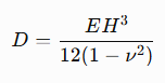
showing that bending rigidity scales with the cube of plate thickness when the other variables remain unchanged. For an isotropic thin plate, bending rigidity can be expressed as:
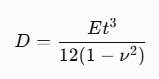
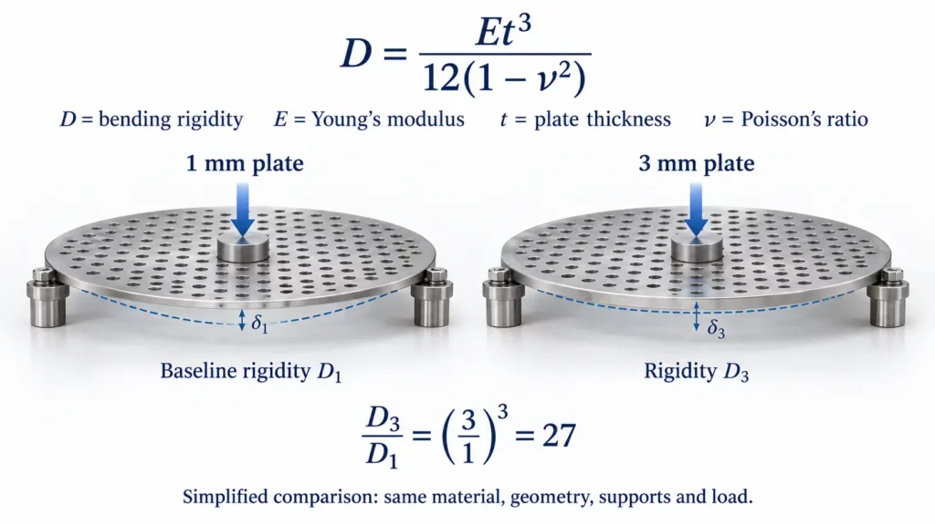
where E is Young’s modulus, tt is plate thickness, and ν is Poisson’s ratio. MIT structural-mechanics material likewise shows plate stiffness scaling with the cube of thickness under comparable geometry and boundary conditions.
Consider a simplified comparison between 1 mm and 3 mm plates of the same material:
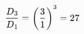
Under those simplified assumptions, the 3 mm plate has about 27 times the bending rigidity of the 1 mm plate.
This does not mean a 3 mm baffle will always perform exactly 27 times better. Hole pattern, open area, plate diameter, supports, boundary conditions, and actual operating loads all change the structural response. The calculation instead demonstrates why a thin plate cannot replace a thick tube-support baffle merely because its hole pattern can be chemically etched.
EPRI also identifies tube vibration as one of the factors affected by baffle design and spacing. Tube support therefore has to remain part of the manufacturing decision rather than being treated as a separate issue after the plate geometry is produced.
Hole Density and Pattern Complexity Change the Economics
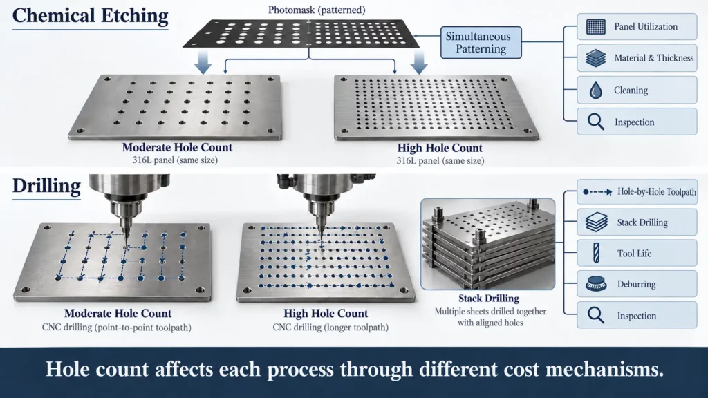
Photochemical machining creates exposed features through the same patterned resist and etching sequence. Increasing a design from 100 to 1,000 holes therefore does not create a tenfold increase in individual cutting-tool cycles.
That does not make hole count irrelevant to etching cost. Panel area, material utilization, thickness, alloy, process conditions, cleaning, inspection, and the number of parts that fit on each production panel still influence manufacturing economics.
Drilling economics are more directly connected with repeated hole-making operations. However, stack drilling can substantially change the calculation.
This is why rules such as “etching becomes cheaper above 100 pieces” should not be used without actual quotation data.
A more defensible comparison is to send the same CAD file, material, thickness, tolerance, and quantity levels—for example 10, 100, and 1,000 pieces—to each feasible manufacturing route. For thin-metal projects under evaluation, a precision chemical etching manufacturer can review the drawing against material thickness, feature geometry, tolerance, panel utilization, and production volume before quotation. The break-even quantity remains project-specific because drilling and etching accumulate cost through different mechanisms.
When Should You Choose Etching, Drilling, or a Hybrid Process?
Chemical etching services becomes a stronger candidate when the part is relatively thin, contains dense repeated apertures or mixed two-dimensional features, requires burr-free edges, and mainly performs a flow-distribution function. Those conditions align with documented PCM strengths in thin, intricate, burr-free metal component manufacturing.
Drilling becomes more attractive as plate thickness, structural support, cylindrical hole geometry, or controlled entrance geometry become more important. It is also an established industrial manufacturing route for conventional heat-exchanger baffle plates, including stacked production.
For some designs, the correct answer is neither “all etched” nor “all drilled.” A hybrid route can use chemical etching for dense flow-distribution features while critical locating, mounting, or tube-contact holes receive secondary machining. For projects that require both etching and downstream operations, a one-stop chemical etching and secondary-processing workflow can reduce supplier handoffs and simplify dimensional responsibility.
How Should Etched and Drilled Baffle Plates Be Inspected?
Inspection should reflect the characteristic risks of each process.
For etched plates, the key checks are front and back opening size, minimum internal opening, hole position, taper or cusp profile, cleanliness, overall dimensions, flatness, and functional gauge passage. These checks respond directly to the undercut and edge-profile behavior of PCM.
For drilled plates, the focus shifts toward hole diameter and position, roundness or cylindricality where specified, burr condition, chamfer or edge break, chips or coolant residue, and deformation after stack machining. Burr formation and interlayer burrs are documented characteristics of drilling and stacked drilling.
What Should Be Included in a Baffle Plate RFQ?
A useful RFQ should include the material grade, thickness, outside dimensions, hole diameter, hole count, pitch, hole pattern, dimensional tolerance, flatness, edge condition, surface requirement, inspection method, quantity, and annual demand. A precision chemical etching manufacturer can use these inputs to evaluate process suitability, DFM risks, inspection requirements, and quotation assumptions.
Three additional questions are especially important:
- Is the plate mainly for flow distribution or structural tube support?
- Will the heat-exchanger tube contact the hole wall?
- Does the specified diameter refer to the surface opening or the minimum usable diameter through the plate?
These questions determine whether stiffness, etched taper, cylindricality, or drilling burrs become controlling requirements.
Process Choice Does Not Replace Compliance
TEMA currently lists the 2026 Edition of the TEMA Standards, which includes new provisions such as an appendix for rod baffles and additional support-design rules. The association states that the revision includes, among other changes, a new appendix for rod baffles and additional rules covering support design.
ISO 16812:2019 specifies requirements and recommendations covering the mechanical design, material selection, fabrication, inspection, testing, and preparation for shipment of shell-and-tube heat exchangers for the petroleum, petrochemical, and natural-gas industries. ISO confirms that the 2019 third edition was reviewed and confirmed in 2024 and remains current.
Neither standard should be reduced to a claim that a component is “compliant” simply because it was etched or drilled. Manufacturing route and equipment compliance are different questions. The finished component still has to meet the applicable drawing, mechanical design, material, support, inspection, and project requirements.
FAQ
Should I choose etching or drilling for my baffle plate?
Start with function, not process. If the plate is mainly a thin flow-distribution sheet with dense or mixed 2D openings, chemical etching is usually the stronger candidate. If it is a thicker structural tube-support baffle that needs near-cylindrical holes and higher stiffness, drilling is typically more natural.
Is plate thickness the first filter between etching and drilling?
Yes. In photochemical machining, minimum hole size scales with material thickness because the etchant removes metal vertically and laterally. A common DFM starting point is hole diameter ≥ ~1.2× thickness for many alloys, with tighter rules as thickness increases. Drilling does not have the same lateral-etch constraint and is more natural for thicker sections.
Are etched holes perfectly cylindrical like drilled holes?
Not necessarily. Etched through-holes can show undercut, taper, or a cusped profile, especially in double-sided etching. Drilled holes are generated by a rotating tool and are easier to treat as near-cylindrical; secondary ops (reaming, boring, chamfering) can further control geometry.
Final Engineering Decision
The most useful decision sequence is:
Function → Thickness → Hole Geometry → Structural Requirement → Inspection → Economics
If the component behaves mainly as a thin, feature-dense flow-distribution plate, chemical etching deserves serious consideration. If it behaves as a thicker structural tube-support baffle with critical cylindrical holes, drilling is usually the more natural starting point. If different regions of the plate have different functional requirements, a hybrid process may be more appropriate than forcing the entire design into one manufacturing method.
For procurement teams, the next step should therefore be to compare manufacturing processes against the same drawing, rather than against generic capability charts. A qualified chemical etching manufacturer should evaluate the same material, thickness, geometry, tolerance, inspection requirements, and quantity used to assess drilling or machining alternatives.
Submit your baffle plate drawing for a manufacturability review. Include the alloy, thickness, outside dimensions, hole diameter, hole count, pitch, tolerance, structural function, inspection requirements, and target quantity. This information allows the geometry to be evaluated for chemical etching, drilling, secondary machining, or a hybrid manufacturing route.