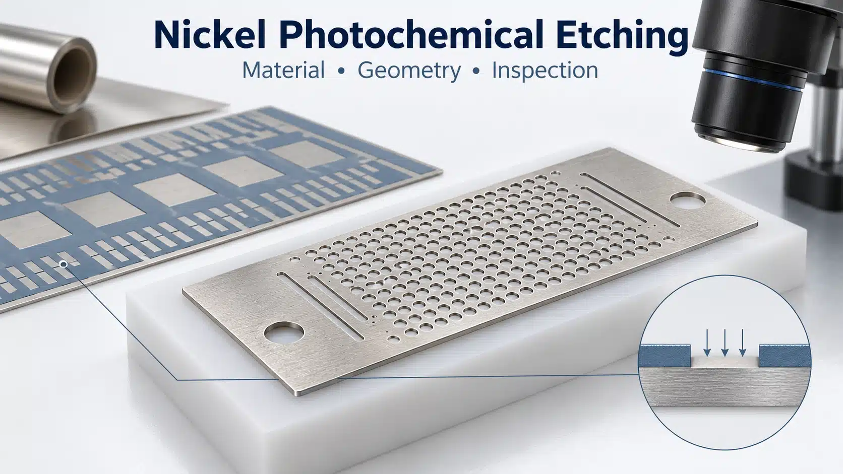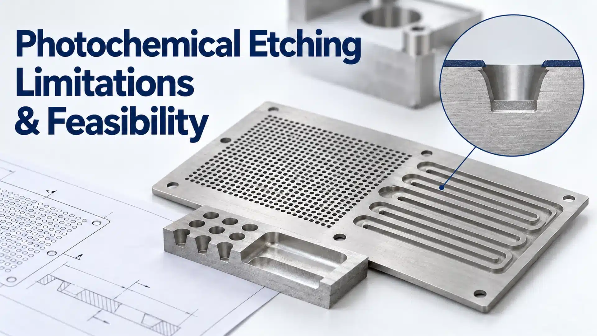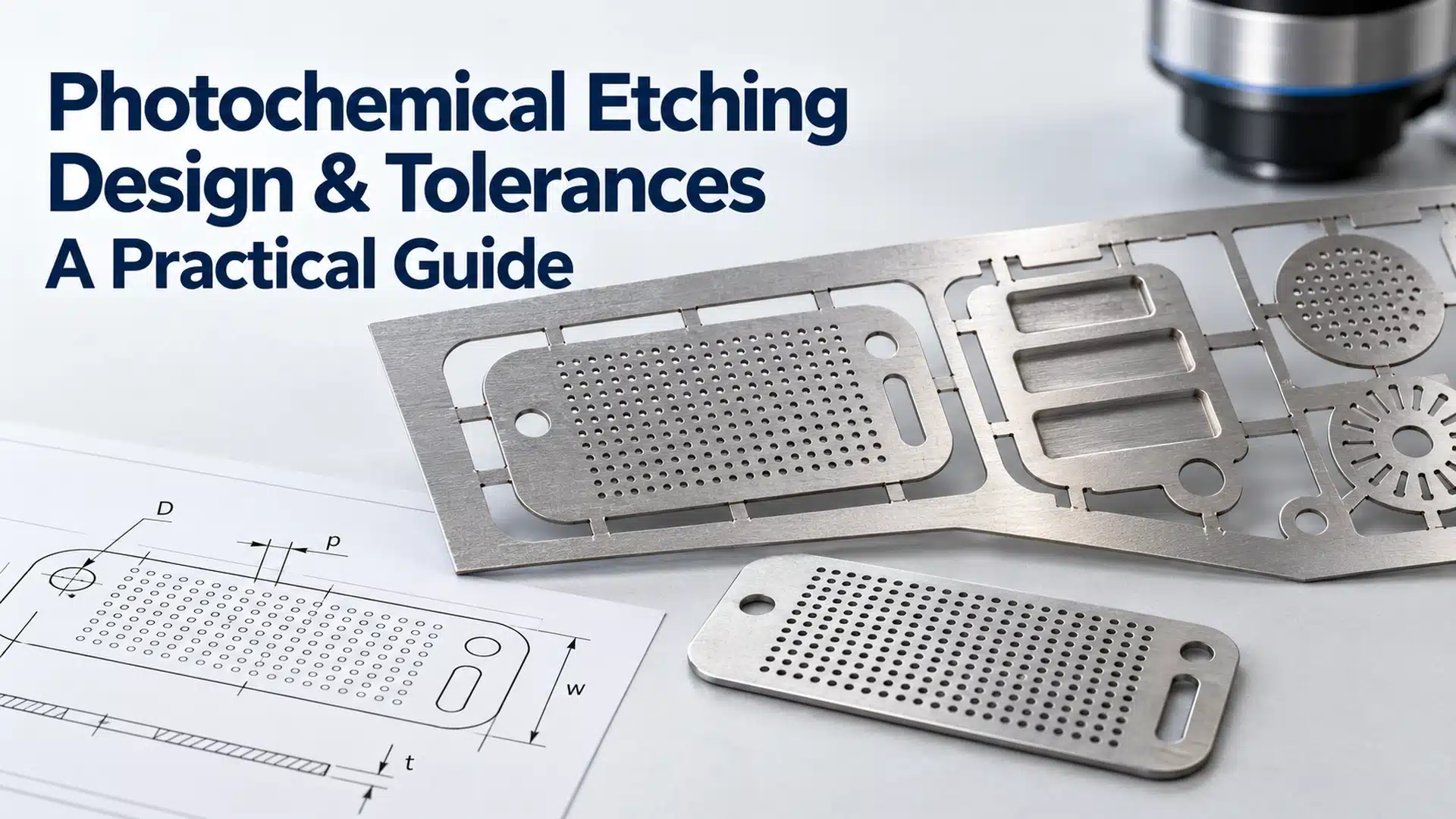

Aerospace photochemical etching uses patterned chemical removal to manufacture thin-metal components, a process also called photochemical machining, or PCM. Representative parts include shielding pieces, shims, contacts and perforated sheets. Review each part’s geometry, material condition, final surface and inspection requirements before approving a manufacturing route.
This guide helps engineers, buyers and supplier-quality teams define the component and the evidence needed for acceptance. For project-specific capability and quotation discussions, use the aerospace photochemical etching services.
Takeaway: Define the part and its delivered condition first, then align the material, drawing, inspection and documentation requirements.
What Aerospace Photochemical Etching Can Produce
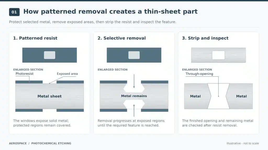
Photochemical etching produces patterns in metal sheet or foil using a light-sensitive protective coating called photoresist. In this guide, photo etching and PCM refer to that manufacturing route.
The process starts with artwork and phototool preparation. The metal is cleaned, coated with resist, exposed and developed to create the protective pattern. Etching removes exposed metal, after which the resist is stripped and the features are inspected.
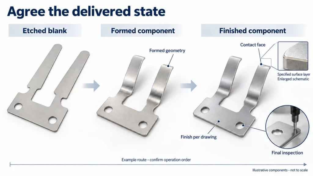
For an aerospace project, define whether the required output is an etched blank, a formed component, a plated part or a component ready for assembly. Include each subsequent operation and its acceptance requirements in the agreed supply scope. This gives the supplier a specific component to assess.
Aerospace Components and What to Verify
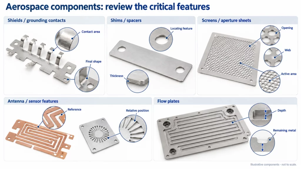
Thin-sheet parts are useful starting points for feasibility review. Established aerospace photo-etched component categories include shims, springs, interconnects, filters and shielding parts.
Use the table below to turn a component name into drawing and acceptance questions. It is a review framework; the applicable requirements come from the particular project.
| Component category | Define the supplied item | What to verify |
|---|---|---|
| Shields and grounding contacts | Flat or formed shielding/contact pieces, with agreed finishing | Contact areas, retaining-tab locations, plating and final shape |
| Shims, spacers and flat springs | Sheet profiles and hole features, with any required forming | Material condition, thickness, flatness, edges and functional requirements |
| Filters, screens and aperture sheets | Perforated sheets with a defined active area | Openings, remaining webs, boundaries, cleanliness and test responsibility |
| Antenna elements and sensor apertures | Specific conductive patterns or sensor/optical openings | Reference features, relative positions, coatings and assembly condition |
| Heat-exchanger and flow plates | Specified plates, channels or fluid-distribution features | Depth, remaining thickness, joining scope and final testing |
For shielding, define electromagnetic interference and radio-frequency interference requirements, commonly shortened to EMI/RFI. Identify who verifies performance in the intended assembly. Similarly, specify any spring-force, electrical-contact or optical requirements alongside the geometry; these need their own acceptance evidence.
For a screen, define the clear opening and the remaining strip of metal between openings, called a web. Agree where these dimensions are measured and whether the active area must remain free of connection points.
Etched Plates and the Complete Assembly
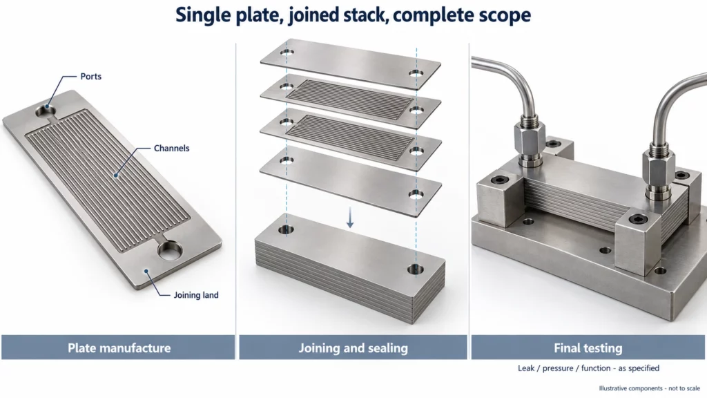
Etched heat-exchanger plates can be combined into bonded stacks. Treat plate manufacture, joining, sealing and final testing as distinct responsibilities when defining the order. Establish who owns dimensional checks before joining and any required leak, pressure or functional tests afterward.
Apply the same scope check to an etched nozzle plate. Confirm whether the request concerns a thin perforated plate, a partial-depth feature or a complete nozzle assembly. Supply the relevant drawing and acceptance requirements for that specific item.
Production Example: Photo-Etched IN718 Spring Contact for an Aerospace Circular Interface
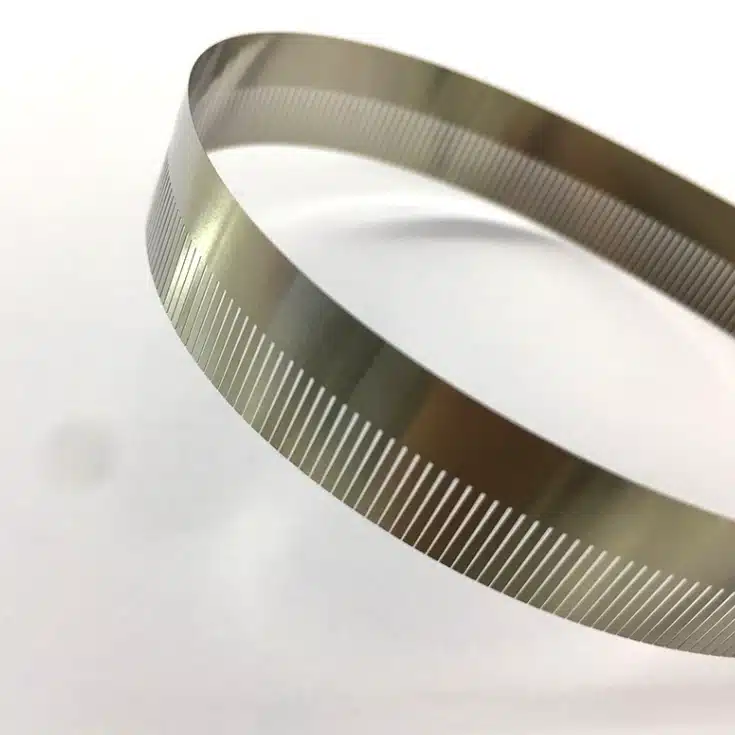
TMNetch produced a precision IN718 spring contact strip for an aerospace circular interface. The part contains hundreds of closely spaced flexible fingers and was photo-etched as a flat strip before being formed into a circular profile.
| Project Data | Specification |
|---|---|
| Material | IN718 nickel-based alloy |
| Thickness | 0.10 mm |
| Formed diameter | Approx. 85 mm |
| Finger width | Approx. 0.28 mm |
| Slot width | Approx. 0.20 mm |
| Critical dimensional tolerance | ±0.03 mm |
| Process | Photochemical etching + circular forming |
| Inspection | Optical dimensional inspection |
The main manufacturing challenge was maintaining consistent finger width, slot spacing, and edge condition across the complete strip while limiting distortion during forming. The continuous metal section also had to remain stable so the individual fingers could flex consistently after the ring was formed.
This type of geometry may be used in aerospace circular interfaces that require compliant contact, grounding, or EMI shielding. The project also shows why the final formed condition, not only the flat etched blank, should be considered during DFM and inspection planning.
Material is based on the actual project. Dimensional values shown here should be replaced with verified production records before publication.
Thin-Sheet PCM and Structural Chemical Milling: Define the Task
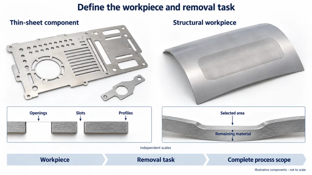
Clarify the workpiece and removal task whenever an inquiry mentions aerospace chemical milling. Photo chemical milling is also used as a PCM term, so the names alone do not establish the manufacturing scope.
Structural applications include selective chemical milling of fuselage skins and contoured parts. Those projects involve a different workpiece and process chain from a small aperture sheet or contact blank.
Ask what material is removed, which geometry must remain, and which preceding and subsequent operations are included. Review the equipment, handling and inspection evidence for the complete workpiece.
An inquiry for an engine blade, wing skin or other large structural item therefore requires its own feasibility assessment. Use evidence specific to that component before accepting the proposed supply scope.
Specify Material Grade, Condition and Final Surface
Grade, Specification and Material Condition
A reviewable material requirement includes the exact grade, applicable specification, supplied condition and thickness requirements. Add the material documentation required by the order. “Aerospace-grade metal” leaves these decisions unresolved.
For stainless steel, identify the particular grade and supplied condition. For aluminum, provide the alloy and temper, meaning its specified material condition. For copper, nickel or nickel-containing alloys, identify the actual designation rather than relying on a family name.
If the drawing specifies titanium or another specialist material, request grade-specific feasibility and stock confirmation. Record any proposed substitution for engineering review before it is used for samples or production.
The photochemical etching material selection guide provides broader material background; the project drawing must still define the selected stock.
Define the Final Surface and Downstream Operations
Specify whether acceptance applies to the etched bare metal, the formed part, the plated surface or another agreed finished state. Mark contact faces, cosmetic areas and surfaces that require protection during processing.
For a formed or coated component, identify the requirements to check after those operations. Agree how the material record, process sequence and final inspection will refer to the same configuration.
Use this compact input chain: grade/specification → condition/thickness → surface/finish → final delivery state.
Drawing Files and Project Requirements for Review
Submit a controlled drawing package that defines the part and the work being purchased. Make the relationship between the two-dimensional drawing and CAD data explicit, including which source controls when information differs.
| Review input | State clearly |
|---|---|
| Controlled drawing | Part number, revision, key notes and document precedence |
| Material and thickness | Grade, specification, condition and thickness requirements |
| Critical features | Assembly/function features, reference locations, connection points and protected areas |
| Delivery scope | Forming, plating, joining, testing and the responsible parties |
| Order and quality requirements | Quantity, batch arrangements, required records and applicable quality clauses |
For a partial-depth feature, identify the etched face and whether depth or remaining metal controls function. For repeated openings, explain which relationships control assembly or performance.
Resolve open quotation assumptions before releasing the order. Record accepted clarifications with the controlled requirements so that the quoted scope, production instructions and acceptance review describe the same part.
Flag conflicting model and drawing dimensions, missing material conditions and undefined finishes for resolution. Keep the accepted reply with the revised package so production and receiving inspection can work from the same decision.
Inspection and Acceptance After Etching and Finishing
Define the Feature and Measurement Condition
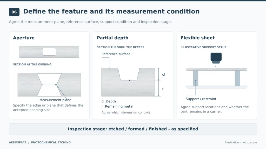
Agree inspection methods around the specified features and measurement requirements. Identify the relevant face, reference features, measurement locations and stage of manufacture.
Include hole geometry, profile, relative position, depth or remaining thickness, and flatness where required by the drawing. For thin flexible parts, agree the support or restraint used during measurement. Confirm which results are required after forming or finishing.
For partial-depth channels, specify a depth-capable measurement method and reference surface. For a critical aperture, agree which edge or measurement plane defines its size. Include those definitions in the inspection instructions.
Check Edges, Cleanliness and Final Finish
Define acceptable edge condition, retaining-tab removal marks and protected surfaces. Specify the required cleaning and packaging arrangements, including how delicate areas should be supported during delivery.
Assess the delivered part against those requirements. A general claim of precision or a clean-looking photograph does not replace the agreed dimensional and surface checks.
Agree on Inspection Reports and First Article Requirements
List the required material records, dimensional reports and certificate of conformity, or CoC, in the order requirements. Confirm what each record covers and which part number, revision or batch it identifies.
First article inspection, or FAI, has a standardized process and documentation framework in the 9102 standard. Where invoked, agree the applicable version, scope and required submission format before production.
Confirm sample approval and any required FAI documentation as distinct deliverables in the quotation. Do not assume that one sample photograph, dimensional report or certificate satisfies every requested record.
Aerospace Supplier Evaluation: Documents and Evidence
Evaluate the supplier against the particular component: material control, drawing revision, relevant capability, inspection evidence and responsibility for subsequent operations.
Verify Traceability and Process Responsibility
Ask how material documents and incoming-stock identification connect to the delivered batch. Check how the approved drawing, CAD data and phototool revision stay aligned.
Identify who performs forming, plating, joining or testing, and how records pass between those operations. Agree how changes, deviations and nonconforming results will be reported and resolved.
Request anonymized examples of the proposed material and inspection records. Check whether they identify the required configuration and results, and confirm that the supplier can provide the same record types for your order.
Check Qualification Claims Against the Actual Scope
AS9100 addresses aerospace quality management system requirements. For a certification claim, verify the named organization, manufacturing site, scope and validity. Review customer approvals and required product-performance evidence separately.
Where International Traffic in Arms Regulations, or ITAR, requirements apply, confirm the supplier eligibility and technical-data arrangements with the project’s responsible team.
Illustrative review scenario: An avionics project needs a formed, plated grounding contact. Submit the material condition, controlled geometry, contact areas and final inspection requirements together. Ask the supplier to identify its forming and plating responsibilities and proposed records. Use that scoped response, representative samples and the required qualification evidence to decide whether to proceed.
When to Compare Photochemical Etching, CNC and Stamping
Compare manufacturing routes when the open question is how to produce the same component. Align geometry, material and condition, quantity, design stability, downstream work and documentation before assessing quotations.
Use the dedicated guide to compare photochemical etching, CNC machining and stamping for aerospace. Keep the finished-part and acceptance requirements consistent across the routes so the comparison covers equivalent deliverables.
Frequently Asked Questions
What thin-metal aerospace components can be photo etched?
Representative categories include shims, contacts, shielding pieces, springs, screens and aperture sheets. Review the exact material, geometry, finishing and delivery scope for the proposed part; the component category alone does not establish manufacturing approval.
How is photochemical etching used in aerospace manufacturing?
It uses a photoresist pattern to protect selected metal while chemical removal creates the required features. The manufacturing route then includes stripping, inspection and any agreed subsequent operations needed for the specified delivered component.
Can photochemical etching produce complete engine blades or wing skins?
These require a component-specific scope review. Structural chemical milling and thin-sheet PCM can describe different manufacturing tasks, so request evidence for the actual workpiece, complete process chain and acceptance requirements before approving supply.
Can an etched nozzle plate be reviewed as an aerospace part?
Yes, as a defined component for feasibility review. Identify whether it is a thin plate, a depth-etched feature or part of a complete nozzle assembly, then provide the drawing, material and required inspection scope.
Is first article inspection required for every aerospace etching order?
Confirm FAI requirements from the customer drawing, purchase order and applicable requirements. Where specified, agree the standard version, coverage and submission format before manufacture. The industry label alone does not define the required package.
Conclusion: Define the Part Before Approving the Process
Start aerospace photochemical etching with a defined component and delivery scope. Confirm the material, controlled drawing and final surface, then agree inspection and documentation before approving production.
To review an aerospace part drawing with TMNetch, submit the drawing revision, material grade and condition, thickness, quantity, final finish and required records. Include subsequent operations and testing responsibilities so the review addresses the complete deliverable.