
A membrane electrode assembly, or MEA, is the electrochemical core of a proton exchange membrane fuel cell. It combines a proton-conducting membrane, catalyst layers, and gas diffusion layers into a structure where hydrogen and oxygen react to produce electricity, water, and heat.
The MEA does not operate alone. It is compressed between PEM fuel cell bipolar plates that distribute reactant gases, collect electrical current, remove heat, and support water management.
For this reason, engineers should evaluate the MEA (with its integrated gas diffusion layers), seals, and bipolar plates as one connected cell structure rather than as separate components.
Quick Takeaways
- A membrane electrode assembly (MEA) is the reactive core of a fuel cell: catalyst layers, a proton exchange membrane (PEM), and gas diffusion layers (GDL) stacked together.
- Two fabrication routes dominate — catalyst-coated membrane (CCM) and gas diffusion electrode (GDE) assembly — trading interface resistance against ease of scaling.
- MEA lifespan and efficiency depend heavily on what surrounds it: bipolar plate flow-field precision directly affects how evenly gas, heat, and water reach the MEA.
- Chemically etched bipolar plates can hold tolerances as tight as ±0.01mm with no mechanical stress on the metal, helping keep MEA operating conditions stable over the stack’s life.
What Is a Membrane Electrode Assembly (MEA)?
A membrane electrode assembly is the part of a PEM fuel cell where the main electrochemical reactions take place. It separates the anode and cathode gases while allowing protons to move through the membrane.
Electrons cannot pass through the membrane. Instead, they travel through an external circuit, where they provide usable electrical power before returning to the cathode.
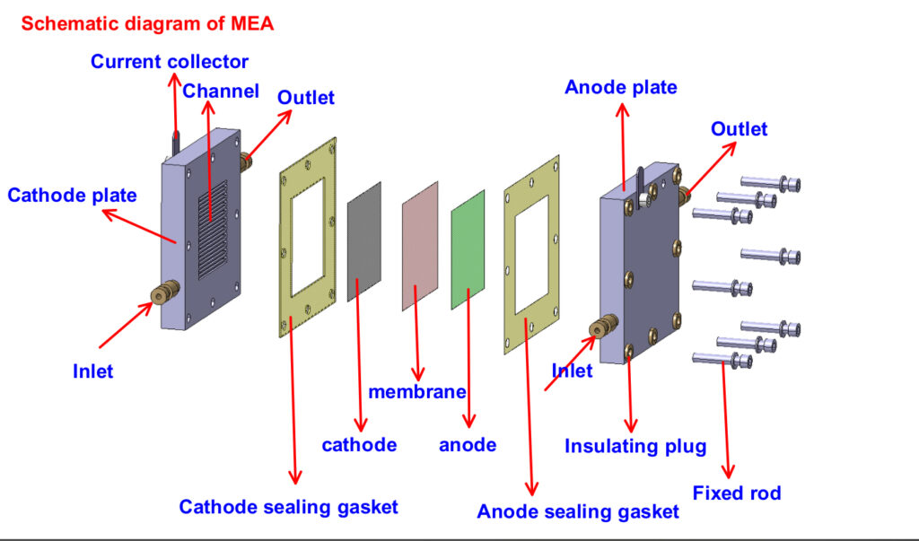
The membrane, catalyst layers, and gas diffusion layers are the main functional parts of an MEA. Bipolar plates are positioned on both sides of the assembly and provide the flow fields needed to distribute hydrogen and oxygen.
In simple terms, an MEA converts the chemical energy of hydrogen and oxygen into electrical energy. Its performance depends on catalyst activity, proton transport, gas diffusion, water management, and contact with the surrounding bipolar plates.
Why Membrane Electrode Assemblies (MEAs) Are the Heart of Fuel Cells
The MEA is the main driver of a fuel cell’s performance, durability, and cost. It’s where hydrogen and oxygen react to produce electricity, with water as the only byproduct — a small structure doing an outsized amount of work.
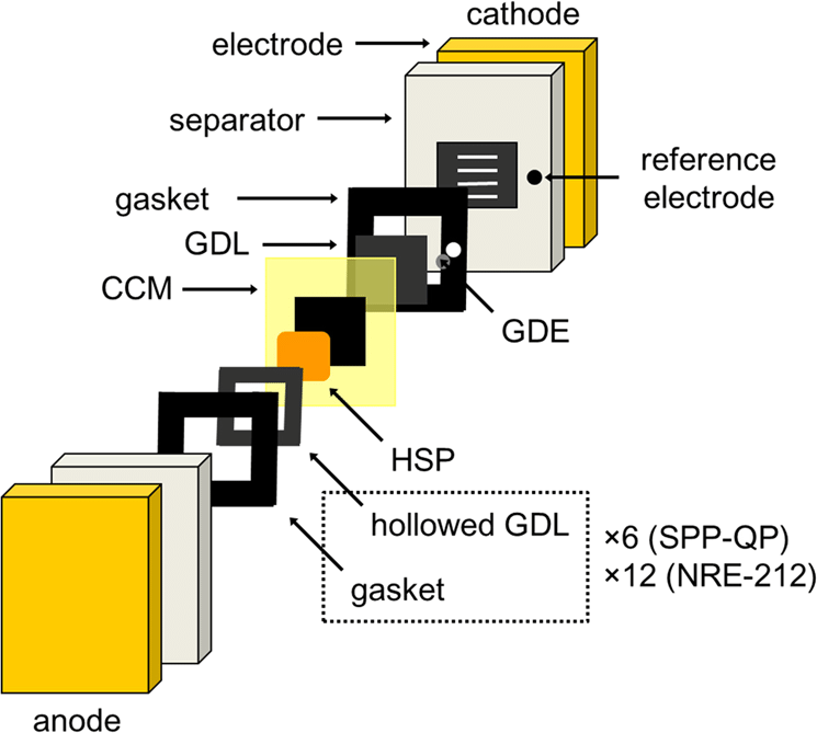
An MEA is built from a few essential parts:
The Catalyst Layer
This is where the core electrochemistry happens, and it plays a different role on each side of the MEA. At the anode, the catalyst splits hydrogen into protons and electrons through the hydrogen oxidation reaction (HOR) — see our breakdown of anode HOR and cathode ORR mechanisms in electrode reactions in fuel cells for more detail. Electrons then travel out through an external circuit to power a device, while protons cross the membrane. At the cathode, oxygen combines with those protons and electrons to form water.
Platinum remains the standard catalyst on both sides, though it’s also the single biggest cost driver in an MEA. That’s pushing ongoing research into transition-metal alloys and other lower-cost, more abundant catalyst options.
The Proton Exchange Membrane
The proton exchange membrane sits at the center of the MEA, doing two jobs at once: conducting protons between electrodes and blocking gases and electrons from crossing over. As a selective barrier, it’s what prevents the cell from short-circuiting internally.
The Gas Diffusion Layer
The GDL’s porous structure spreads gas evenly across the catalyst layer while also managing heat and water movement — get this wrong, and reaction rates become uneven across the active area.
The Role of the membrane electrode assembly (MEA) in Fuel Cells
Beyond the basic chemistry, the MEA plays four functional roles at once:
- A chemical reactor
- An ion conductor
- An electrical separator
- A structural interface
Inside it, protons move directly across the membrane while electrons are forced to take the long way around through the external circuit — that forced detour is what generates usable power.
The membrane also has to keep hydrogen and oxygen from mixing. Any crossover reduces efficiency and shortens the MEA’s life, so it needs to be thin enough for fast proton transport but dense enough to block gas leaks — a genuinely difficult balance to hit.
Water management is the third challenge built into this layer. Too dry and conductivity drops; too wet and gas flow gets choked. A well-designed MEA has to handle both extremes without needing constant correction.
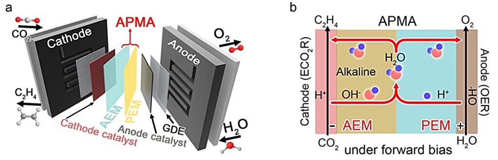
How These Components Work Together
Performance depends on the catalyst layer, membrane, and diffusion layer working in sync. Hydrogen arrives at the anode catalyst and splits into protons and electrons; protons cross the membrane while electrons flow out through the circuit; oxygen and those returning protons and electrons combine at the cathode to form water. When every layer is doing its job, that whole sequence runs efficiently with very little wasted energy.
MEA Fabrication Techniques
Manufacturers generally choose between two common MEA architectures: catalyst-coated membrane (CCM) and gas diffusion electrode (GDE). GDE-based assembly can simplify certain direct-coating workflows, but its performance depends strongly on the interface between the catalyst layer, microporous layer, and membrane.
Catalyst-coated membrane (CCM) applies catalyst layers directly onto the membrane. This cuts interface resistance and tends to deliver better performance, though it demands tighter process control.
Gas diffusion electrode (GDE) assembly applies catalyst layers to the gas diffusion layers first, then presses the whole stack against the membrane. It’s generally easier to scale but can introduce more contact losses at the interfaces.
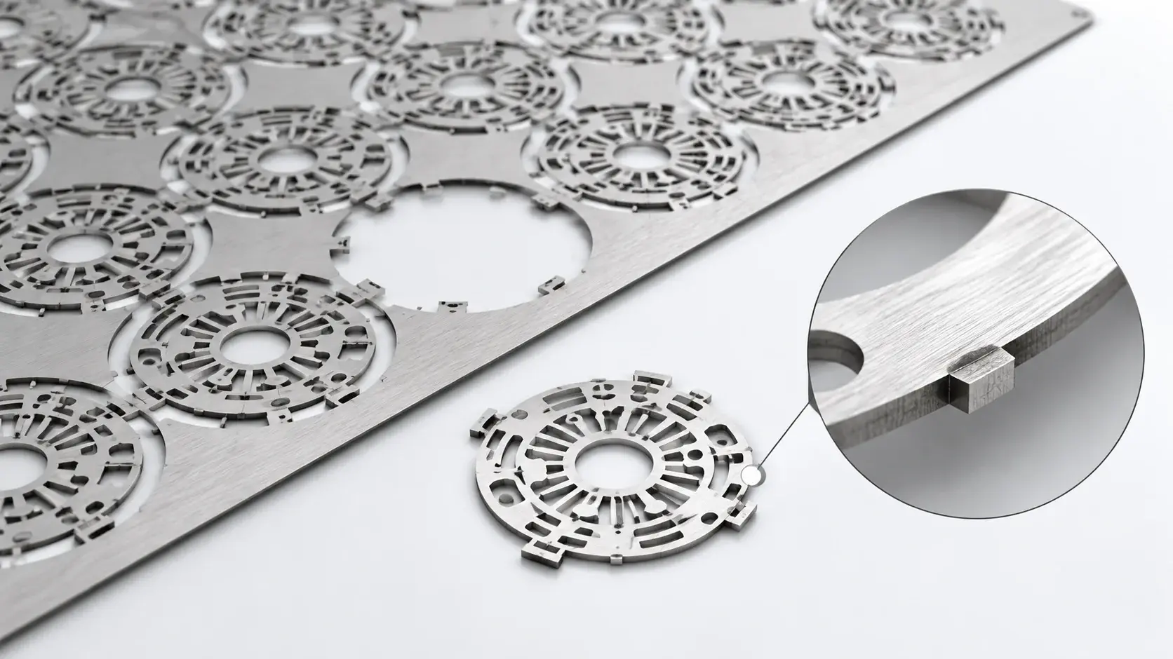
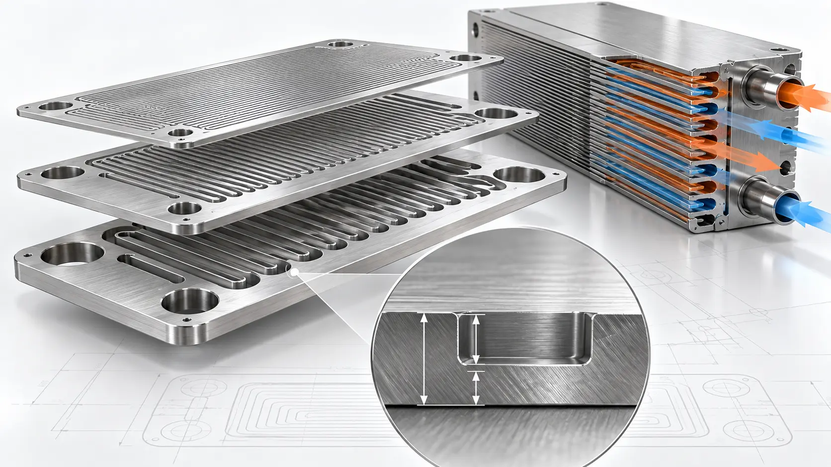
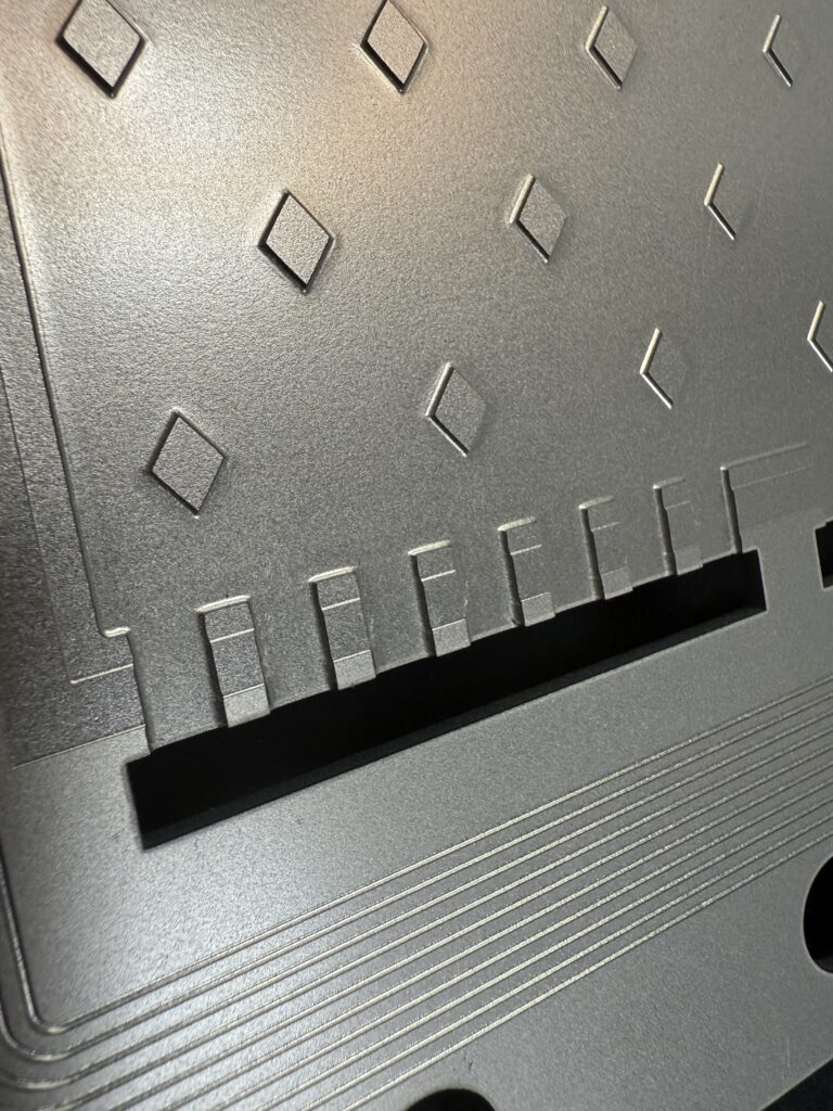
Whichever method is used, precision is non-negotiable — thickness variations measured in microns can change how the finished MEA behaves. That same precision requirement carries over to the bipolar plates positioned against the MEA. On a typical bipolar plate, flow-field channels are chemically etched to depths as tight as ±0.01mm, with no mechanical stress or deformation introduced into the metal, since etching removes material chemically rather than stamping or machining it. Some designs go further with dual-depth channels on a single plate — for example, a 2.0mm-thick plate etched to two different channel depths on one face and a third depth on the reverse — to fine-tune flow and pressure drop across the active area without adding extra parts. Bipolar plate surfaces are typically coated to resist corrosion — for example, with carbon-based films, nitrides, or precious metals like gold or platinum — and the cathode side (oxidizing environment) often demands the more robust protection.
Challenges in MEA Manufacturing
Producing a high-quality MEA at scale isn’t easy, and three challenges dominate the conversation.
Catalyst utilization. Platinum is expensive, and not all of what’s loaded into the MEA actually participates in the reaction. Improving how catalyst particles are distributed remains a major engineering goal — and the biggest lever on overall MEA cost.
Durability. Repeated hydration cycles, temperature swings, and voltage stress slowly degrade the membrane and catalyst layers over time. An MEA needs to survive thousands of operating hours without major performance loss.
Manufacturing consistency. Lab-made MEAs frequently outperform mass-produced ones. Closing that gap — getting production-line MEAs closer to lab-bench performance — is one of the biggest hurdles standing between fuel cells and true mass adoption. Lower-cost, higher-consistency manufacturing across the whole stack, not just the MEA itself, is what will ultimately push fuel cells further into transportation and stationary power.
Advances in MEA Materials
Material science is steadily reshaping what’s possible inside the MEA.
Newer membranes offer higher proton conductivity at lower humidity, and some tolerate higher operating temperatures — which improves reaction kinetics and cuts cooling requirements.
Catalyst research is moving just as fast. Alloy catalysts, core-shell structures, and ultra-low platinum loadings are all aimed at making the MEA cheaper without giving up power output. On the bipolar plate side, manufacturing process selection plays an equally central role in cost reduction. A comparison of bipolar plate manufacturing methods can help engineers evaluate how photochemical etching, stamping, hydroforming, and CNC machining affect tooling cost, channel precision, design flexibility, and production volume.
Ionomer chemistry inside the catalyst layer has also improved, and better ion transport means more of the catalyst’s active sites actually participate in the reaction — which translates directly into higher efficiency.
Impact of MEAs on Fuel Cell Efficiency and Life
The MEA shapes both how efficiently hydrogen converts to electricity and how long the whole fuel cell system lasts.
A well-designed MEA keeps internal resistance low, which means less wasted energy, less heat, and slower material degradation over time.
Poor MEA design works the other way — membrane thinning, catalyst dissolution, and carbon corrosion typically start inside the MEA, and once those processes begin, they’re rarely reversible. That’s why fuel cell warranties so often trace back to MEA performance data: the MEA effectively sets the ceiling on how long the system can realistically run.
Applications of MEAs in Different Fuel Cell Types
MEA design isn’t one-size-fits-all — different fuel cell types call for different approaches.
In proton exchange membrane fuel cells (PEMFC), the MEA is optimized for fast proton transport and low-temperature operation, which is why they dominate vehicles and portable power.
In direct methanol fuel cells (DMFC), the MEA has to resist fuel crossover, which calls for different membrane chemistry and catalyst structures.
Solid oxide fuel cells don’t use an MEA in the traditional sense, but hybrid concepts still borrow ideas from MEA design, particularly at material interfaces.
The core concept carries across all of these — even as the specific materials change.
MEA Cost Considerations and Scalability
Cost remains the biggest barrier to mass fuel cell adoption, and platinum loading in the MEA is the largest single line item behind it. Bringing that cost down without sacrificing performance is what will ultimately decide how fast fuel cells scale into transportation, stationary power, and beyond.
That same cost pressure runs through the rest of the stack, not just the MEA. For custom metal bipolar plates, manufacturing cost depends on material, plate thickness, flow-field geometry, channel depth, coating, tooling requirements, prototype quantity, and production volume. Chemical etching can be attractive when designs change frequently because it avoids hard tooling used in conventional stamping.
Future Trends and Innovations in MEA Technology
The future of the Membrane electrode assembly looks promising. Researchers are exploring non-platinum catalysts that could redefine cost structures. Others are developing reinforced membranes that resist mechanical stress longer. Digital tools also play a role. Simulation-driven design helps optimize Membrane electrode assembly structure before physical testing. That saves time and materials.
In the long run, we may see modular MEA designs tailored to specific use cases. Instead of one generic Membrane electrode assembly, systems could swap optimized versions based on load, climate, or duty cycle.
While the Membrane electrode assembly sits at the center of fuel cell performance, it never works alone. Its real-world behavior is deeply influenced by the components that surround it, especially the bipolar plate.
Bipolar plates manage gas distribution, current collection, and heat removal across the stack. Their surface quality and bipolar plate flow-channel design directly affect how evenly reactants reach the membrane electrode assembly. Poor flow uniformity can lead to localized drying or flooding inside the MEA, shortening its life even if the MEA itself is well designed.
This is where advanced manufacturing methods like TMNetch chemical etching start to matter. Compared with traditional machining, chemical etching enables finer flow-field patterns, smoother channel walls, and tighter tolerances on bipolar plates. These improvements help stabilize operating conditions at the MEA interface, supporting more consistent electrochemical reactions over time.
As fuel cell systems continue to mature, engineers are increasingly treating the Membrane electrode assembly, bipolar plate design, and manufacturing processes as a single integrated system rather than isolated parts. Optimizing MEA performance now means looking beyond the membrane itself and considering how innovations in areas like chemical etching can quietly but meaningfully raise the ceiling for efficiency, durability, and scalability.
In the end, progress in fuel cell technology is rarely about one breakthrough component. It’s about how well every layer works together, from the Membrane electrode assembly at the core to the etched channels guiding gases around it.
MEA and Bipolar Plate: Why the Interface Matters
The MEA sits at the center of fuel cell performance, but it never works alone. Its real-world behavior is shaped heavily by the fuel cell bipolar plate surrounding it.
Bipolar plates handle gas distribution, current collection, and heat removal across the stack. Their surface quality and channel precision directly affect how evenly reactants reach the MEA. Uneven flow can cause localized drying or flooding inside the MEA, shortening its life even when the MEA itself is well designed.
This is where manufacturing method matters more than it might seem. Chemically etched bipolar plates avoid the mechanical stress that stamping or machining can introduce into thin metal sheets, which keeps flow-field channels consistent across the full plate area. In production, this level of control supports finer flow-field patterns, dual-depth channel designs on a single plate, and tolerances as tight as ±0.01mm — the kind of consistency that keeps operating conditions stable at the MEA interface over the stack’s working life. While chemical etching can handle a wide range of metals — including stainless steel, titanium, aluminum, and copper — the harsh environment inside a PEM fuel cell means that practical bipolar plate material choices are overwhelmingly limited to stainless steel (304L, 316L, etc.) and titanium grades that balance corrosion resistance and conductivity.
As fuel cell systems mature, engineers increasingly treat the MEA, bipolar plate design, and manufacturing process as one integrated system rather than isolated parts. Getting more out of the MEA now often means looking beyond the membrane itself, toward how the components around it are made.
FAQ
What are the three main layers of a membrane electrode assembly?
At its core, an MEA is built from a proton exchange membrane (PEM) sandwiched between two catalyst layers (anode and cathode), with a gas diffusion layer (GDL) on each outer face.
How long does an MEA typically last in a fuel cell stack?
Lifespan varies by application and operating conditions, but MEAs are generally engineered to run for thousands of hours before performance degrades meaningfully — automotive and stationary power applications set different durability targets.
What causes MEA degradation over time?
The main drivers are membrane thinning, catalyst dissolution, and carbon support corrosion — all accelerated by repeated hydration cycling, temperature swings, and voltage stress.
CCM vs. GDE — which fabrication method is better?
Neither is universally better. CCM (catalyst-coated membrane) typically delivers lower interface resistance and stronger performance, while GDE (gas diffusion electrode) assembly is generally easier to scale, at some cost to interface quality.
How does bipolar plate design affect MEA performance?
Bipolar plate flow-field precision determines how evenly gas, heat, and water reach the MEA. Poor flow uniformity can cause localized drying or flooding inside the MEA, shortening its life even when the MEA itself is well designed.
Do all fuel cell types use the same MEA design?
No. PEMFCs optimize the MEA for fast proton transport at low temperatures, DMFCs need MEAs that resist fuel crossover, and solid oxide fuel cells don’t use a traditional MEA structure at all.
Conclusion
The MEA may be small and hidden inside a fuel cell stack, but its importance is hard to overstate. It’s where fuel becomes usable power, and its design sets the ceiling for a fuel cell’s performance, maintenance needs, and cost.
As fuel cells move from niche technology toward mainstream energy use, the MEA will stay at the center of that progress — but so will everything built around it. If fuel cells are the engine of a clean energy future, the MEA is the piston that makes it move, and the bipolar plates around it are what keep that piston running smoothly, stack after stack.
For fuel cell stack manufacturers developing custom flow fields, TMNetch’s custom bipolar plate manufacturing capabilities support precision etching, material selection, channel geometry, coating, prototyping, and production requirements. For projects that also require plating or secondary finishing, one-stop processing can be evaluated after the bipolar plate design and manufacturing route have been confirmed.