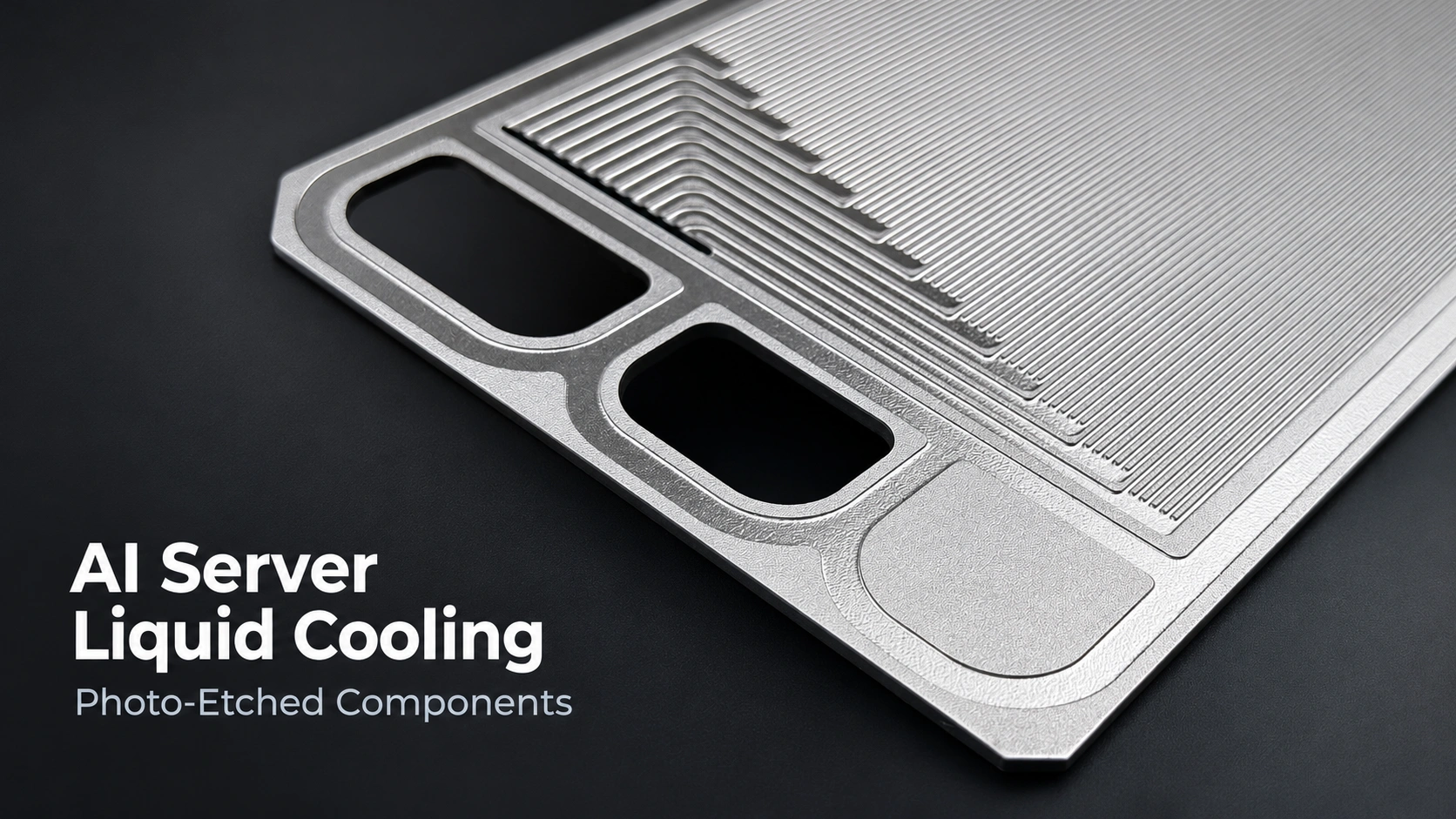

To avoid scratches in bipolar plates, control contact with tools, particles and adjacent sheets throughout manufacturing. Inspect surfaces at process handovers, then evaluate any mark against its location, measured geometry and drawing requirements. Mechanical surface damage can occur during handling, shipping and assembly, so protection must extend beyond the etching operation.
This guide focuses on photo-etched metallic bipolar plates. Photochemical etching uses photoresist to define where metal is removed. Preventing mechanical damage and controlling the etched pattern are connected tasks, but they require different checks.
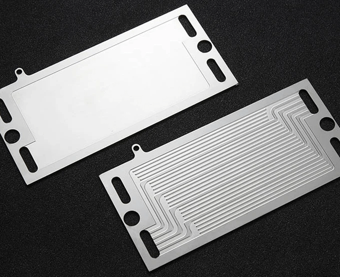
Is It a Scratch or an Etching Defect?
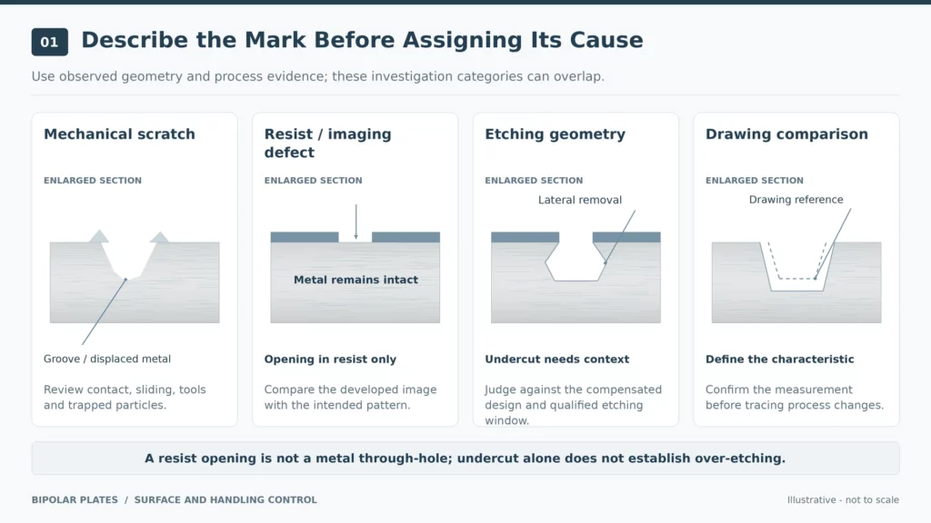
Start by describing what is visible before naming its cause. Record the affected surface, position and direction. Then compare the mark with the drawing and available process records.
The following troubleshooting matrix separates the questions an investigation should answer.
| Investigation category | What to examine | First investigation step |
|---|---|---|
| Mechanical scratch | A groove, displaced material or a directional mark | Review sliding contact, tools, fixtures and trapped particles |
| Photoresist or imaging defect | Unwanted openings, damaged resist or an incorrect developed pattern | Compare the developed image with the intended pattern |
| Excessive etching | Too much removal or lateral loss relative to the compensated design | Review the etching window and pattern compensation |
| Dimensional deviation | Channel width, depth, rib width or position outside specification | Confirm the measurement, then trace relevant process changes |
These categories can overlap. A damaged resist layer may permit unwanted etching, producing a dimensional deviation. Conversely, a channel outside tolerance may have no mechanical scratch.
Photoresist defects and contamination need investigation at the image-transfer stage. An opening in the resist does not, by itself, establish a hole through the metal.
Likewise, lateral etching beneath the resist is an expected consideration in isotropic wet etching. Judge the finished geometry against the compensated design instead of labelling every undercut as over-etching.
This distinction determines the corrective action. Handling changes address unwanted contact; pattern and etching reviews address unintended material removal.
How Can Scratches Be Prevented at Each Manufacturing Stage?
Use a control plan organized around three questions: what touches the plate, what could move against it, and what evidence confirms its condition before transfer?
The following measures are recommended planning steps. Select and validate them for the material, geometry and cleanliness requirements.
Incoming Sheet, Cutting and Initial Handling
Inspect and record the incoming sheet’s exposed surfaces before processing. Preserve the material lot identity and note existing marks so they can be distinguished from later damage.
Where the drawing specifies Titanium Grade 2, verify the material certificate and supply specification. ASTM B265 covers titanium strip, sheet and plate; material identification remains a separate check from surface acceptance.
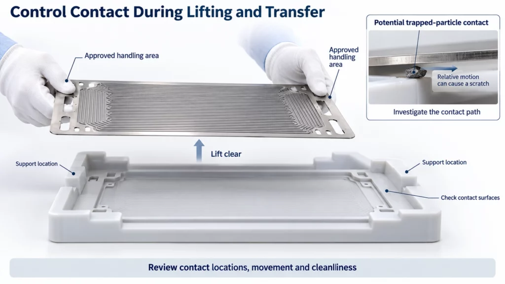
When cutting bipolar plates or preparing blanks, review cut edges, supports and transfer trays together. Plan a lifting method that avoids dragging functional surfaces across fixtures or other sheets. Support the blank during transfer and identify approved handling areas.
Check the contact surfaces before loading the next batch. Do not assume that a tray remains suitable because the previous batch passed inspection. Record the blank’s condition before it enters the next operation.
Loading, Resist Processing and In-Process Transfer
Distinguish scratches in the metal from damage to the photoresist. Inspect the developed pattern for continuity and unwanted openings before exposing the workpiece to etchant.
Particles and substrate cleanliness can affect resist-film uniformity. Review cleaning, contact surfaces and resist preparation when abnormalities appear, rather than treating every visible line as a handling scratch.
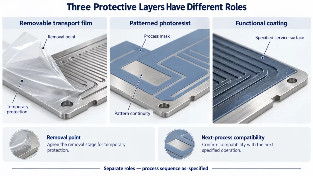
Keep three protective layers conceptually separate: removable transport film, process photoresist and the finished functional coating. Specify when temporary protection is removed and confirm compatibility with the following operation.
TMNetch’s published titanium-plate workflow includes protective plastic films on both sides and checks for surface blemishes. For a new order, agree the exposed-surface inspection point and film-removal sequence explicitly.
At each handover, identify who releases the material and what happens if the resist or substrate shows damage. Avoid continuing an uncertain part through several operations before reviewing it.
Etching, Stripping, Rinsing and Drying
Control mechanical contact during loading, unloading and movement between process stages. Review rack contact points and transfer arrangements against the approved handling areas.
Separately, maintain the validated etching window. Etching time, temperature and concentration can affect material removal, roughness and undercut in stainless-steel photochemical machining. Establish settings for the actual alloy and pattern through process qualification.
Changing etching parameters is not a repair method for a mechanical scratch. If the metal is damaged, isolate the part and assess its remaining geometry before considering further processing.
After stripping, rinsing and drying, inspect the exposed metal under defined conditions. Record the first stage at which an anomaly becomes visible. Preserve photographs and the relevant process history before additional cleaning or rework.
Final Inspection, Packing and Transport
Include inspection equipment in the contact review. Check fixture cleanliness, support locations and loading methods before placing an accepted plate on the measuring setup.
For packing, select suitable separators, supports or individual locations to limit plate-to-plate contact and relative movement. Confirm that packaging materials meet the project’s cleanliness and surface requirements.
Check the packed condition as well as the loose part. A plate that fits a tray during loading still needs an agreed method of restraint for transport.
Use shipment and receiving photographs with identifiable orientation and batch information. These records support comparison when a customer reports a new mark. Ask the receiving team to document the packaging before removing or rearranging the parts.
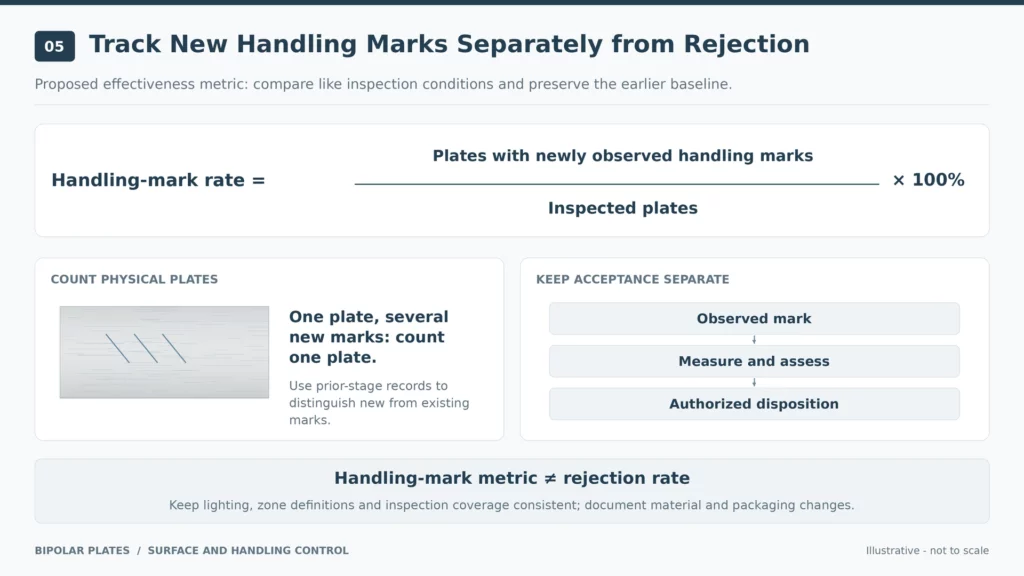
Proposed effectiveness check: Before trialling a handling change, define the metric. One option is the number of plates with newly observed handling marks divided by the number inspected. Compare batches under the same lighting, zone definitions and inspection coverage. Keep this measure separate from the rejection rate: a recorded mark may meet the agreed acceptance criteria. Document changes in material, geometry or packaging alongside the results.
How Should Bipolar Plate Scratches and Flow Channels Be Inspected?
Separate finding an anomaly from measuring it. Visual screening locates a suspect area; dimensional inspection determines whether the relevant characteristic meets its limit.
Locate and Record the Surface Defect
Agree the lighting, viewing angle, magnification and reference samples used for visual inspection. Record which face was inspected and locate the mark using drawing coordinates or an agreed zone map.
Include an overview image and a close-up with a scale. Preserve the original image rather than relying only on an annotated crop.
Compare records from consecutive operations. The station that first detects a defect is the starting point for investigation, not automatic proof of where it originated.
For repeat problems, compare mark direction and location with the contact points used at each stage. Treat a match as a lead to verify through observation or a controlled check.
Measure Defect Geometry and Channel Dimensions Separately
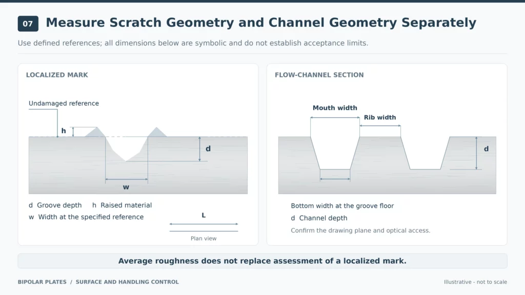
Where acceptance depends on depth, use a validated measurement method suitable for the surface and feature. Three-dimensional scratch measurement can quantify a groove along its length. A conventional two-dimensional photograph does not provide that height information.
For channel inspection, define the measured section. Channel-mouth width, bottom width and rib width are different characteristics. Keep their references consistent between the drawing and report.
Non-contact bipolar-plate inspection can address fine flow-field geometry, but sensor access and surface response still require evaluation. Steep slopes can cause missing data in optical surface measurements. Review the measured region before accepting a complete-looking colour map.
| Inspection task | Useful output |
|---|---|
| Surface screening | Location, images, provisional category and first detection stage |
| Local geometry | Required depth, width, length and displaced-material measurements |
| Flow-channel inspection | Defined channel, rib and profile results |
| Traceability | Drawing revision, lot, method and disposition status |
Do not substitute an average roughness result for assessment of a localized mark. Record the anomaly and surrounding geometry separately.
What Makes a Scratch Acceptable or Rejectable?
Define acceptance before manufacturing. Use the drawing or inspection agreement to specify which surfaces matter and which defect characteristics control release.
Surface-imperfection terminology provides a shared language for describing marks. It does not establish an allowable scratch depth for every bipolar plate. The table below is a proposed agreement framework.
| Requirement to agree | Question to resolve |
|---|---|
| Evaluation zone | Is the mark in a channel, rib, sealing area, joining area or non-functional border? |
| Defect parameters | Which limits apply to depth, width, length, raised material, quantity or penetration? |
| Inspection conditions | What lighting, magnification, method and coverage are required? |
| Decision rule | How will uncertainty be handled near a dimensional limit? |
| Disposition authority | Who approves remeasurement, rework, concession or rejection? |
| Subsequent verification | What additional coating, sealing or functional checks are required? |
For numerical limits, agree conformity decision rules that consider measurement uncertainty. A result close to the limit needs evaluation under that rule.
When results are inconclusive, retain the original evidence and agree whether additional measurement is needed. Identify affected stock and document any customer-approved concession, including its lot and feature scope, before release.
Assess each zone against its stated function and requirements. Avoid automatically rejecting every visible mark or accepting every mark inside a flow channel. Keep material identity, dimensional conformity and surface acceptance as separate recorded decisions.
For example, consider two hypothetical marks with the same measured depth: one crosses a specified sealing contact area; the other lies on an approved handling border. Their acceptance requirements may differ. Without the location and applicable drawing note, depth alone cannot resolve the decision.
If a mark affects a surface intended for coating, transfer the findings into the review of how etching quality affects coating performance. Manufacturing inspection should provide the location and measured condition needed for that assessment.
TMNetch Case: Clarifying a Customer’s Defect Concern
In a previous TMNetch etching order, a customer questioned small connection points around the parts. The factory explained that these were intentional retaining tabs and could be reduced where the design and processing conditions allowed.
The customer accepted them provided they did not affect the finished part’s functional area. This documented retaining-tab case concerned general etched parts, rather than a bipolar-plate scratch trial.
Its practical lesson applies to defect discussions: identify the feature, establish its location and relate acceptance to function. For bipolar plates, turn that discussion into measurable requirements for the affected area. The recommended follow-up is an approved drawing note or inspection agreement, rather than a general statement that visible marks are acceptable.
FAQs About Bipolar Plate Scratch Prevention
Does chemical etching eliminate the risk of scratches?
No. Review contact during incoming inspection, loading, cleaning, measurement, packing and transport. Etching controls alone do not cover the entire manufacturing chain.
Are all flow-channel marks caused by mechanical scratches?
No. Compare the mark with the developed resist pattern, etching records and dimensional results before assigning a cause. Appearance alone is insufficient.
Can a scratched bipolar plate be polished or re-etched?
Only after engineering review. Isolate it first, define an approved rework route and recheck the resulting geometry and surface condition. Include any required downstream verification.
Review Surface and Inspection Requirements Before Etching
Planning custom etched bipolar plates? Share the drawing, material grade, channel dimensions, critical surface zones and inspection requirements with TMNetch.
Include the expected delivery condition, proposed acceptance rules and responsibility for any later coating or assembly. These inputs provide a basis for reviewing handling, manufacturing and inspection before sampling.
Discuss your requirements through TMNetch’s chemical etching services so that the quotation and sample review address the same finished-part condition.