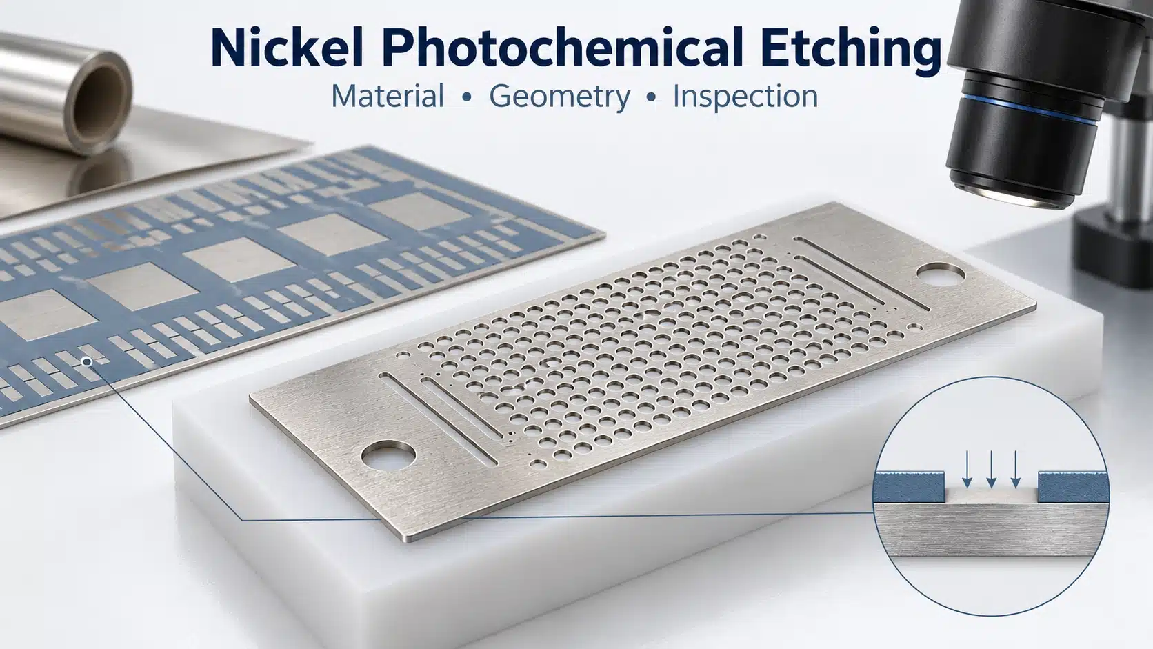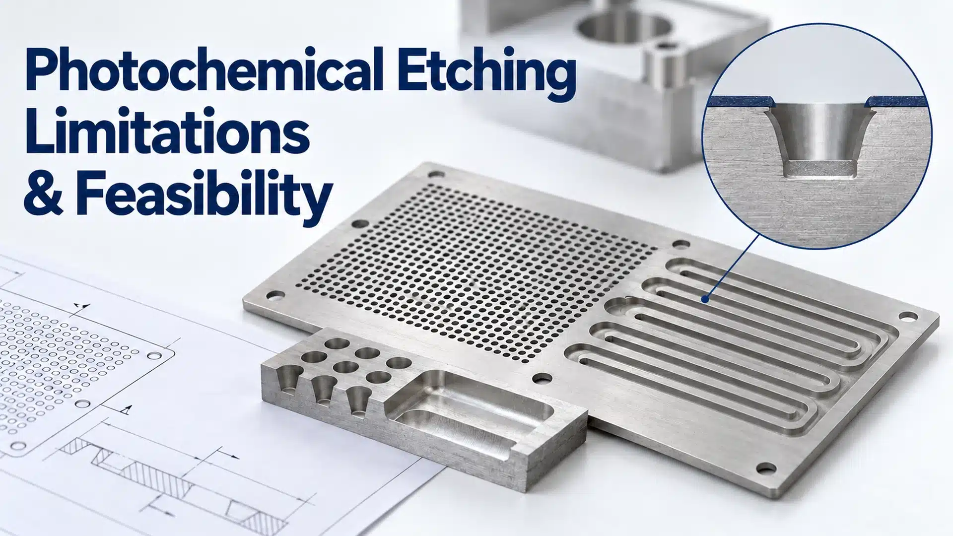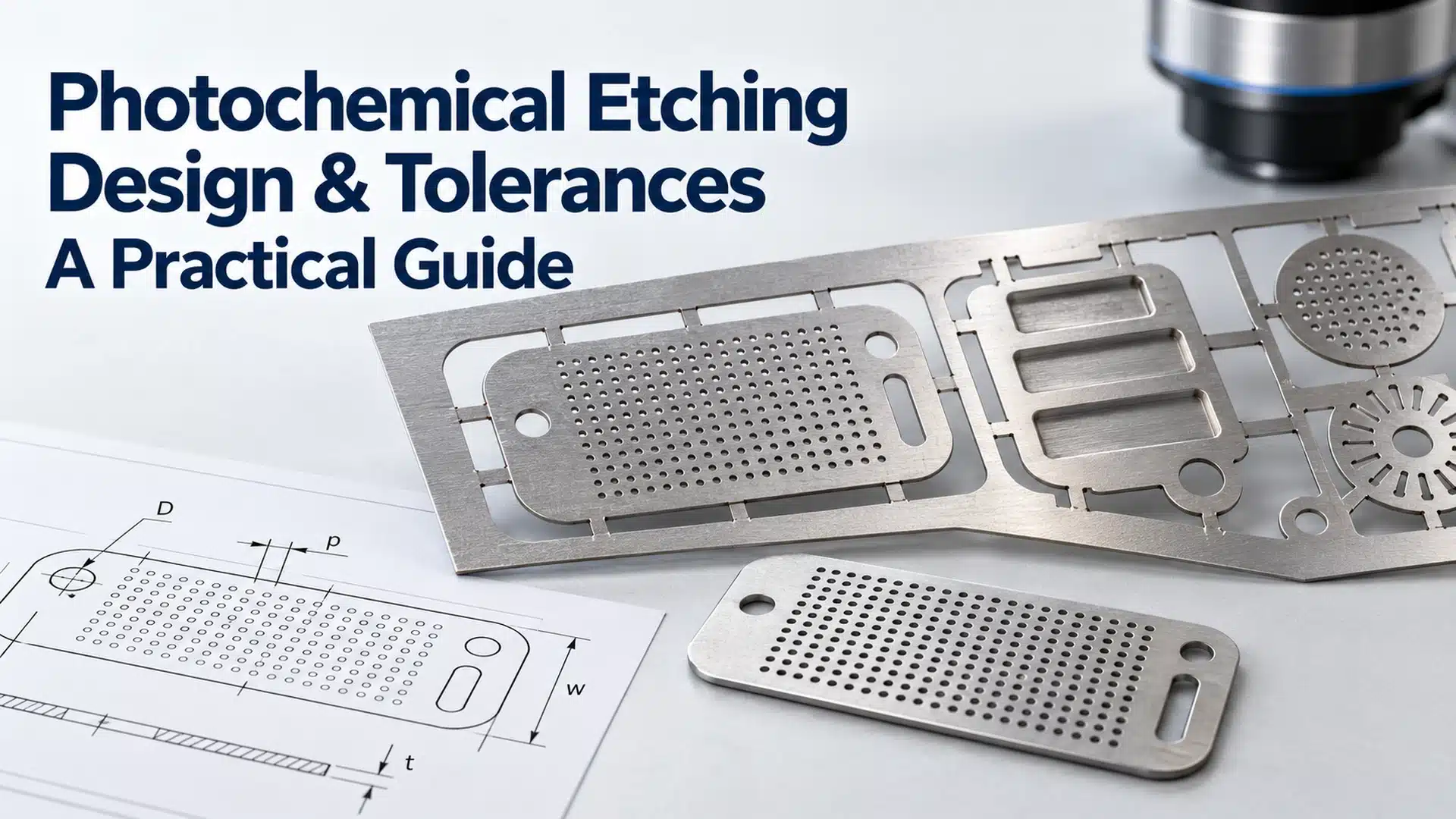

Photo etching uses photoresist, ultraviolet light, and controlled chemical removal to produce detailed parts from thin metal sheet. It is also called photochemical etching, photo chemical etching, or photochemical machining. These terms usually describe the same industrial process.
Knowing the steps alone does not guarantee a good part. Surface cleanliness, phototool accuracy, resist adhesion, exposure, etchant condition, spray distribution, and inspection all affect the result. This guide explains those controls and common photo etching defects.
Key Takeaways
Photo etching quality begins with the drawing, material specification, and inspection plan.
Cleaning, photoresist, exposure, and development must be controlled before the metal reaches the etching machine.
Etchant condition, temperature, exposure time, and spray distribution affect feature size and uniformity.
Undercut is an expected part of wet etching and must be considered during phototool design.
Defects should be traced to the process stage that created them, not corrected by simply etching the part again.
What Is Photo Etching?
Photo etching is a subtractive manufacturing process for thin, flat metal components. A photoresist protects the areas that must remain. UV exposure and development create openings in the resist, and a compatible etchant removes the exposed metal. The remaining resist is then stripped away.
The process transfers an entire pattern at the same time. Holes, slots, outside profiles, and selected half-etched features can therefore be included in one design. Metal is removed without a cutting tool or direct cutting heat.
This page uses photo etching as the main term. Photochemical etching and photo chemical etching are used as natural variants rather than separate processes.
What Must Be Reviewed Before Production?
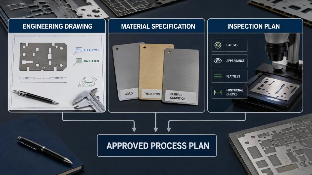
Process control starts before the first sheet is coated. The drawing, material, geometry, and inspection requirements should be reviewed together.
Drawing and Phototool Review
The drawing should identify critical dimensions, datums, full-etched openings, half-etched features, and any areas that require special inspection. Engineers then prepare the phototool and add process compensation where required.
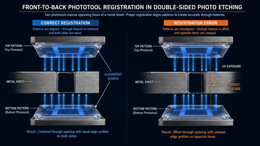
Front-to-back registration is especially important for parts etched from both sides. Poor alignment can shift holes, change edge profiles, or create unequal features on opposite faces.
Material and Surface Condition
Material grade and thickness affect etch response, feature limits, and the amount of lateral removal. Surface contamination, oxidation, scratches, or inconsistent flatness can also affect photoresist adhesion and etching uniformity.
For a broader review of compatible alloys, see this guide to photochemical etching materials.
Inspection Requirements
The supplier must know which dimensions are critical and how finished parts will be accepted. The inspection plan may cover dimensions, appearance, flatness, surface condition, and function. The method should match the feature size.
How to Photo Etch Metal: Step-by-Step Process
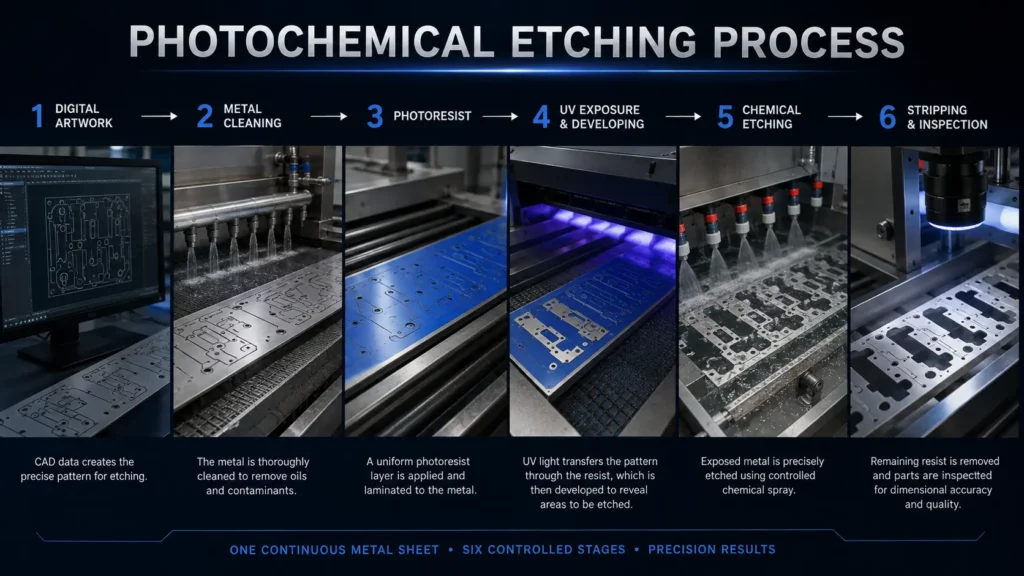
The industrial photo etching process can be summarized in six stages:
Drawing and phototool preparation: Engineers review the CAD file and prepare the compensated image used to transfer the pattern.
Metal preparation: The specified sheet is inspected, cleaned, and prepared so the photoresist can bond evenly.
Photoresist, exposure, and development: Resist is applied to the metal. The phototool is aligned, UV light transfers the pattern, and development exposes the areas to be removed.
Chemical etching: A compatible etchant removes the unprotected metal. Industrial equipment controls the reaction and may spray both sides of the sheet.
Stripping and cleaning: The remaining resist and process residues are removed before the parts are dried.
Inspection and secondary operations: Dimensions and appearance are checked. Forming, plating, heat treatment, or other operations are added only when the drawing requires them.
For a detailed explanation of every production stage, read the complete photochemical etching process and design guide.
Which Variables Control Photo Etching Quality?
Surface Cleanliness
Oil, fingerprints, dust, oxides, and previous processing residues can prevent the resist from bonding to the sheet. Poor preparation may cause resist lifting, pinholes, incomplete protection, or uneven etching. Cleaning must produce a consistent surface without damaging the starting material.
Photoresist Application
The resist must cover the working area without bubbles, folds, dust, or weak edges. Its condition should be checked before imaging. A small defect in the resist can become an unwanted opening or pit after chemical etching.
Exposure, Alignment, and Development
Exposure must form a stable image in the resist. Development must then open the intended areas without damaging protected features. Underdevelopment can leave residue over metal that should be removed. Excessive development may weaken fine resist features.
Alignment also affects dimensional accuracy. On a double-sided sheet, registration errors can produce offset edges or unequal openings even when the chemical reaction is stable.
Etchant Condition and Compatibility
The correct etchant depends on the metal or alloy. Ferric chloride (FeCl₃) is widely used in industrial photochemical machining, but its composition changes as metal dissolves into the solution, so etchant condition must be monitored to maintain a consistent etch rate and dimensional control.
Temperature and Etching Time
Temperature changes the reaction rate. Etching time or conveyor speed determines how long the exposed metal remains in contact with the solution. Too little exposure can leave incomplete openings. Too much can enlarge features and increase lateral etching beneath the resist.
Spray Flow and Distribution
In spray etching, nozzle condition, pressure, flow, and sheet position affect solution delivery. Uneven distribution can create different results across one panel. Top-to-bottom imbalance can change a double-sided profile.
Undercut and Dimensional Compensation
Wet etching removes metal downward and sideways. The sideways action beneath the photoresist is called undercut or lateral etching. It is a normal process characteristic rather than proof that a part is defective.
Undercut depends on material, thickness, geometry, etchant condition, and process time. Thicker material generally requires a longer removal path, so narrow holes, slots, and webs need careful review.
Engineers compensate for the expected material removal when preparing the phototool. The required adjustment is project-specific. Designers should therefore avoid applying one universal minimum feature rule to every metal and thickness.
Common Photo Etching Defects and Troubleshooting
| Defect | Likely causes | Prevention or review point |
|---|---|---|
| Incomplete openings or underetch | Short etch time, weak chemistry, resist residue, poor spray coverage | Check development, etchant condition, time, and nozzle coverage |
| Oversized features or overetch | Excessive process time or an aggressive reaction | Review time, temperature, chemistry, and phototool compensation |
| Excessive undercut | Long etch path, unsuitable geometry, or insufficient compensation | Review material thickness, feature design, and process window |
| Uneven etching | Surface contamination, unstable chemistry, or uneven spray | Improve cleaning and monitor solution and equipment uniformity |
| Resist lifting | Poor cleaning, weak lamination, or handling damage | Inspect the surface and resist before exposure and etching |
| Pinholes or unwanted pits | Dust, coating defects, or damaged resist | Control cleanliness and inspect the developed image |
| Front-to-back misalignment | Phototool registration or positioning error | Verify alignment marks and registration before exposure |
| Rough edges or surface staining | Material condition, chemistry imbalance, or poor post-etch cleaning | Inspect incoming metal and review rinsing, stripping, and drying |
| Resist residue | Incomplete stripping or rinsing | Confirm that protected areas are clean before final inspection |
A rejected feature should not be “fixed” by automatically etching the part again. This may make other dimensions worse. The cause must first be corrected at the relevant stage.
Quality Checks Across the Process
Photo etching quality is easier to control when each stage has a clear release check:
Incoming material: Verify material, thickness, surface condition, and drawing revision.
After cleaning: Confirm that the sheet is free from visible contamination.
After resist application: Check coverage, adhesion, bubbles, folds, and edge condition.
After development: Inspect image clarity, openings, fine features, and registration.
During etching: Monitor the approved process variables and equipment condition.
After stripping: Check for residue, staining, surface damage, and incomplete cleaning.
Final inspection: Measure critical dimensions and review appearance, flatness, and any required function.
Measurement equipment and sampling should match the drawing and feature scale. Fine patterns may need optical inspection.
When Is Photo Etching the Right Process?
Photo etching suits thin, flat metal components with complex patterns, repeated openings, or changing designs. It is also useful when cutting burrs, direct heat, or hard tooling would create risk.
It is not the first choice for threads, deep cavities, thick structural parts, or complex three-dimensional surfaces. For a fuller discussion, see the limitations of photochemical etching.
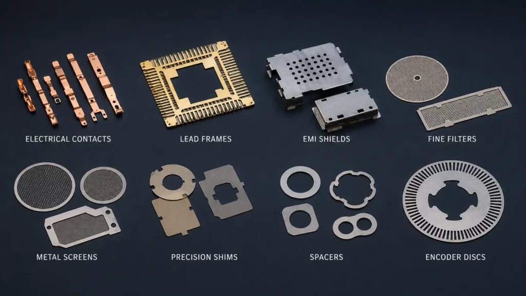
Common photo-etched products include electronic contacts, lead frames, EMI shields, filters, screens, shims, spacers, and encoder discs. Industry applications are covered separately in this guide to chemical etching applications.
What Should You Provide for a Photo Etching Project?
Send the supplier a drawing together with the material grade, thickness, critical dimensions, tolerances, quantity, surface requirements, secondary operations, inspection needs, and final application. Identify any full-etched and half-etched features clearly.
This information supports manufacturability review and identifies features that need discussion before production.
Frequently Asked Questions
Are photo etching and photochemical etching the same?
In precision metal manufacturing, photo etching, photochemical etching, and photo chemical etching usually refer to the same process. Each uses a patterned photoresist and controlled chemical removal to form metal parts.
What causes undercut in photo etching?
Undercut occurs because the etchant removes metal laterally as well as downward. Its effect depends on the material, thickness, geometry, and process conditions. Manufacturers account for it during DFM review and phototool preparation.
Can metal be photo etched from both sides?
Yes. Double-sided imaging and etching can form through-features and selected profiles. Accurate registration between the two phototools is essential.
Does photo etching produce burrs or a heat-affected zone?
Photo etching removes metal through a chemical reaction rather than a cutting tool or concentrated cutting heat. It therefore avoids conventional cutting burrs and a laser-style heat-affected zone. Edge shape still depends on thickness, undercut, and process control.
How is photo etching quality controlled?
Quality is controlled through drawing review, material verification, surface preparation, resist inspection, exposure and development checks, etchant monitoring, equipment control, and final dimensional inspection.
Conclusion
A reliable photo etching process depends on more than the etching machine. Drawing review, surface preparation, resist quality, imaging, chemistry, spray distribution, stripping, and inspection all contribute to the final result.
Before requesting production, provide the material, thickness, drawing, critical dimensions, quantity, and inspection requirements. TMNetch can review the design and identify features that may require adjustment before photo etching begins.