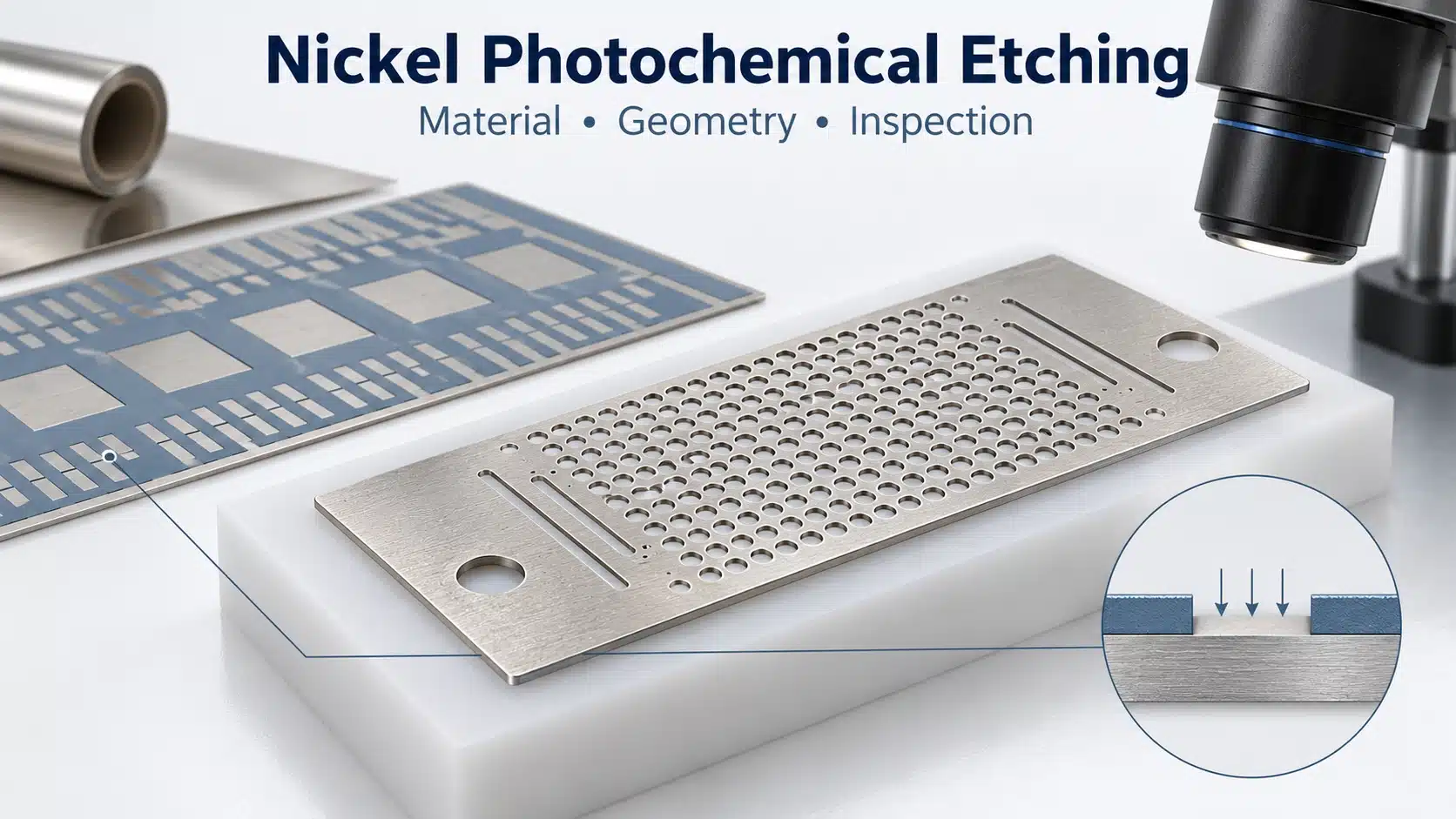

Aluminum etching, also spelled aluminium etching, removes selected areas of metal to produce openings, profiles or recessed features. A useful manufacturing review starts with four questions: which alloy and temper, what incoming surface, where metal must be removed, and how the finished part will be accepted. An alloy name and a tolerance number alone leave too much undefined.
This guide explains how to turn those questions into material specifications, process checks and drawing requirements.
Key Takeaways
- Specify alloy, temper, thickness and incoming surface together.
- Review cleaning, oxide condition, pattern integrity and etching as connected controls.
- Define critical geometry and acceptance after the agreed finishing and part-release steps.
What Is Aluminum Chemical Etching?
Chemical etching uses a controlled chemical reaction to remove metal. In photochemical machining, a patterned photoresist protects the areas that must remain while exposed metal is dissolved. Aluminum photochemical etching applies this manufacturing route to aluminum sheet or foil.
Through-etching creates openings and part outlines; partial-depth etching creates recessed features. Surface pretreatment and identification marking have different objectives and acceptance criteria. “Etched aluminum” therefore does not describe one interchangeable product.
This article focuses on reviewing functional parts. For a project centered on logos, codes or surface identification, use the aluminum laser and chemical etching comparison to clarify the required output first.
Why Is Aluminum Difficult to Etch? Oxide and Surface Condition
The starting surface needs its own specification. Aluminum carries a native oxide film, and its condition can influence the start of wet etching. That film is different from an intentionally produced anodic coating, paint, adhesive residue or rolling oil.
These conditions require separate questions. Cleaning addresses contamination; deoxidizing or activation addresses a defined surface condition. Neither term should be used as shorthand for removing every existing layer. The actual treatment sequence must be compatible with the material, resist and intended result.
For review, describe:
- Initial surface: bare, anodized, painted, coated or previously processed.
- Target surface: required appearance and functional condition.
- Allowed changes: areas that may be treated and areas that must remain protected.
If anodizing follows etching, agree the finish with the finishing supplier. Alloy, temper and pretreatment affect anodized appearance; an anodizing pretreatment guide is not a precision photoetching recipe.
Aluminum Alloy Selection for Chemical Etching
Choose the material for the component’s function, then verify the proposed etching route. The following descriptions follow the registered wrought-aluminum compositions; the review tasks are design recommendations, not an etchability ranking.
| Alloy | Material background | What to resolve before release |
|---|---|---|
| 1100 | Commercially pure aluminum | Confirm that the specified temper meets mechanical and handling requirements. |
| 3003 | An aluminum–manganese alloy | Define the supplied temper, stock form and any forming after etching. |
| 5052 | An aluminum–magnesium alloy | Review the actual sheet thickness, critical webs and final finish together. |
| 6061 | Contains magnesium and silicon among its alloying additions | Confirm stock availability in the required condition and validate the proposed geometry and finish. |
A composition designation does not establish achievable tolerance or surface quality. For example, an approval based only on “5052” leaves the temper, thickness and surface condition unresolved.
Use one material submission rule: grade + temper + stock form + thickness + surface condition + functional requirements. Request the relevant material certificate and condition-specific property data when those properties control the application.
Aluminum Chemical Etching Process: Step-by-Step
The four stages below group the standard photochemical machining sequence into review checkpoints. They are not four universal machine operations. For the broader production workflow, see the chemical etching process guide.
Step 1: Cleaning and Surface Preparation
Before resist application, the sheet is cleaned to support adhesion. For aluminum, also identify the oxide or coating condition and determine what preparation the qualified process requires.
At this checkpoint, ask whether the incoming sheet matches the approved material and surface specification. Keep a record of pre-existing stains, scratches or coated areas so that later observations can be compared with the starting material.
Step 2: Photoresist, Imaging and Pattern Verification
Photoresist application, exposure and development establish the protective pattern. When both faces carry a pattern, include their alignment in the review.
Check pattern continuity, intended openings and resist integrity before metal removal. Exposure and development settings belong to a validated material and equipment combination; “increase UV” is not a complete corrective action. Record which pattern revision and processing conditions produced the accepted image.
Step 3: Controlled Etching and Solution Selection
An aluminum etching solution must suit both the metal-removal task and the masking system. Etchant–photoresist compatibility matters: some alkaline aluminum etchants can dissolve or lift conventional photoresist masks.
For selecting etchants for aluminum, review the alloy, required removal, target profile and surface acceptance together. Experimental aluminum etching research examines etch depth and surface roughness under specified conditions. Such results support evaluating both outcomes; they do not establish a universal production recipe.
Step 4: Resist Stripping, Cleaning and Inspection
After etching, the resist is stripped and the part is cleaned and inspected. Specify any subsequent finishing separately.
The checkpoint here is the etched condition: does the geometry meet its interim requirements, and is the part ready for the next operation? Final acceptance must still address the agreed delivered condition.
Common Aluminum Etching Defects: Causes and Checks
Treat an unexpected result as an investigation, starting with evidence. A visible symptom does not establish its cause.
For example, in aluminum microstructuring, development can alter local oxide conditions and the start of etching. Uneven removal therefore warrants reviewing the preceding patterning stages as well as the etching stage. This is a possible mechanism, not a diagnosis for every aluminum part.
| Observation | First checks | Evidence to compare |
|---|---|---|
| Uneven removal or unetched patches | Incoming surface, preparation and developed pattern | Before/after images and mapped depth or thickness readings |
| Gray residue or discoloration | When the change first appeared | Images before and after cleaning and finishing, plus process records |
| Isolated pits or unintended removal | Starting surface and resist integrity at the same locations | Microscopy, defect-location maps and other pieces from the batch |
| Oversized openings or narrow webs | Artwork revision, compensation and measurement definition | Approved drawing, phototool data and measurements at agreed locations |
| Missing or incomplete pattern boundaries | Resist application, imaging and development records | Pattern images before etching and corresponding finished features |
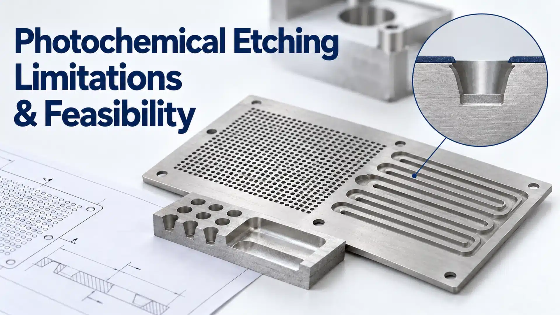
These are suggested checks, not confirmed cause-and-effect relationships. Preserve material identity and drawing revision throughout the investigation. For the broader geometric mechanisms, see the limitations of photochemical etching.
Design Guidelines for Etched Aluminum Parts
An effective DFM review connects each requirement to a feature and an acceptance method. Start with what controls assembly or performance.
Define the Material, Thickness and Critical Geometry
Identify locating holes, slots, minimum webs, hole spacing and repeated patterns. Explain whether function depends on one aperture, the relationship between several features, or the full patterned area.
Etching removes metal laterally as well as through the thickness. Consequently, a narrow opening and its neighboring web should be reviewed together with sheet thickness. A top-view outline alone does not fully describe the resulting edge profile.
Define the measurement face, location and datum for critical features. Reserve tighter tolerances for requirements that need them; discuss the remaining dimensions against the proposed process capability. General ratios and tolerance tables are starting points, not project approval.
Specify Partial-Depth Features, Edges and Release Condition
For a recess, identify the face to be etched, its location, and the required depth or remaining metal thickness. State which quantity controls function and how it will be verified.
Call out important corner and edge requirements. If a perpendicular wall is essential, request cross-section evidence during feasibility review. Also specify whether delivery is in a carrier sheet, with retaining tabs, or as separated parts, including permitted tab locations and removal marks.
Include Surface, Flatness and Final-Finish Requirements
Mark functional and cosmetic surfaces. Define acceptable appearance through an agreed specification or reference sample rather than “good surface quality.” For flatness, agree the delivery state and measurement support conditions.
For anodized parts, define controlled dimensions in the agreed finished state. Anodizing does not hide underlying surface texture or defects, so resolve appearance expectations before approving the manufacturing route.
| Component function | Drawing priority | Verification question |
|---|---|---|
| Perforated screen | Clear openings and remaining webs | Where is each width measured? |
| Shim or gasket | Thickness, seating area and profile | Which condition controls assembly? |
| Recessed feature | Depth or remaining metal | Which locations require depth measurement? |
Illustrative DFM example: Consider a 5052 sheet component with two locating holes, a ventilation array and a planned anodized finish. The review should separate hole-position requirements from the ventilation openings, identify minimum remaining webs, and define flatness after part separation and finishing. The supplier can then assess these specific requirements instead of interpreting one tight general tolerance across the drawing. This is a design example, not a reported customer project.
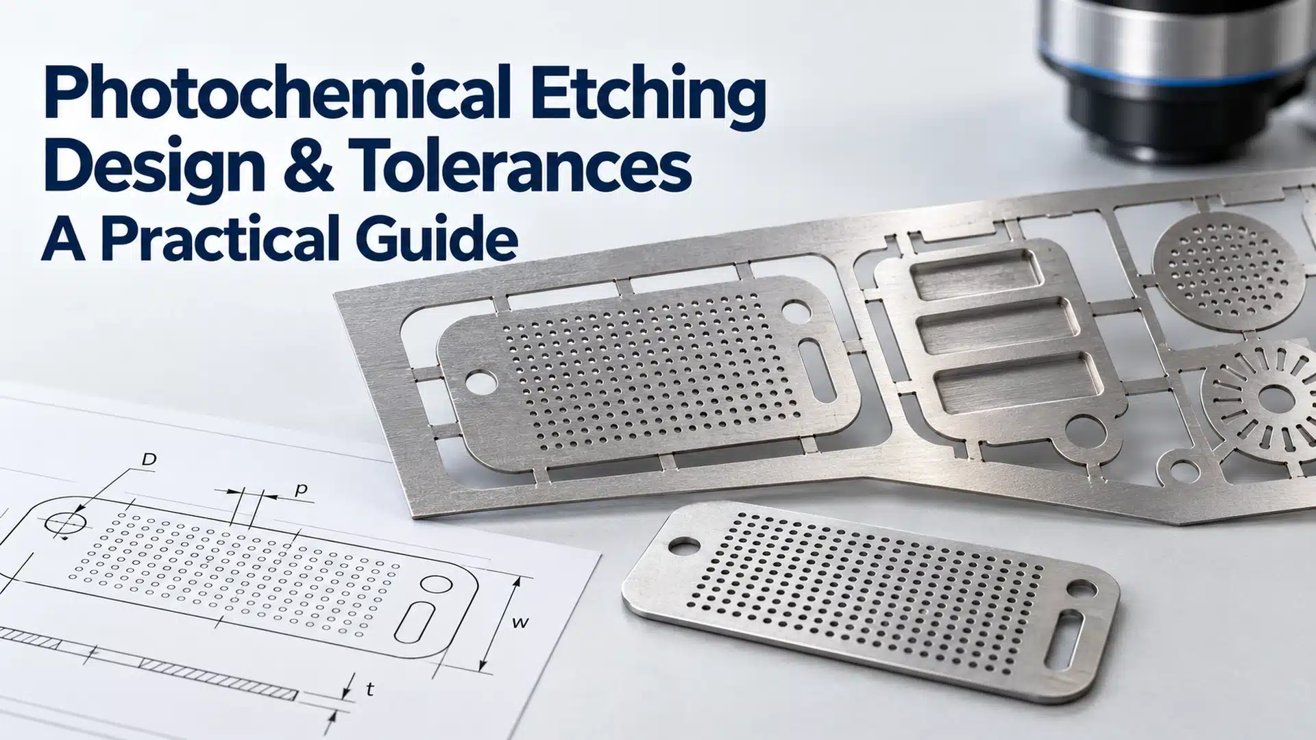
Use the design and tolerance guide for broader feature-design guidance.
Inspect the Part After Etching and Finishing
Inspection should answer the drawing’s questions in the agreed delivery state. Select dimensional measurement equipment around the design and measurement requirements, including the uncertainty needed to make an acceptance decision.
| Inspection object | Define before measurement |
|---|---|
| Openings, webs and profile | Measurement face, location, datum and limits |
| Partial-depth features | Depth or remaining thickness, reference surface and measurement locations |
| Surface and cleanliness | Separate appearance, residue and functional requirements |
| Flatness and release condition | Support conditions and whether parts are attached or separated |
| Finished part | Required checks after anodizing, coating or other agreed operations |
A top-view image does not by itself verify recess depth. Likewise, an inspection before finishing cannot substitute for a requirement specified after finishing. Agree the method, acceptance limits and inspection records before approving the production sample.
Aluminum Chemical Etching FAQs
How is aluminum chemically etched?
The process combines surface preparation, resist patterning, controlled chemical removal, stripping, cleaning and inspection. The four stages above explain what to verify at each checkpoint.
Which aluminum alloy should I specify for an etched part?
Choose for the component’s function, then review the grade, temper, stock form, thickness and finish with the supplier. The alloy table is a submission guide, not a ranking of easiest materials.
Which etching solution is used for aluminum?
There is no single best solution for every project. Specify the required output and ask the supplier to confirm a compatible, validated etching and masking system.
Can anodized or coated aluminum be etched?
Feasibility requires defining whether the target is the coating, the aluminum beneath it or the complete part geometry. Identify surfaces that must remain intact before selecting a route.
What tolerances can aluminum etching achieve?
Request confirmation for the actual material, thickness, geometry, measurement location and finished state. Use numerical capability claims only with their applicable conditions and supporting inspection evidence.
What to Send for an Aluminum Etching Review
Before requesting a quotation, assemble:
- The drawing, revision and available CAD data.
- Alloy, temper, stock form, thickness and incoming surface condition.
- Critical geometry, recess requirements and protected areas.
- Surface finish, flatness and final inspection requirements.
- Prototype and production quantities, plus the required delivery form.
Send these inputs for an aluminum etching review with TMNetch. Resolve open material and acceptance questions before freezing the drawing, so the quotation and sample review address the same requirements.