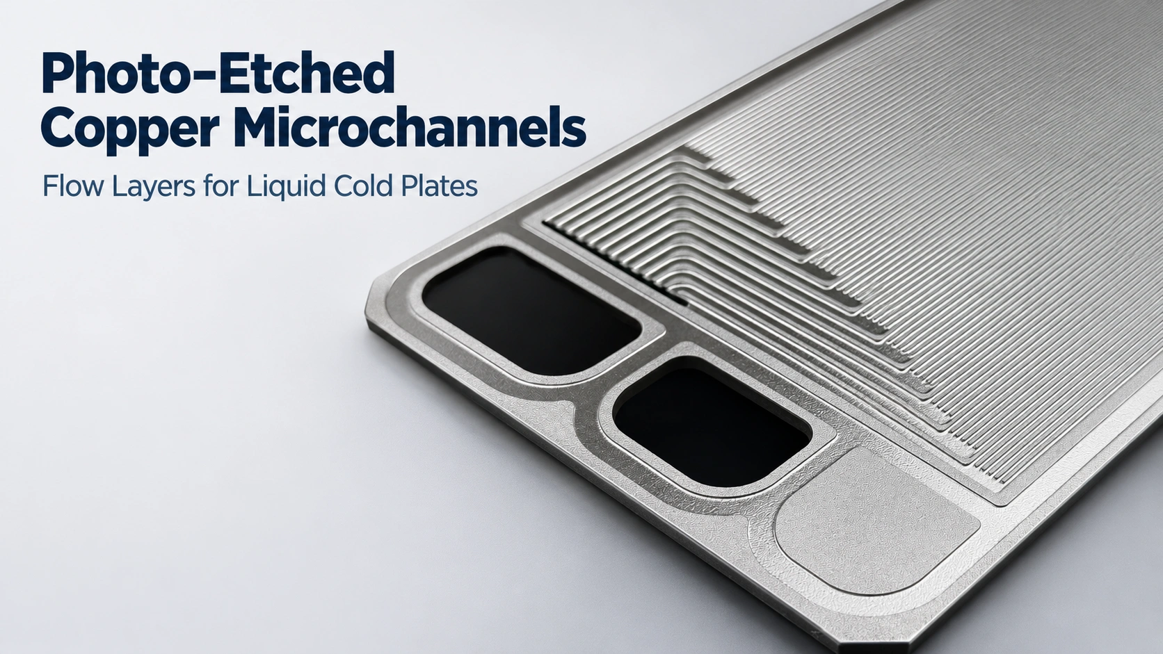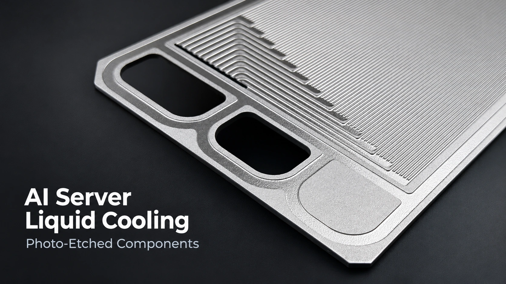

A copper flow-layer drawing may specify shallow microchannels, inlet ports, alignment holes, and narrow metal sections between adjacent passages. Before choosing photochemical etching, an OEM needs to know whether these features can be manufactured and inspected—and whether the finished plate will meet the requirements of the next assembly process.
For AI server liquid cooling, photo-etching is a candidate for selected thin copper layers with complex, closely spaced flow patterns. It is not necessarily the right process for a thick cold plate base or deep three-dimensional cavities.
This guide focuses on two engineering decisions: how to evaluate a copper flow-layer drawing for etching, and what evidence should accompany the part when it is delivered for joining.
Quick Answer: When Is Photo-Etching Suitable for a Copper Cold Plate?
Photo-etching is worth considering when a liquid cold plate design uses thin copper sheets containing shallow channels, distribution recesses, through-holes, or alignment features.
Before requesting a quote, check five things:
- Material: Exact copper grade, condition, and sheet thickness.
- Channel geometry: Opening width, depth, pitch, undercut allowance, and minimum metal remaining.
- Joining interface: Required bonding-land width, flatness, and surface condition.
- Inspection: Measurement datums, critical dimensions, and acceptance limits.
- Assembly handoff: The records and part condition required by the joining supplier.
A typical development route is:
Copper Sheet → Photo-Etching → Flow-Layer Inspection → Supplier Handoff → Alignment and Joining → Cold Plate Qualification
The manufacturing principles used for etched microchannel heat exchangers provide a useful starting point, but the dimensions and acceptance criteria must be established for the specific cold plate design.
Choosing a Manufacturing Method: Start with the Channel Geometry
Copper cold plates can contain machined grooves, skived fins, formed fins, or stacked flow layers. These features may perform similar cooling functions, but they are manufactured differently.
The first comparison should therefore be how the flow passages or heat-transfer surfaces are formed, rather than how the finished cold plate is sealed.
| Flow-Feature Manufacturing Method | Best-Fit Geometry | Main Drawing Considerations |
|---|---|---|
| CNC Micro-Milling | Deep channels in a thick copper base; complex machined cavities | Tool access, groove depth, internal corners, burr control |
| Skiving | Regular, closely spaced fins formed from a solid metal base | Fin thickness, pitch, height, and layout |
| Photochemical Etching | Shallow, patterned channels and openings in suitable thin sheets | Etch depth, undercut, minimum ligament, remaining wall, bonding lands |
CNC milling is a practical choice when the drawing requires significant material removal from a thick base or when mechanical features need three-dimensional machining.
Skiving takes a different approach. A controlled cutting tool lifts thin sections of the parent metal to form fins that remain connected to the base. This construction is used in high-performance liquid cold plates, as demonstrated by skived copper cold plate manufacturing.
Photochemical etching becomes relevant when the geometry is primarily planar and includes many repeated or branching features. It can create partial-depth recesses and selected through-openings without machining each passage individually.
Other designs use separately formed fins, which may be attached to the cold plate body during a subsequent joining operation.
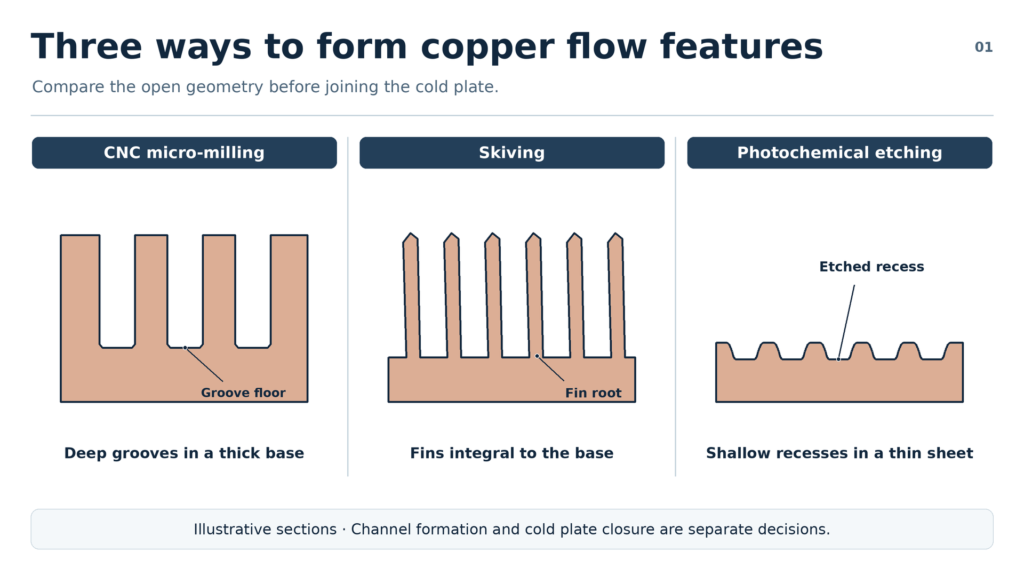
Channel formation and cold plate closure are separate manufacturing decisions.
Once the internal geometry has been selected, the designer must determine how the passages will be enclosed. Depending on the construction, this may involve brazing, diffusion bonding, welding, or another qualified joining method.
The preferred route depends on both the feature geometry and the intended assembly, rather than a universal ranking of manufacturing processes. For a broader process-selection framework, see chemical etching vs. laser cutting, stamping, CNC and other manufacturing methods.
How to Evaluate a Copper Microchannel Drawing for Etching
A flow-layer drawing should allow the manufacturer to determine what metal must be removed, what metal must remain, and how the finished geometry will be verified.
A useful review starts with the material and then moves to the channel cross-section.
1. Confirm the Copper Grade and Starting Thickness
Specify the copper grade, material condition, nominal thickness, and thickness tolerance.
The material specification matters because photo-etching behavior and downstream joining requirements depend on the starting material and its condition.
The sheet thickness also establishes the available depth for partial etching.
For a layered cold plate, the drawing should identify whether the specified thickness applies to the incoming copper sheet or to the finished etched component.
The joining supplier should also confirm whether it requires a particular surface condition or additional material preparation before assembly.
2. Define the Channel Cross-Section and Measurement Locations
A wet-etched channel is not necessarily rectangular.
As the chemical process removes exposed metal, material can also be removed laterally beneath the resist pattern. This effect, known as undercut, changes the relationship between the mask opening and the finished channel.
Copper photochemical machining research establishes that etchant conditions and processing time can influence material removal, undercut, and surface quality.
For this reason, a drawing that specifies only “channel width” may be incomplete. Before assigning acceptance limits, review the photochemical etching tolerance and design guide for thickness-dependent feature relationships and measurement considerations.
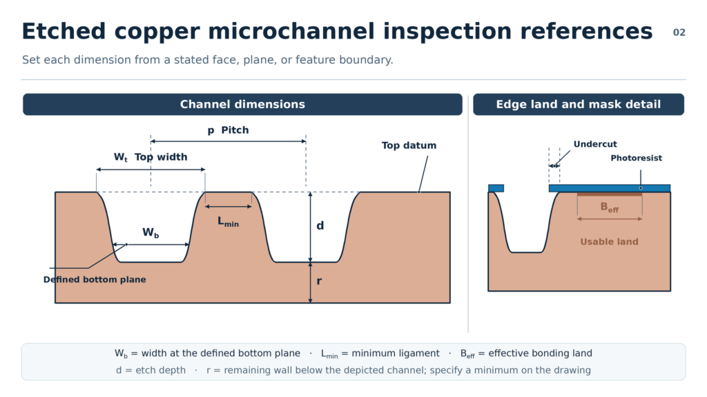
The drawing should identify the following dimensions and their measurement references:
| Dimension | Drawing Definition |
|---|---|
| Wt – Top Width | Channel width measured at the specified original top-surface datum |
| Wb – Bottom Width | Channel width measured at a defined depth or bottom measurement plane |
| d – Etch Depth | Distance from the specified top datum to the deepest channel surface |
| p – Channel Pitch | Defined spacing between adjacent channel centerlines |
| Lmin – Minimum Ligament | Narrowest permitted metal section between adjacent channels |
| Beff – Effective Bonding Land | Minimum usable joining width after accounting for adjacent features and alignment requirements |
| rmin – Minimum Remaining Wall | Minimum material thickness beneath the deepest etched feature |
Figure 1. Etched copper microchannel cross-section and inspection references
The cross-section should show the original top-surface datum, channel opening, bottom measurement plane, minimum ligament, effective bonding land, and remaining wall.
Top width and bottom width must each have a defined measurement location.
A single bottom-width value does not describe the entire channel profile. Rounded corners, curved sidewalls, and local profile variation may require an additional cross-sectional measurement or an agreed profile envelope.
Likewise, effective bonding-land width should be defined with the intended joining supplier. The visible flat area on an etched plate is not automatically the entire usable joining area.
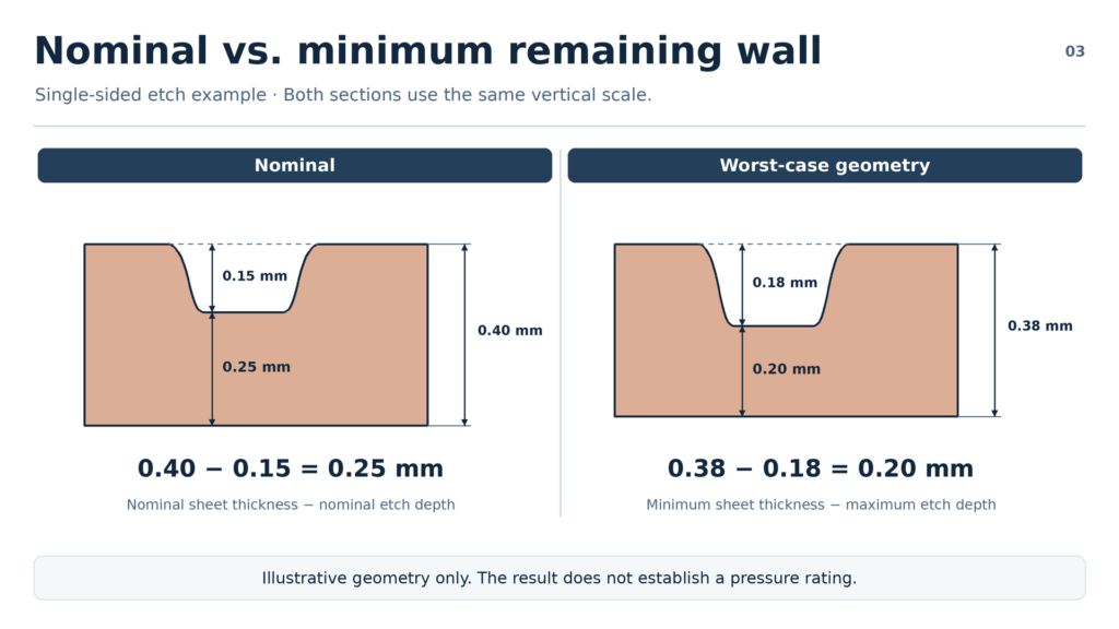
3. Check the Minimum Remaining Wall Using Worst-Case Dimensions
For a channel etched from one side of a copper sheet, the nominal geometric relationship is:
Remaining Wall Thickness = Sheet Thickness − Etch Depth
However, using nominal dimensions alone can overlook the combined effect of manufacturing tolerances.
For a conservative geometric check, use:
Minimum Remaining Wall = Minimum Permitted Sheet Thickness − Maximum Permitted Etch Depth
Consider an illustrative drawing specifying:
- Copper sheet thickness: 0.40 ± 0.02 mm
- Etch depth: 0.15 mm, with +0.03 / −0.02 mm tolerance
The minimum permitted sheet thickness is 0.38 mm, and the maximum permitted etch depth is 0.18 mm.
Therefore:
rmin = 0.38 − 0.18 = 0.20 mm
This gives a worst-case geometric remaining wall of 0.20 mm, assuming the thickness and depth values share the specified measurement references.
The numbers are illustrative, not published TMNetch capability limits.
A geometric remaining-wall calculation does not establish whether the wall can withstand the cold plate’s operating pressure. Structural requirements must be evaluated using the complete component geometry, material properties, and joined assembly design.
For further guidance on thickness-dependent features, see etched heat exchanger plate thickness and design considerations.
4. Review Bonding Lands, Ports, and Layer Alignment
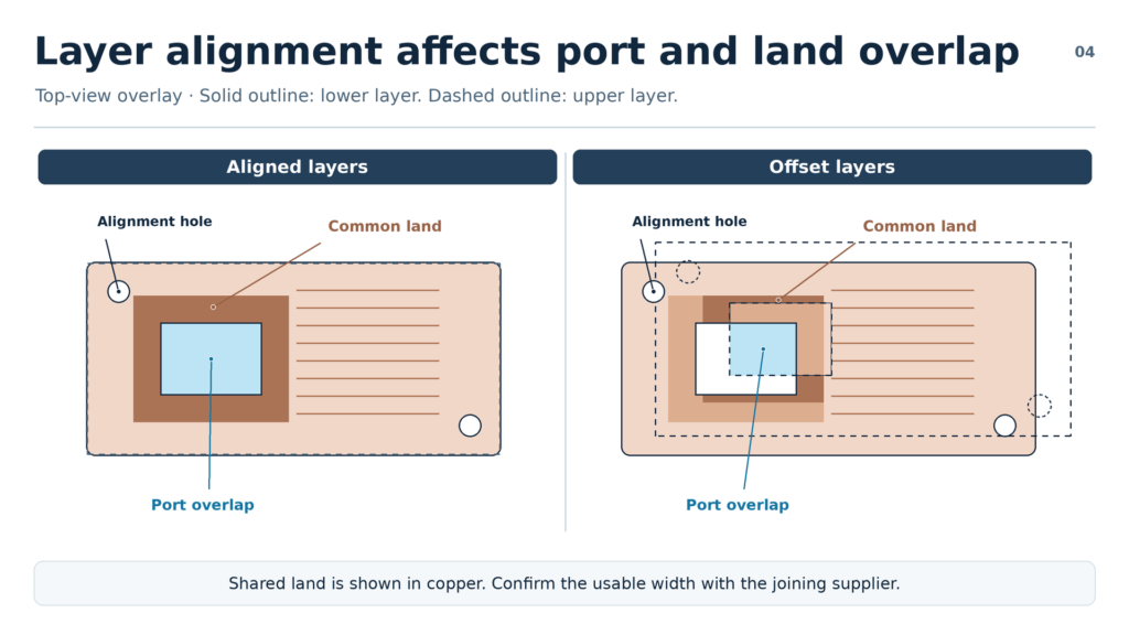
Channel geometry must be evaluated together with the areas that will connect the etched plate to adjacent layers.
The drawing should show where material must remain for joining, along with inlet and outlet ports, alignment holes, and their positional tolerances.
The joining supplier should define the minimum effective bonding land, acceptable surface condition, and registration requirements.
This matters because an etched plate can meet its individual channel dimensions but still be unsuitable for assembly if the joining lands are too narrow or if corresponding ports do not align.
The designer should also establish whether the critical dimensions apply before joining, after joining, or at both stages.
That distinction determines which supplier can verify each requirement.
From Flat Copper Sheet to an Accepted Etched Flow Layer
Once the drawing is suitable for etching, manufacturing can proceed through material preparation, photoresist patterning, chemical removal, cleaning, and inspection.
In the chemical etching process, a patterned photoresist protects selected regions while exposed metal is removed chemically.
Partial-depth etching produces recessed features. Through-etching can produce suitable openings and external profiles.
The finished part should then be inspected against the drawing revision and its agreed acceptance criteria.
For a copper microchannel layer, dimensional inspection should focus on the features that influence the next manufacturing stage:
- Channel widths at the specified measurement locations
- Etch depth and remaining wall thickness
- Minimum ligaments and effective bonding lands
- Port dimensions and positional alignment
- Flatness, surface condition, and cleanliness
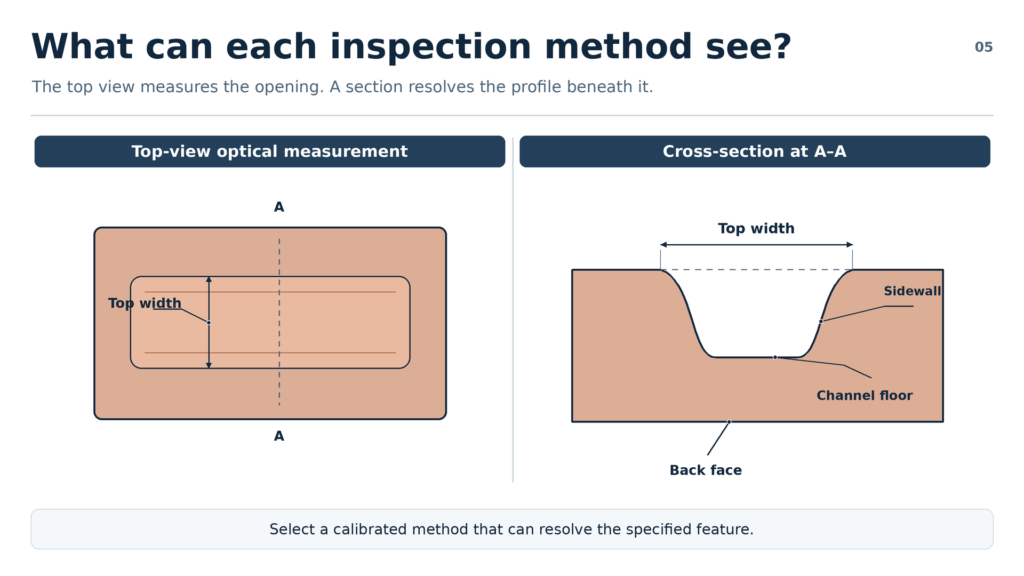
The appropriate measurement method depends on feature accessibility, size, geometry, and required uncertainty. Cross-sectional inspection, optical measurement, profilometry, or other calibrated techniques may be selected for particular characteristics.
For example, a surface measurement may confirm an opening width, but a full channel profile requires a method capable of measuring the relevant cross-section.
An inspection report should identify the drawing revision, measurement method, measurement location, and acceptance limits rather than reporting an unexplained dimension.
Related inspection considerations are covered in quality inspection for etched heat exchanger components.
What Must Be Delivered to the Cold Plate Joining Supplier?
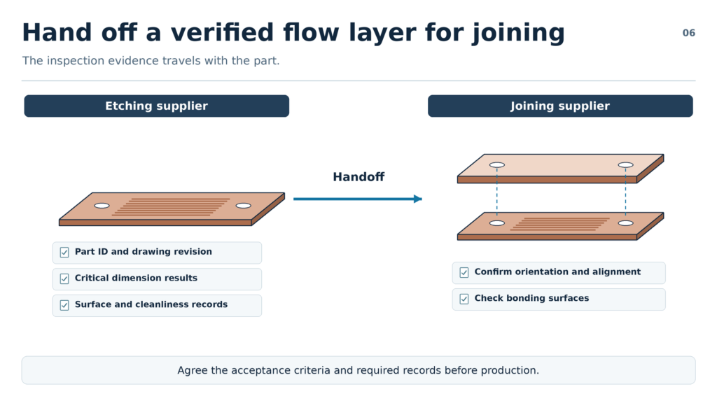
This is the main handoff point between component fabrication and cold plate assembly.
The joining supplier needs more than a plate that appears visually correct. It needs evidence that the etched geometry and surface condition are compatible with the agreed assembly process.
The following table combines manufacturing responsibility with the expected deliverables.
| Manufacturing Stage | Responsible Party | Required Deliverable or Acceptance Evidence |
|---|---|---|
| Drawing Review and DFM | OEM and etching supplier | Approved drawing revision, material specification, agreed critical dimensions and inspection plan |
| Photo-Etching | TMNetch, subject to confirmed capability | Etched copper flow layers identified to the approved part revision |
| Etched-Part Inspection | TMNetch, within the agreed supply scope | Dimensional results, relevant profile or depth measurements, surface and cleanliness records as specified |
| Handoff to Joining Supplier | Etching supplier and receiving assembler | Part identification, traceability records, material documentation where required, orientation and handling instructions, acceptance status |
| Layer Alignment and Joining | Qualified joining/assembly supplier | Assembly records, joining-process records, alignment verification, and applicable post-joining inspection |
| Cold Plate Qualification | Responsible cold plate OEM or qualified testing provider | Leakage, pressure, flow, thermal, and reliability test results required by the product specification |
The scope of supplied records must be agreed before manufacturing. Material certificates, full profile maps, or specific cleanliness tests should not be assumed to be included unless required by the project.
For the joining supplier, three handoff questions are particularly important.
Are the flow features within the approved dimensional envelope? The inspection evidence should correspond to the dimensions and datums used in the assembly drawing.
Are the joining surfaces suitable for the selected process? The assembler must verify the relevant flatness, surface condition, and preparation requirements.
Can each part be traced to its material, drawing revision, and inspection status? This allows discrepancies found during assembly to be investigated against the correct production records.
A clean handoff helps separate a flow-layer fabrication issue from a subsequent alignment or joining issue.
After Joining: How Is the Completed Cold Plate Qualified?
Once the metal layers are joined, inspection must address features that cannot be fully evaluated from the original open plate.
The OCP Single-Phase Direct-to-Chip Cold Plate Test Specification V1.0.0, effective September 3, 2026, provides a common framework for design and prototype qualification of single-phase direct-to-chip cold plates.
Its tests address different failure modes and performance requirements.
Leak detection checks whether fluid or test gas can escape through unintended paths. Tracer-gas methods can help identify small leaks.
Pressure decay and hydrostatic pressure dwell evaluate leakage and structural behavior while the assembled cold plate is held under specified test conditions.
Burst-pressure testing evaluates structural pressure capacity under a defined destructive or limiting test procedure. It is different from a routine leak check.
Pressure-drop testing determines the hydraulic resistance of the cold plate at specified flow rates, accounting for the test-loop contribution.
Thermal-resistance testing evaluates heat-transfer performance under controlled heat input, coolant conditions, and measurement locations.
These tests cannot replace one another. A plate may be leak-tight yet fail to meet its specified pressure-drop or thermal-resistance target.
Thermal Resistance: Define the Temperature Measurement Point
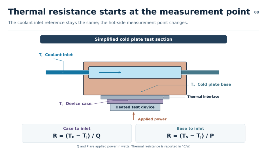
Two thermal-resistance definitions appear in OCP cold plate documentation. Their measurement boundaries should not be confused.
The earlier Cold Plate Development and Qualification white paper uses:
Rcase-to-inlet = (Tc − Tl) / Q
Where:
- Tc: Case temperature of the heat-generating component
- Tl: Coolant temperature at the cold plate inlet
- Q: Applied power
This describes a case-to-inlet thermal-resistance measurement for the defined test arrangement.
The 2026 Single-Phase Direct-to-Chip Cold Plate Test Specification uses:
Rbase-to-inlet = (Ts − Tl) / P
Where:
- Ts: Cold plate sink or base temperature at the specified measurement location
- Tl: Coolant inlet temperature
- P: Applied power
The newer measurement therefore uses the cold plate base temperature rather than automatically substituting the device case temperature.
Because the temperature locations differ, results calculated using these two definitions should not be compared directly without accounting for the different measurement boundaries.
Coolant flow, inlet temperature, thermal interface conditions, and power measurement must also be reported consistently.
Importantly, OCP V1.0.0 covers design and prototype qualification. Production sampling plans, in-line screening, and factory acceptance limits are outside its stated scope and must be established separately for the project.
TMNetch Case: Hybrid Processing of Metal Flow Plates
TMNetch has documented a flow-plate project combining chemical etching and laser cutting, involving 316 stainless steel and titanium.
The project illustrates how fine flow features and larger structural cuts can be assigned to different processes according to the part geometry.
It is not a documented copper cold plate or AI server cooling assembly. Its relevance to this article is the feature-by-feature manufacturing review, rather than proof of completed copper cold plate qualification.
For a future copper flow-layer project, stronger manufacturing evidence would include an attributable sample photograph, verified copper grade and sheet thickness, a measured channel cross-section, the inspection method, and the associated acceptance criteria.
Such evidence should be published only after the project information has been verified and approved for disclosure.
What Should an OEM Send for a Copper Flow-Layer DFM Review?
An initial RFQ does not need to contain a complete cold plate qualification report. It should, however, define the component clearly enough for a supplier to evaluate manufacturing feasibility.
Send the approved or preliminary CAD drawing together with the copper grade, material condition, and sheet thickness.
Identify the partial-depth channels, through-openings, and critical features. State the required channel dimensions, maximum etch depth, minimum remaining wall, ligament width, and joining-land requirements.
Also provide the intended joining method, inspection requirements, prototype quantity, and expected production volume.
Where a dimension is still under development, identify it as preliminary and state which changes the designer can accept.
The first manufacturing decision is whether the copper layer can be produced and inspected to an agreed specification—not whether the complete cold plate has already achieved its final cooling performance.
TMNetch’s copper etching service provides a starting point for discussing suitable materials, flow-layer geometry, and prototype feasibility.
Frequently Asked Questions
How can internal channel dimensions be verified after diffusion bonding?
After joining, the channels may no longer be directly accessible. Depending on the material, geometry, and required resolution, a qualified inspection plan may use X-ray or CT methods, destructive cross-sections of representative samples, or other validated methods.
The selected method must be capable of detecting the relevant feature or defect. Inspection before joining remains important because not every internal dimension can be measured directly after assembly.
Is specifying channel width and depth enough for an etched copper flow layer?
Not always. The drawing should identify where channel width is measured and define the permitted cross-sectional profile where relevant.
Remaining wall thickness, minimum ligament width, and joining-land requirements may also be critical. A nominal opening width does not fully describe undercut or the shape of the channel below the surface.
Can the same dimensional tolerances be used before and after joining?
Only if the design and joining process support that requirement.
Alignment, joining temperature, applied pressure, and process-related dimensional changes can affect the finished assembly. The OEM should distinguish dimensions verified on the etched plate from dimensions that must be verified after joining.
Conclusion: Qualify the Flow Layer Before the Cold Plate Assembly
For a copper microchannel cold plate, the first manufacturing decision is how to create the required internal geometry.
CNC milling suits many thick-base and deep-channel designs. Skiving is suited to selected regular fin structures. Photochemical etching is worth evaluating for thin copper layers containing intricate shallow channels and distribution features.
The value of an etched flow layer depends not only on whether its pattern can be produced, but also on whether its critical dimensions, joining surfaces, and inspection records are suitable for the next manufacturing stage.
A drawing with defined datums, worst-case remaining-wall requirements, and a clear inspection plan gives the etching supplier and joining supplier a shared basis for acceptance.
Need a Photochemical Etching Review for a Copper Flow Layer?
TMNetch provides custom copper photochemical etching services for precision metal components.
Submit your copper grade, sheet thickness, channel drawing, critical dimensions, and inspection requirements to discuss flow-layer manufacturability and prototype options.