
PEM electrolyzer stack manufacturing involves more than placing a membrane between two plates. Stack performance depends on controlled interfaces between the catalyst-coated membrane (CCM), porous transport layers (PTLs), plate structures, seals, and compression hardware. A qualified component can still fail after assembly if alignment, surface condition, or contact pressure is wrong.
A reliable process starts with operating requirements, then links material inspection, fabrication, surface treatment, clean assembly, compression, and end-of-line testing. This guide focuses on PEM electrolyzer stacks and their critical components. Balance-of-plant integration appears only as a downstream interface. For the electrochemical reactions, see how a PEM electrolyzer works.
Key Takeaways
- Manufacturing requirements must be defined before choosing a plate, PTL, or CCM process.
- Porous-layer names vary by architecture; confirm the term and function against the stack drawing.
- Plate production must balance corrosion resistance, conductivity, geometry, and cost.
- CCM control starts with ink dispersion and includes loading and defect inspection.
- Alignment, cleanliness, sealing, and compression determine whether qualified parts work together.
- Bolt torque alone does not prove uniform contact pressure across the active area.
- Quality control must cover incoming materials, in-process CTQs, and assembled-stack performance.
- Prototype routes should support learning; mass-production routes must control capability, yield, and traceability.
PEM Electrolyzer Manufacturing Process at a Glance
The manufacturing chain can be summarized as:
Engineering requirements → Incoming materials → Plate structures → PTLs → CCMs → Frames and seals → Cell assembly → Stack compression → Stack testing → Production release
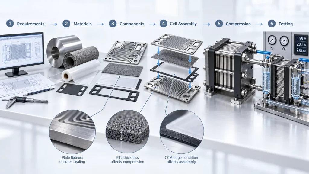
These stages are interdependent. Plate flatness affects sealing, PTL thickness affects compression, and CCM edge condition affects handling. Any component change may require new assembly settings or validation limits.
For a functional overview of the parts referenced below, see PEM electrolyzer components.
Define PEM Electrolyzer Manufacturing Requirements First
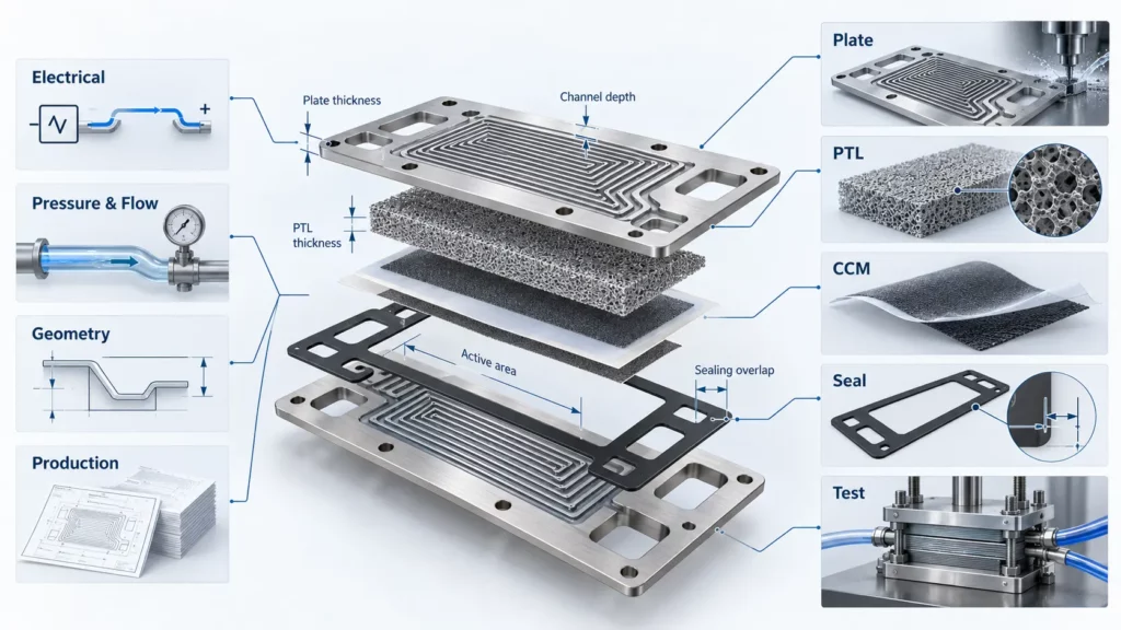
Start with stack duty, not a preferred production method. Translate system requirements into measurable component and interface CTQs.
| Requirement group | Inputs to define before production |
|---|---|
| Electrical | Design current density, active area, operating voltage, cell count |
| Pressure and flow | Hydrogen pressure, water/oxygen-side pressure, differential pressure, flow rate |
| Geometry | Plate and PTL thickness, flow field, sealing lands, ports, alignment features |
| Production | Prototype quantity, annual volume, target yield, traceability, inspection level |
These inputs determine material, tooling, coating, assembly, and testing. They also set the required cycle time, inspection throughput, and yield.
Manufacturing route selection should follow component function, operating environment, and production volume.
Incoming Material Preparation and Inspection
Incoming inspection prevents material variation from becoming a hidden process variable. Confirm identity, certificate data, thickness, surface condition, contamination, and lot traceability. Verify porous structure by an agreed method.
Plate materials
PEM electrolyzer plates may use titanium, coated metallic substrates, or selected stainless-steel concepts. Material choice affects forming, etching, cleaning, coating, welding, inspection, and corrosion control. Approve the manufactured surface, not bulk material data alone.
PTL materials
The anode PTL handles water feed and oxygen removal. Options include titanium felt, mesh, sintered powder, and engineered porous structures. Titanium resists the anode environment, but its surface can raise contact resistance.
Membrane and catalyst materials
In many low-temperature PEMWE designs, the CCM uses a proton-conducting membrane with an Ir-based oxygen-evolution catalyst on the anode and a Pt-based hydrogen-evolution catalyst on the cathode. Catalyst loading, ionomer content, membrane thickness, and coating route remain design-specific. Control material identity, storage, shelf life, contamination, and lot traceability.
Flow-Field, Separator, and Bipolar Plate Manufacturing
Plate production controls two outputs: flow-field geometry and the final surface presented to the PTL and seal.
In PEM water electrolyzers, the terms bipolar plate, separator plate, flow-field plate, and current-collector plate may describe different functions depending on stack architecture. Confirm the exact terminology and function against the stack drawing. In this guide, “plate” refers collectively to these metallic flow-distribution and current-collection structures.
Sheet preparation
Verify sheet identity, thickness, cleanliness, and flatness before channel formation. Blank size and datums must support port and stack alignment.
Flow-field formation
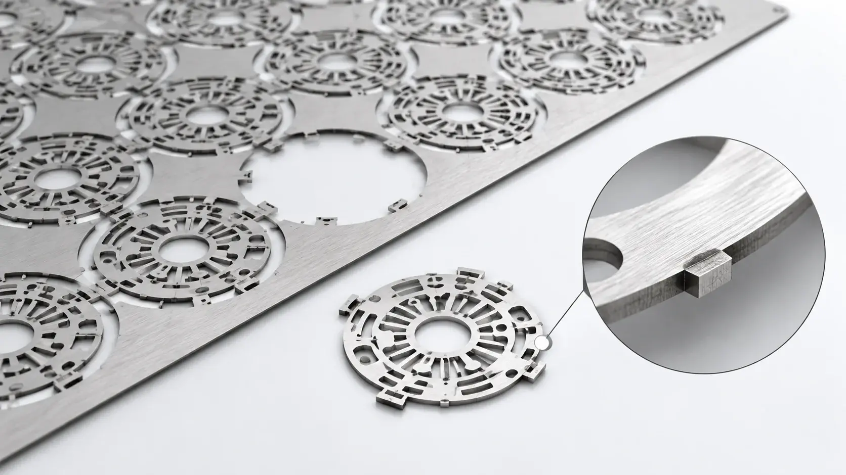
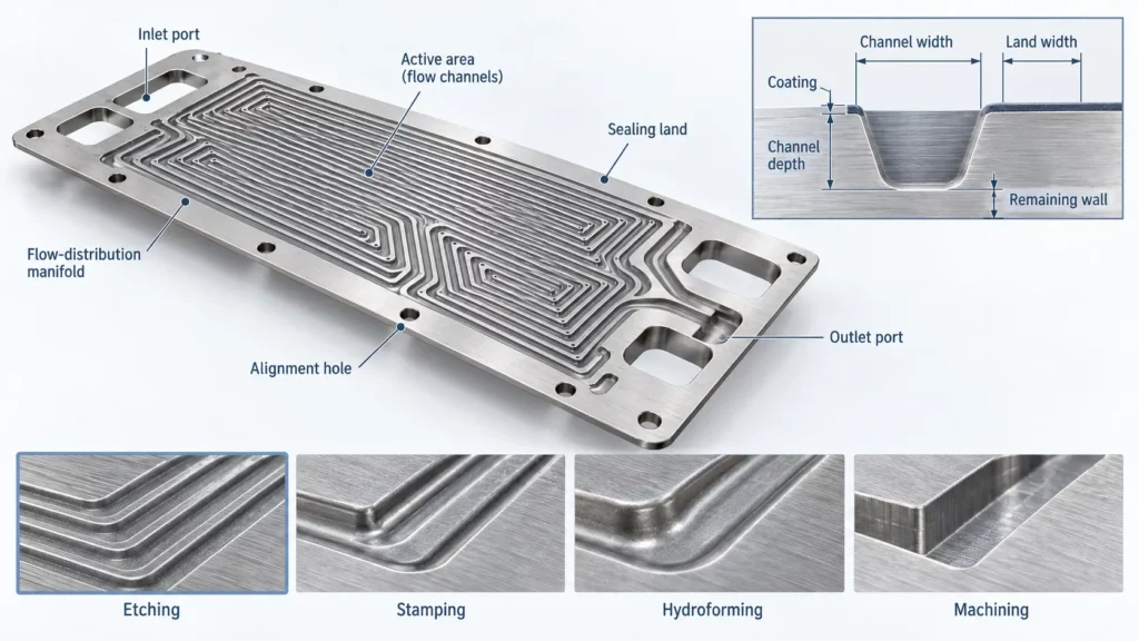
Metal flow fields can be etched, stamped, hydroformed, or machined. Select by thickness, channel depth, complexity, tolerance, tooling, and volume. See this comparison of bipolar plate manufacturing processes.
Chemical etching suits thin plates, complex channels, and frequent revisions because it needs no hard forming tool. Stamping and hydroforming support higher volume after design release. Machining suits thicker development hardware but may restrict throughput and tool access.
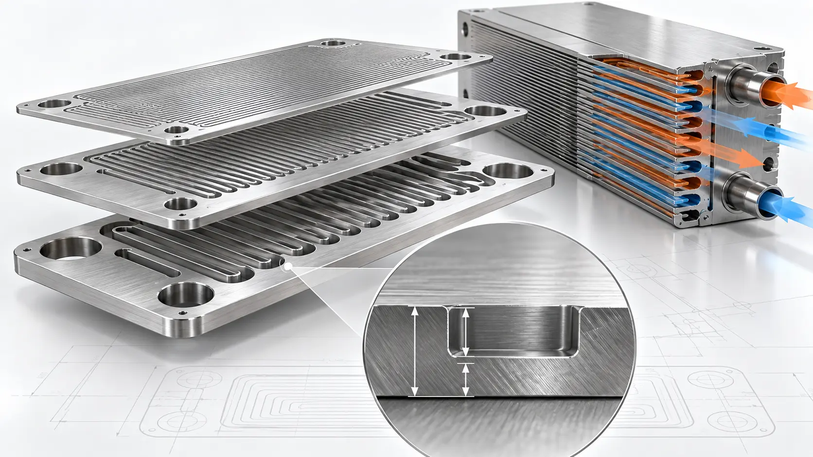
For prototype or low-volume work, chemically etched flow-field plates can support rapid CAD revision. The drawing must still define channels, lands, flatness, ports, and inspection.
Critical plate dimensions
Control channel depth and width, land width, ports, transition geometry, alignment holes, sealing lands, and flatness. Channel error affects flow; land and flatness errors affect contact and sealing.
Cleaning and surface preparation
Remove oil, process residue, particles, and loose oxide as required. Inspect before coating because coating cannot correct contaminated or inaccurate geometry. See how etched plate surface quality affects coverage.
Surface treatment and coating
Improve corrosion resistance without excessive interfacial contact resistance. Control surface preparation, coverage, adhesion, uniformity, edges, and pinholes. Match acceptance methods to the coating and PEMWE environment.
Plate inspection
Check thickness, flow-field geometry, ports, flatness, surface defects, coating, and alignment. Visual acceptance alone does not prove dimensional or electrical performance.
Porous Transport Layer Manufacturing
In PEM water electrolyzers, the porous layer is commonly called a porous transport layer (PTL). The terms porous transport electrode and gas diffusion layer may also appear in literature, depending on the structure and author. Confirm the supplier term against the layer’s actual function.
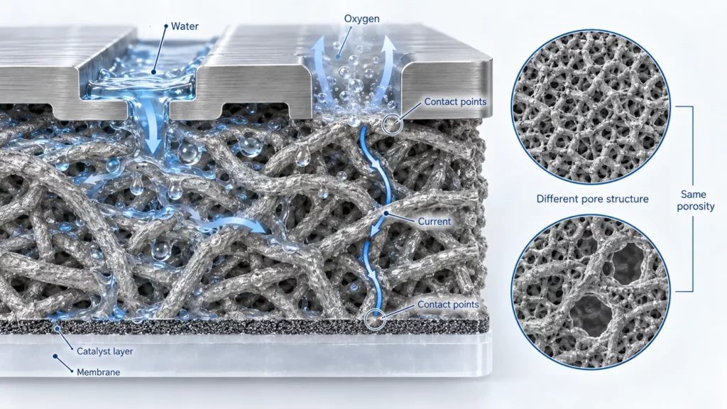
The anode-side PTL distributes water and assists oxygen removal. The cathode-side porous layer supports hydrogen transport and electrical contact. Both sides influence heat transfer, interface contact, and mechanical load transfer.
DOE-supported PTL development treats water flow, strength, and electrode contact as coupled targets. Porosity alone is insufficient.
Common structures and manufacturing variables
PTLs may use sintered powder, fiber or felt, mesh, or graded titanium structures. Control these variables:
- Thickness and local variation
- Porosity and pore-size distribution
- Roughness and contact morphology
- Flatness and edge condition
- Compression and permanent deformation
- Surface oxide, treatment, or coating
Equal bulk porosity can hide different pore distributions and contact behavior. Specify both the measurement and sampling method.
Surface engineering and inspection
Titanium passivation resists corrosion but may increase contact resistance. DOE electrolyzer test guidance notes that PTL coatings are often used to reduce contact resistance and increase durability.
| PTL parameter | Main function affected | Inspection focus |
|---|---|---|
| Thickness | Compression and interface position | Average and local variation |
| Porosity | Water and gas transport | Method and lot consistency |
| Pore structure | Local transport and contact | Distribution, not only average |
| Flatness | Contact-pressure uniformity | Full-area deviation |
| Surface condition | Contact resistance | Oxide, contamination, roughness |
| Coating | Corrosion and electrical stability | Coverage, adhesion, defects |
Catalyst-Coated Membrane Manufacturing
A catalyst-coated membrane, or CCM, carries catalyst layers on the membrane. It is not automatically a complete MEA, which may also include subgaskets, frames, or porous layers.
Catalyst ink preparation
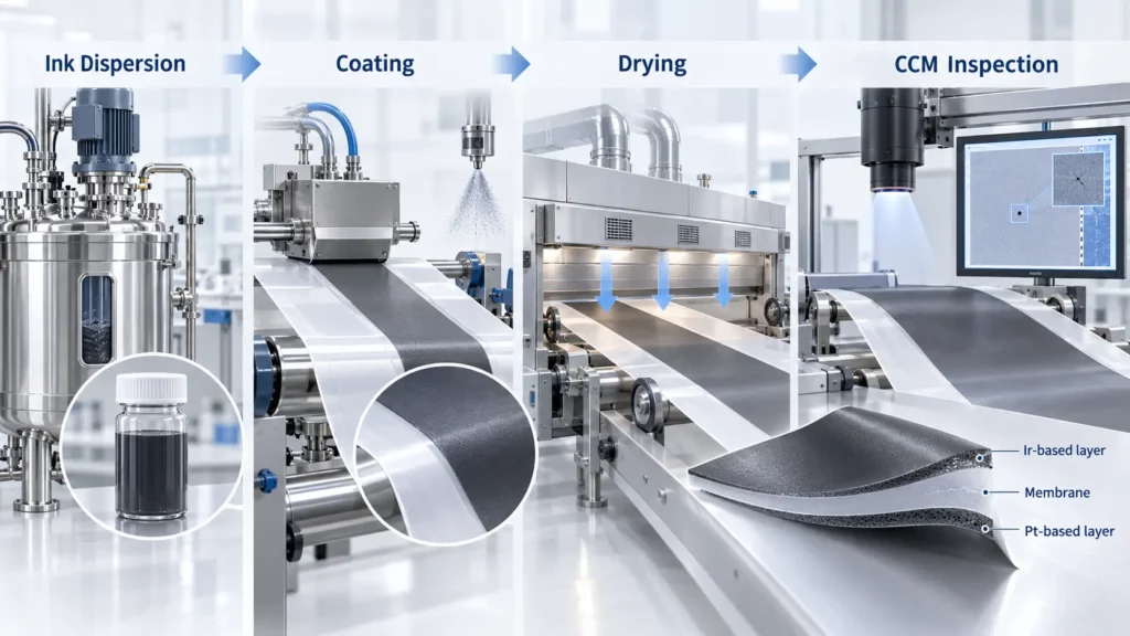
The ink combines catalyst, ionomer, and solvent. Control their ratio, solids content, viscosity, particle distribution, mixing order, dispersion energy, and usable time. Poor dispersion causes agglomerates, nozzle blockage, or uneven coating.
Experimental work on IrO₂ catalyst inks shows that dispersion method changes particle distribution, stability, and rheology. Ink preparation is therefore a coating CTQ.
Catalyst-layer formation
Routes include direct coating, spray, transfer or decal, screen printing, and slot-die coating. Selection depends on rheology, membrane handling, loading, area, drying, and volume. NREL’s updated PEM electrolyzer manufacturing analysis models both spray and slot-die routes.
Drying and membrane handling
Drying must remove solvent without creating cracks, large gradients, contamination, or membrane distortion. Control temperature, airflow, dwell time or line speed, and web tension.
Hot pressing may be used for selected catalyst-layer transfer, CCM, or MEA assembly routes, but it is not universal. The validated method depends on membrane type, catalyst-layer architecture, subgasket design, and the supplier’s assembly process.
Catalyst loading and CCM inspection
Uneven loading drives local current-density variation. Inspect total and spatial loading, dimensions, edges, cracks, pinholes, and membrane damage. Combine loading measurement with optical inspection where suitable.
Frames, Gaskets, and Sealing Components
Frames and gaskets control fluid separation, ports, component position, and compression boundaries. Select materials for water chemistry, temperature, gas exposure, differential pressure, and creep.
Inspect thickness, geometry, ports, sealing-land overlap, and damage. Common risks are:
- Misalignment: Blocks a port or reduces sealing overlap.
- Insufficient compression: Leaves an external or internal leakage path.
- Excessive compression: Damages the seal or changes adjacent PTL thickness.
- Particle or edge damage: Creates a local path across the sealing land.
Develop seal, plate, and compression specifications together.
PEM Electrolyzer Cell Assembly
Cell assembly controls interfaces. A typical repeat unit is:
Plate → Anode PTL → CCM/MEA → Cathode porous layer → Plate
The sequence varies by design. Align ports, active area, catalyst layers, porous layers, frames, gaskets, and plate datums.
Cleanliness is a CTQ. Particles can distort contact or damage the membrane. Fingerprints, residue, and metal debris can contaminate electrical or sealing interfaces.
Inspect PTL–CCM, PTL–plate, and gasket–plate contact during development. Stack behavior depends on these interfaces.
Stack Assembly and Compression Control
Stack assembly repeats the cell unit between current collectors, end plates, and compression hardware. Load must maintain sealing and contact without damaging the membrane or PTLs.
| Compression condition | Likely result |
|---|---|
| Too low | High contact resistance, weak sealing, unstable interfaces |
| Too high | PTL deformation, seal over-compression, membrane-interface stress |
| Uneven | Local resistance, local leakage, non-uniform cell behavior |
Bolt torque is indirect. Friction, threads, end-plate stiffness, component thickness, and tightening sequence change actual contact pressure. Torque alone does not prove full-area uniformity.
Published compression values are test-specific and should not be copied directly into a production drawing. The validated range depends on PTL architecture, gasket thickness, active area, plate stiffness, temperature, pressure, and compression history.
Define tightening order, passes, calibrated tooling, and final stack height. During development, correlate tightening conditions with load cells, bolt elongation, calibrated compression fixtures, pressure-sensitive films where chemically and geometrically suitable, or another validated method.
PEM Electrolyzer Quality Control and End-of-Line Testing
Use three quality gates: incoming, in-process, and assembled-stack testing. This locates defects nearer their source.
| Test or inspection | What it verifies | Typical control stage |
|---|---|---|
| Dimensional inspection | Plate, PTL, seal, alignment | Incoming / in-process |
| Surface inspection | Coating, residue, scratches | In-process |
| Contact resistance | Interface or coating behavior | Component / sample |
| Leak test | External and internal sealing | Cell / stack EOL |
| Pressure integrity | Structure at defined conditions | Qualification / specified EOL |
| Insulation test | Electrical isolation from structure | Stack end-of-line |
| Flow test | Port and channel continuity | Stack EOL |
| Polarization curve | Voltage-current performance | Functional validation |
| EIS | Ohmic and interface loss diagnosis | Development / selected checks |
| Gas analysis | Crossover and stack gas composition | Functional validation |
The DOE electrolyzer testing capability includes polarization, AC impedance, voltammetry, stress tests, and gas analysis. Development should identify the smaller test set needed for production.
Stack test data may support later system-level safety and conformity work, but this guide does not cover complete electrolyzer certification. For example, ISO 22734-1:2025 addresses safety requirements for complete hydrogen generators that use water electrolysis. Do not treat a passing stack test as system certification.
Set acceptance criteria from the approved design. Do not copy limits without confirming pressure, area, materials, and duty cycle.
Common PEM Electrolyzer Manufacturing Defects
| Defect | Likely manufacturing cause | Possible effect |
|---|---|---|
| Uneven channels | Etching, forming, or tooling variation | Flow maldistribution |
| Plate warpage | Forming force, residual stress, or thermal exposure | Poor sealing or contact |
| Coating pinholes | Surface contamination or deposition variation | Local corrosion risk |
| PTL thickness variation | Porous-material process variation | Uneven compression and contact |
| CCM loading variation | Ink or coating instability | Local current-density variation |
| Catalyst-layer cracks | Drying or formulation problem | Unstable local performance |
| Port misalignment | Datum, cutting, or assembly error | Flow restriction or leakage |
| Uneven stack compression | Hardware stiffness or tightening variation | Resistance and leakage variation |
| Seal damage | Handling or excessive compression | Internal or external leakage |
| Particle contamination | Weak cleaning or assembly control | Membrane, sealing, or contact defect |
Confirm the failure with measurements before changing the process.
Critical-to-Quality Controls Across the Manufacturing Chain
CTQs connect each process to a failure mode and inspection method.
| Component | Process | Primary CTQ | Main failure | Inspection approach |
|---|---|---|---|---|
| Plate | Etching or forming | Channels and flatness | Maldistribution or leakage | Optical, profile, or CMM |
| Coating | Surface treatment | Coverage and resistance | Corrosion or electrical loss | Surface and electrical tests |
| PTL | Porous manufacturing | Thickness, porosity, surface | Transport or contact loss | Thickness, porosity, surface |
| CCM | Coating and drying | Loading and uniformity | Local performance loss | Loading and optical checks |
| Seal | Cutting or molding | Geometry and thickness | Leakage | Dimensional and visual inspection |
| Stack | Assembly | Alignment and compression | Resistance or leakage | Height, load, electrical, leak |
See related bipolar plate specifications and testing. Adapt all limits to the PEMWE environment.
Prototype Manufacturing vs Mass Production
Prototype manufacturing should maximize learning. Flexible tooling, rapid drawing changes, dimensional reports, and small-batch inspection connect geometry with cell results.
Mass production must hold a proven process window at target takt time. It requires capability monitoring, efficient inspection, traceability, yield tracking, and reaction plans.
| Prototype priority | Mass-production priority |
|---|---|
| Fast CAD iteration | Stable released design |
| Flexible tooling | Repeatable high-throughput process |
| High inspection per part | Automated or sampled inspection |
| Individual failure learning | Statistical control and yield management |
| Manual or semi-automatic work | Error-proofed, traceable assembly |
A laboratory process does not scale automatically. Verify cycle time, capacity, process window, measurement repeatability, supply continuity, scrap drivers, and yield at target volume.
Where Stack Manufacturing Ends
This guide stops at the qualified stack and its defined interfaces. Power electronics, deionized-water circulation, gas-liquid separation, hydrogen drying, cooling, sensors, controls, and complete-system certification belong to balance-of-plant integration.
The stack release package should define electrical connections, pressure boundaries, fluid ports, thermal limits, sensor interfaces, and the validated operating envelope. These outputs become inputs to a separate system-integration process.
PEM Electrolyzer Manufacturing Checklist
Before releasing a stack, verify:
- Material identity, certificates, and lot traceability are complete.
- Plate channels, ports, sealing lands, and flatness meet the drawing.
- Plate surfaces and coatings meet inspection criteria.
- PTL thickness, porosity, surface, and compression meet specification.
- CCM loading, dimensions, edges, and membrane condition pass.
- Gaskets, ports, active areas, and porous layers are aligned.
- Assembly cleanliness records are complete.
- Tightening sequence, stack height, and compression are verified.
- Leak, pressure, insulation, and flow checks pass.
- Functional results meet approved acceptance criteria.
- Crossover and stack gas-analysis results meet the approved test plan.
- Nonconforming parts and rework remain traceable.
Frequently Asked Questions
What are the main manufacturing steps for a PEM electrolyzer?
The sequence is requirements, incoming inspection, plate, PTL and CCM production, seals, cell assembly, stack compression, end-of-line testing, and production release.
What is a PTL in a PEM electrolyzer?
The anode-side PTL distributes water and assists oxygen removal. The cathode-side porous layer supports hydrogen transport and electrical contact. Control thickness, pore structure, surface condition, and compression together.
Why is titanium commonly used for PEM electrolyzer PTLs?
Titanium resists the anode environment. Its passive surface can increase contact resistance, so treatment or coating may be required.
How is a catalyst-coated membrane manufactured?
Catalyst and ionomer are dispersed in solvent. Layers are coated or transferred onto the membrane, dried, and checked for loading, uniformity, cracks, edges, and membrane damage.
How are PEM electrolyzer bipolar plates manufactured?
Metal plates can be etched, stamped, hydroformed, or machined. Select by thickness, channel geometry, tolerance, design maturity, tooling, and volume. Then clean, coat, and inspect as required.
What tests are performed after PEM electrolyzer stack assembly?
A stack plan may include leak, pressure, insulation, flow, and functional tests. Polarization curves verify performance. EIS and gas analysis support development, diagnosis, qualification, or selected production checks.
Conclusion
PEM electrolyzer stack manufacturing is both component production and interface control. Plate geometry, PTL structure, CCM uniformity, seals, alignment, cleanliness, and compression must remain compatible.
Use one repeatable logic: define, manufacture, inspect, assemble, compress, test, and scale. For thin flow-field plates, review geometry, material, coating, inspection, and volume before prototyping. This reduces redesign before production release.