
In metal bipolar plate fabrication for proton exchange membrane, or PEM, fuel cells, the next step depends on what has been tested. A formed channel shows that a tool can make a feature. A working short stack shows that assembled plates can operate under the conditions of that test. This guide compares three published examples: electromagnetically driven forming, micro-roll forming, and laser powder bed fusion. It identifies the evidence each example provides and what a project still needs before pilot production. For a sourcing decision among established routes, start with the bipolar plate manufacturing process comparison.
Key takeaways
- Check what was tested: a channel sample, a tool, a complete plate, or an assembled stack.
- Read each result alongside its alloy, thickness, geometry, and test conditions.
- Before committing to pilot production, verify the finished plate, its assembly interfaces, and repeatability across batches.
What Does Manufacturing Readiness Mean for a Bipolar Plate?
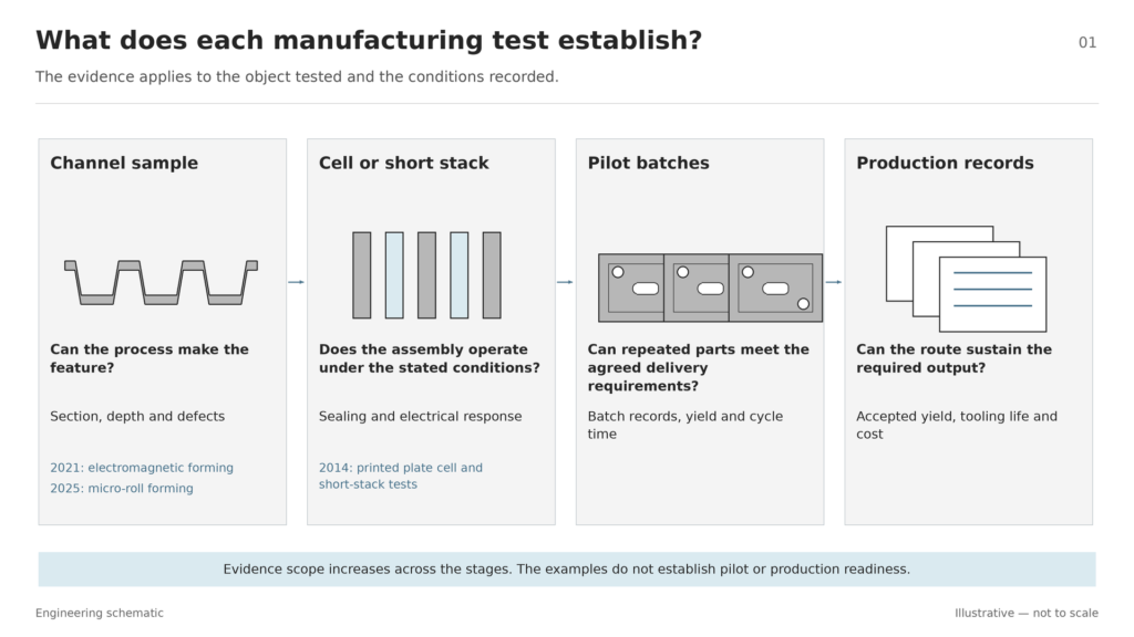
Start with the part your project needs to receive. If the drawing calls for a joined plate with a specified surface finish, a channel sample answers only the forming question. To judge readiness for that delivery condition, look for evidence from increasingly representative production conditions, including the planned materials, equipment, and tooling.
| Evidence stage | Question it answers | Records to check |
|---|---|---|
| Formed or printed sample | Can this material take the intended shape? | Channel sections, remaining thickness, and defects |
| Cell or short-stack test | Does the assembly work under the stated conditions? | Sealing, pressure drop, voltage under load, impedance, and test duration |
| Pilot production | Can the planned process repeatedly make the intended part? | Batch measurements, joining, finish, leakage, cycle time, and yield |
| Production evidence | Can the process sustain the required output? | Accepted-part yield, equipment and tooling life, inspection, and cost |
Use these stages to compare what the published examples establish. The labels apply to the evidence in each example, rather than assigning a readiness score to an entire technology.
Three Emerging Routes and the Evidence Behind Them
Electromagnetically Driven Forming for Thin-Sheet Microchannels
The earlier version of this article used the term high-velocity electromagnetic forming, or HVEF. In the 2021 electromagnetically driven forming trial, a magnetic pulse moved a tool. A liquid transferred the force from the tool to 0.1 mm 1.4404 stainless steel foil, pressing it into a die with a serpentine pattern representative of a bipolar plate flow field.
The measured channel sections in Figure 3 show that the tool formed the selected pattern. The depth varied across the sample because the spiral coil loaded the membrane unevenly. In the illustrated comparison, raising the capacitor charging energy from 12.5 to 15 kJ increased the forming depth by about 10%. That result applies to the setup and settings tested.
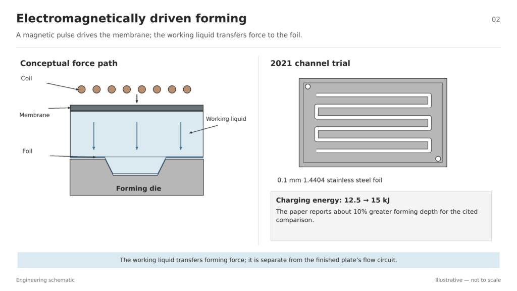
Evidence stage: channel proof of concept. For a full plate trial, map channel depth and remaining metal thickness across the flow field. Check the same locations on consecutive parts before moving to assembly tests.
Micro-Roll Forming for Repeated Channel Profiles
In micro-roll forming, successive roll stations bend the sheet in steps. The 2025 trials used 0.1 mm Grade 2 commercially pure titanium cut into 50 × 300 mm strips. The operators fed the strips by hand and turned the rolls with a crank. The first two stations formed the profile, and the third sized it to the final shape.
The formed sections and thickness measurements show how the profile changed through the stations. The trials assessed springback, the change in shape after forming pressure is released, and local thinning. After final sizing, thinning reached 32.5% at one radius of the center channel in the tested profile.
The forming trials covered profiles with up to three channels. A separate nine-channel profile was cut and measured on a top roll. That measurement establishes what was made on the tool; the foil results apply to the narrower test profiles.
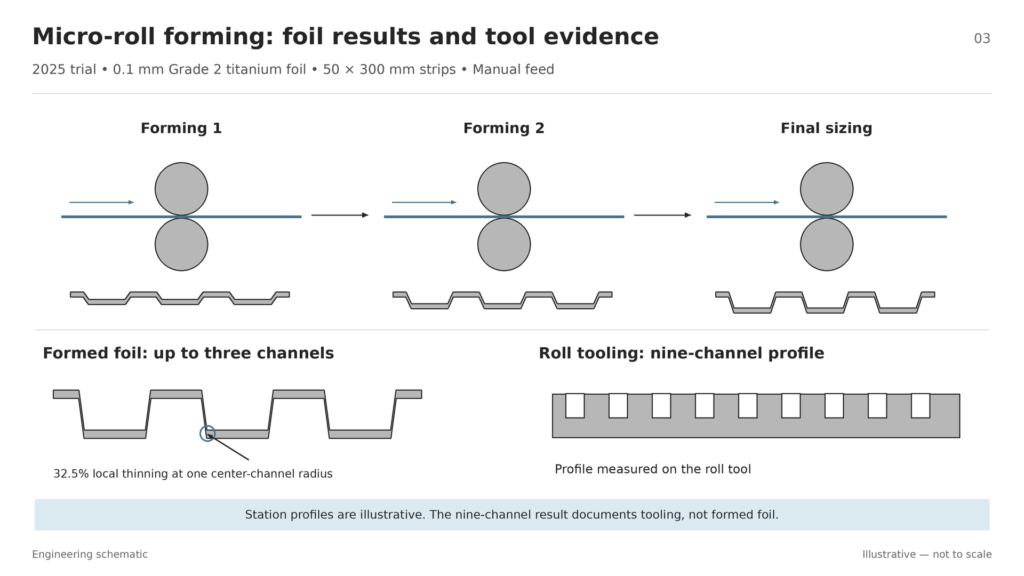
Evidence stage: trial equipment and formed strips. A pilot proposal needs full-width samples, checks on ports and sealing areas, and measurements from consecutive parts under the proposed feed conditions.
Laser Powder Bed Fusion for Metal Plate Prototypes
Laser powder bed fusion, or LPBF, builds a part by melting selected areas of metal powder, layer by layer. The 2014 selective laser melting trial used 316L stainless steel, a 5 mm plate design, and a serpentine channel with a 1 × 1 mm cross-section. The printed plates were wire-brushed to remove loose powder. High spots were then sanded before cleaning and assembly.
The single-cell comparison and short-stack test used humidified hydrogen at 35 standard cubic centimeters per minute and fan-fed air. The tests measured voltage as current changed and used impedance to examine the electrical response. Single cells fitted with printed or milled plates showed comparable voltage curves and resistive response in this setup. The printed plates also ran in a two-cell short stack.
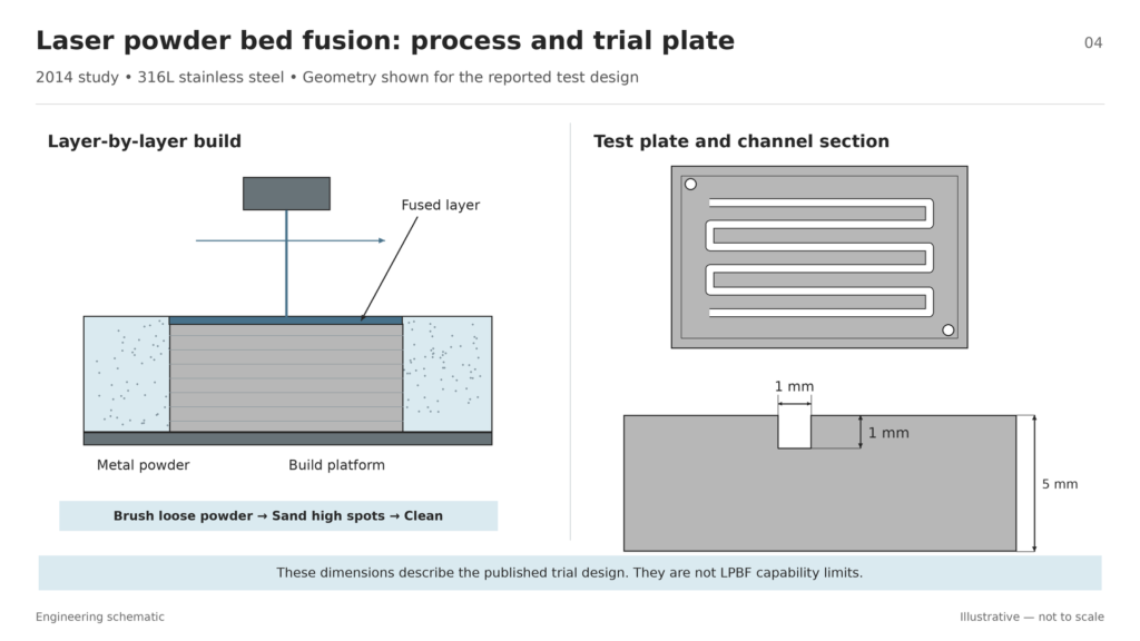
Evidence stage: single-cell comparison and short-stack operation. For a design intended to replace a thin sheet part, request samples at the target thickness. Verify sealing surfaces, the finish after post-processing, and performance over the required operating duration.
Compare the Evidence Across the Three Routes
The year identifies the publication. The test object tells you which project question the evidence can answer.
| Route | Year | What was tested | Evidence still needed for the next step |
|---|---|---|---|
| Electromagnetically driven forming | 2021 | Serpentine channels in stainless steel foil; measured sections | Full-plate uniformity, repeatability, and assembly tests |
| Micro-roll forming | 2025 | Titanium strips and roll tooling; profile and thinning checks | Full-width parts and records from repeated runs |
| Laser powder bed fusion | 2014 | 316L plates in single cells and a two-cell stack; voltage and impedance | Target thickness, durability, yield, and throughput |
Use the first two examples to frame questions about forming and dimensional control. Use the printed example to frame questions about assembly and short-term operation. A direct cost or performance comparison needs a common drawing, delivery condition, and test plan.
What Must Be Verified Before Pilot Production?
Agree on three decisions before setting the pilot scope:
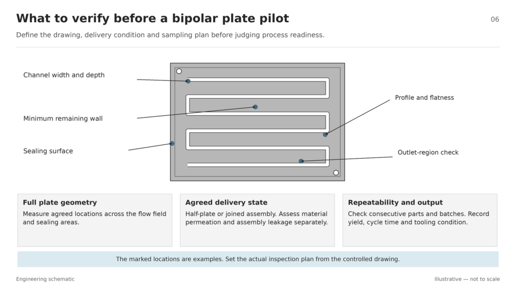
- Does the sample represent the target plate? Check the complete flow field, channel width and depth, minimum remaining wall, flatness, and sealing areas against the drawing.
- What condition must the supplier deliver? Specify whether the part is a half-plate or a joined assembly. Define the bonding or welding method, surface treatment, and tests for the finished part. Use corrosion, electrical contact, and hydrogen permeation as separate evaluation categories where relevant. Verify assembly leakage separately.
- Can the process sustain the required output? Request yield, rate, and tooling evidence for the proposed line. Compare the cost per accepted plate, including post-processing and inspection, at the same delivery condition.
For alloy and coating decisions, see metal bipolar plate materials and surface requirements.
TMNetch Case: From Separate Plates to Closed Channels
In a TMNetch bipolar plate welding project, laser welds at bridges on the anode and cathode plates closed the flow channels. The case illustrates why the delivery drawing should identify the final assembly. For a similar job, specify where to check flatness after joining and define how the completed assembly will be tested for leaks.
Where Chemical Etching Fits in Prototype Development
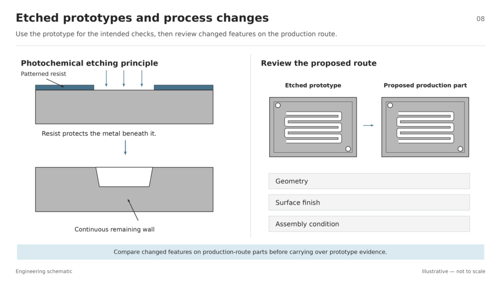
For a prototype with recessed channels in thin sheet, consider photochemical etching. A patterned resist protects areas that must remain while the etchant removes exposed metal. Use the etched flow field design guide to specify the channel section, remaining wall, and inspection points before ordering parts.
If you intend to switch processes after testing an etched plate, record any change in geometry, finish, or assembly condition. Use the established manufacturing route comparison to decide what should be checked again on parts made by the proposed production process.
Review Your Metal Bipolar Plate Prototype
Planning custom etched metal bipolar plates? Share your material, sheet thickness, channel geometry, and delivery requirements with TMNetch for a chemical etching feasibility review.
Frequently Asked Questions
Can Electromagnetic Forming Make Channels for Metal Bipolar Plates?
Yes. A thin-foil trial formed serpentine channels by using a liquid to transfer force from a pulsed tool to the foil. For a new plate, verify depth uniformity and remaining thickness over the full pattern.
Does a Short-Stack Test Establish Production Readiness?
A short-stack test shows how the assembled plates operate under the recorded conditions. To judge production readiness, also check whether the process can deliver repeatable parts at the required rate, yield, and finished condition.
Conclusion
The electromagnetically driven forming trial and the micro-roll forming trial demonstrated channel formation in thin foil. The laser powder bed fusion trial showed that printed 316L plates could operate in a two-cell short stack under the reported test conditions.
Before moving to a pilot run, check that the proposed process can produce your full plate geometry and that the finished assembly meets your sealing and surface requirements. Use the pilot to measure yield and cycle time across batches.