
Chemical etching uses a light-sensitive pattern and chemical removal to make thin-metal components for electronic and telecom equipment. Also called photochemical machining, or PCM, it produces parts such as shields, contacts, lead frames, grilles and perforated screens. To assess a part, review its material, critical features, final delivery condition and inspection requirements together.
This guide connects those component categories to practical drawing and acceptance checks. Engineers and buyers can use TMNetch’s electronic component etching services page to discuss a specific drawing and supply scope.
Key takeaway: Define what the metal part must do, specify its finished condition, and agree how the supplied component and assembled product will be verified.
What Does Chemical Etching Make for Electronics and Telecom?
Chemical etching for electronics covers several thin-sheet component families. Start with the function and supplied item, then identify the features that need review.
| Function | Representative components | Review focus |
|---|---|---|
| Shielding and grounding | Shield blanks, covers and grounding contacts | Openings, seams, contact areas and assembled shape |
| Connection and packaging | Lead frames, contacts, shims and spacers | Material condition, feature positions and final finish |
| Audio and protection | Speaker grilles, perforated screens and filters | Opening pattern, active area, support and appearance |
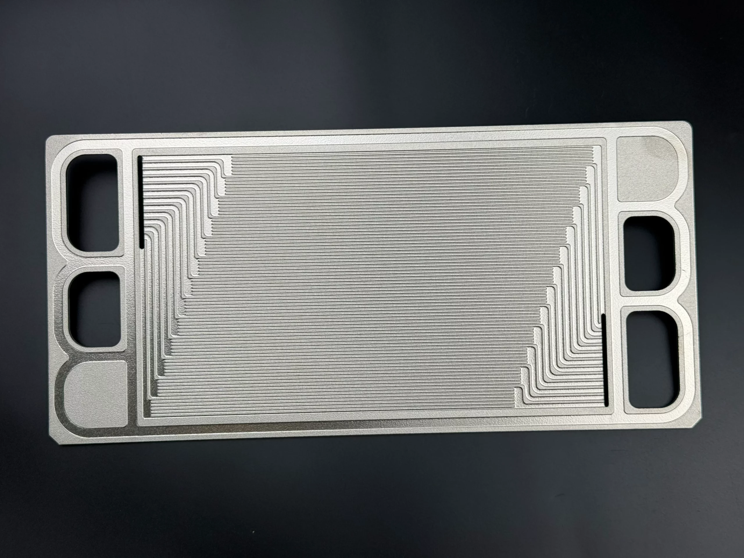
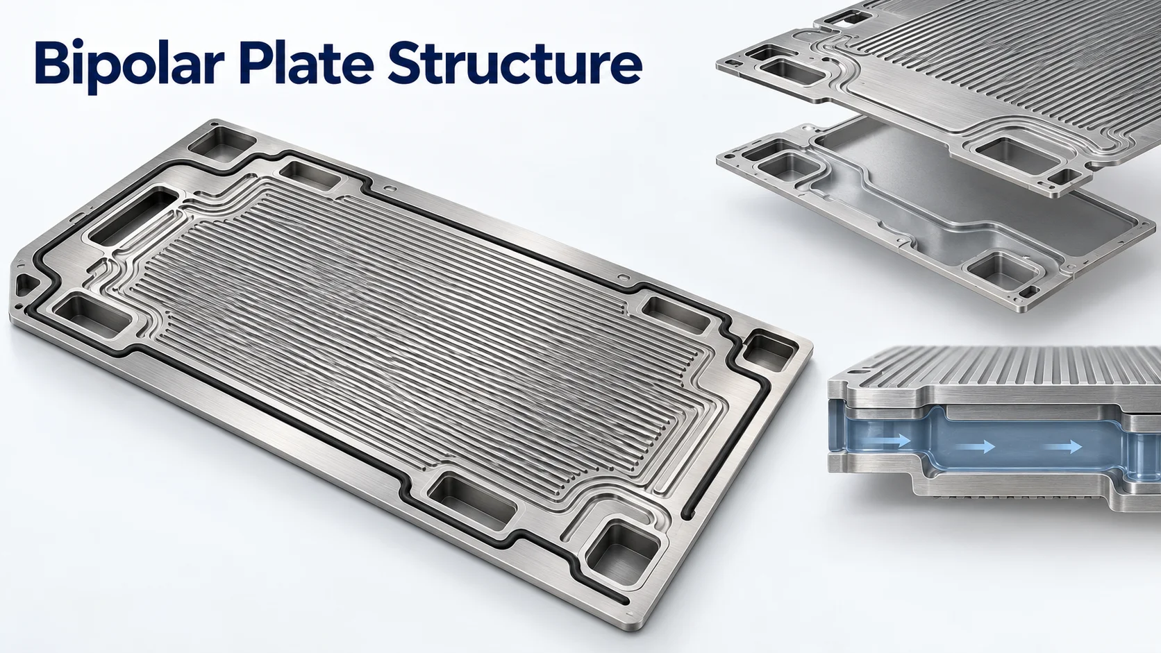
| Thermal management | Patterned plates or internal metal features | Feature depth, remaining thickness and assembly responsibilities |
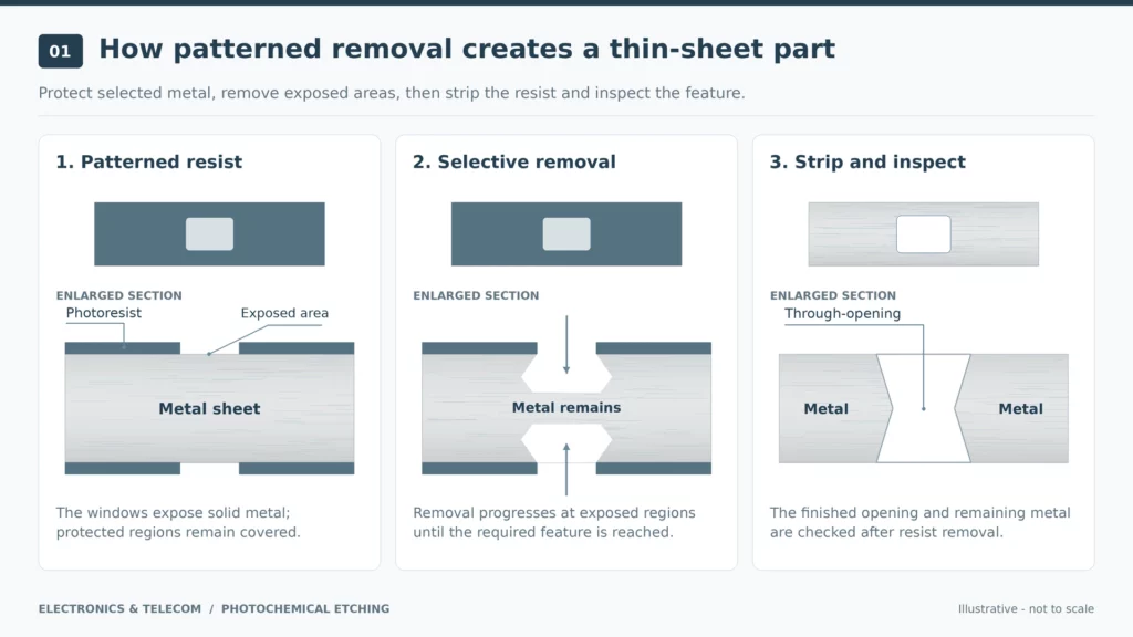
The PCM manufacturing process starts with artwork and phototool preparation. Clean metal receives a light-sensitive protective coating called photoresist, which is exposed and developed into a pattern. Chemical etching removes exposed metal, followed by resist stripping, cleaning and inspection.
Define whether the order covers a flat blank, a formed part or a finished component ready for the next assembly step.
EMI/RFI Shielding and Grounding Components
Chemically etched telecom components include shielding parts for mobile devices and telecom equipment. Electromagnetic interference, or EMI, is unwanted electromagnetic disturbance; radio-frequency interference, or RFI, concerns disturbance at radio frequencies.
Define the Shielding Task and Assembly Boundaries
Start with the interference problem, relevant frequency range and regions that need isolation. For a wireless module or network device, show how the shield relates to nearby components, the enclosure and the grounding arrangement.
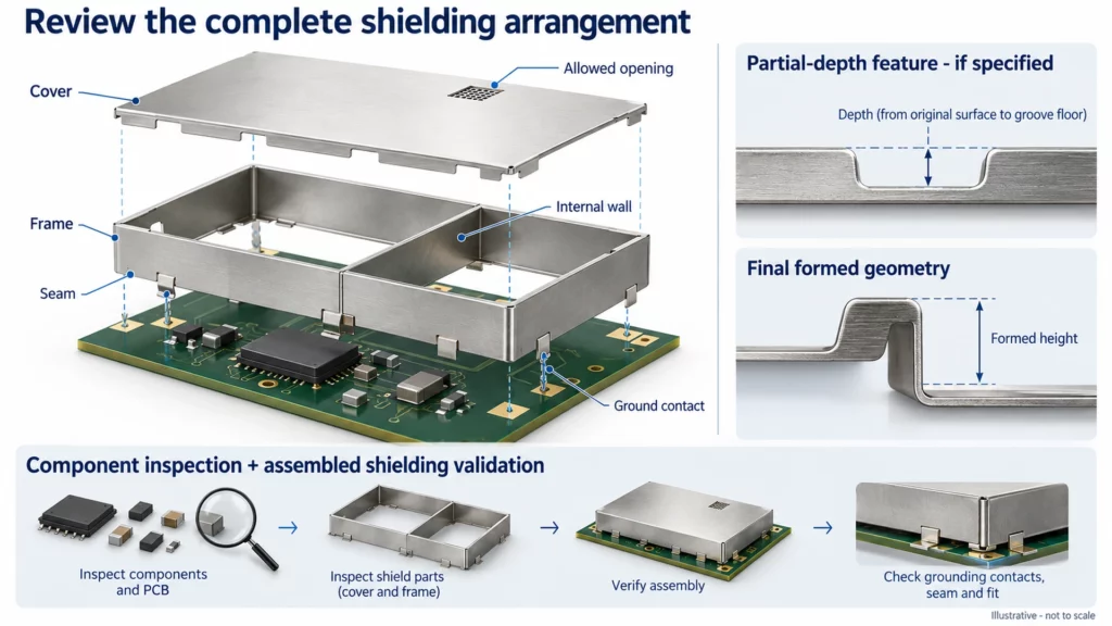
Openings and gaps in board-level shields can affect shielding effectiveness, including leakage between internal cavities. Review the complete arrangement:
- Which areas require continuous metal coverage, and where are openings allowed?
- How do the cover, frame, corners and internal walls meet?
- Where are the grounding contacts, and what surfaces must remain exposed?
- Must the cover support removal, servicing or repeated assembly?
Assign responsibility for testing the shield in the intended equipment configuration. A dimensionally accepted blank provides only part of the evidence needed for that assessment.
Specify the Etched Part and Its Final Condition
For EMI/RFI shielding components, identify the flat profile, any partial-depth features, bend locations and required finish. State whether the supplier delivers the blank, formed frame, cover or another defined item.
Mark assembled height and contact locations as inspection features where required. If a drawing includes a partial-depth bend feature, specify its location and depth requirements separately from the final formed geometry. Agree how both will be checked.
Lead Frames, Contacts and Connection Parts
Etched lead frames and contacts need defined electrical interfaces and assembly geometry. Specify the features that connect, locate or support the part before reviewing production options.
Lead Frames and Electrical Contact Features
A lead frame connects semiconductor terminals to external circuitry. Both stamping and chemical etching are used to manufacture lead frames, so assess the route against the actual drawing and order requirements.
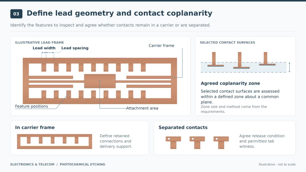
For custom etched lead frames, identify critical lead widths, spacing, positions and attachment areas. Define coplanarity where needed: the requirement for selected contact surfaces to lie within an agreed zone about a common plane.
Specify whether parts remain attached to a carrier frame or arrive separated. Mark permitted retaining tabs and the acceptable condition after removal. For plated contacts, identify the coating, covered areas and features to inspect after finishing.
Shims and Spacers for Electronic Assemblies
For an electronic assembly shim, state the required seating thickness, locating features and flatness. Identify the surfaces that contact adjacent parts and any edge restrictions.
If a spacer sits beneath a board or housing feature, show its assembly position on the drawing. Agree which dimensions control the gap and whether inspection uses the free part or a specified support arrangement.
Speaker Grilles, Etched Filters and Protective Screens
Perforated parts need both an opening pattern and a clear definition of the area that performs the function. Review the surrounding border, mounting method and final surface alongside the holes.
Speaker Grilles for Mobile and Audio Products
Etched grilles are used in mobile-phone audio openings and smart or Bluetooth speaker panels. These are industry application examples.
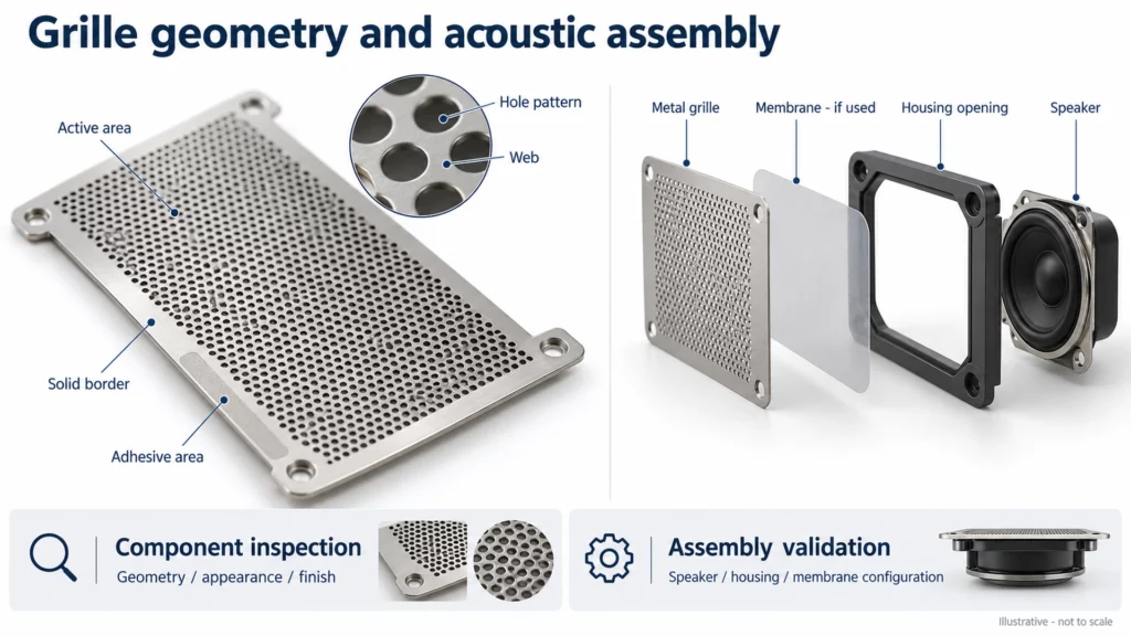
For custom speaker grilles, define hole shape, spacing and the metal remaining between openings, called the web. Mark the perforated area, solid mounting border and any areas reserved for adhesive or forming.
Specify the visible face, coating, color and cosmetic acceptance method. If appearance matters, agree a reference sample and viewing conditions before approving production.
Keep dimensional inspection and acoustic validation as separate acceptance tasks. Identify who tests the grille with the speaker, housing and any additional membrane, and record the configuration used for sample approval.
Etched Filters and Screens: Define the Opening Requirements
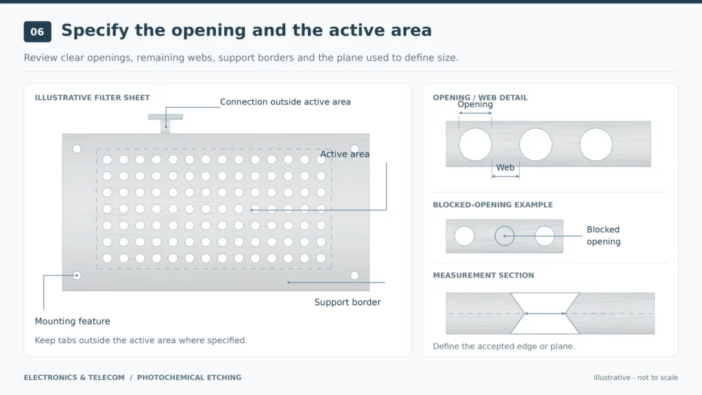
For a chemical etching filter project, state whether the sheet serves particle screening, airflow protection, physical guarding or another task. Give the clear opening dimensions and active area, then define the supporting border and mounting features.
For etched metal filters and screens, specify acceptable blocked openings, edge condition, cleanliness and packaging. If a retaining tab would obstruct the active area, mark that area as excluded from tab placement.
Where the order requires filtration, dust protection or airflow performance, agree the test method and assembled condition. Treat a hole-size report and a functional test report as distinct deliverables, with the required results identified for each.
Etched Metal Parts for Thermal Management
For thermal-management work, define the particular plate or internal feature being reviewed. Identify local depth, remaining wall thickness, flatness and surfaces reserved for subsequent joining.
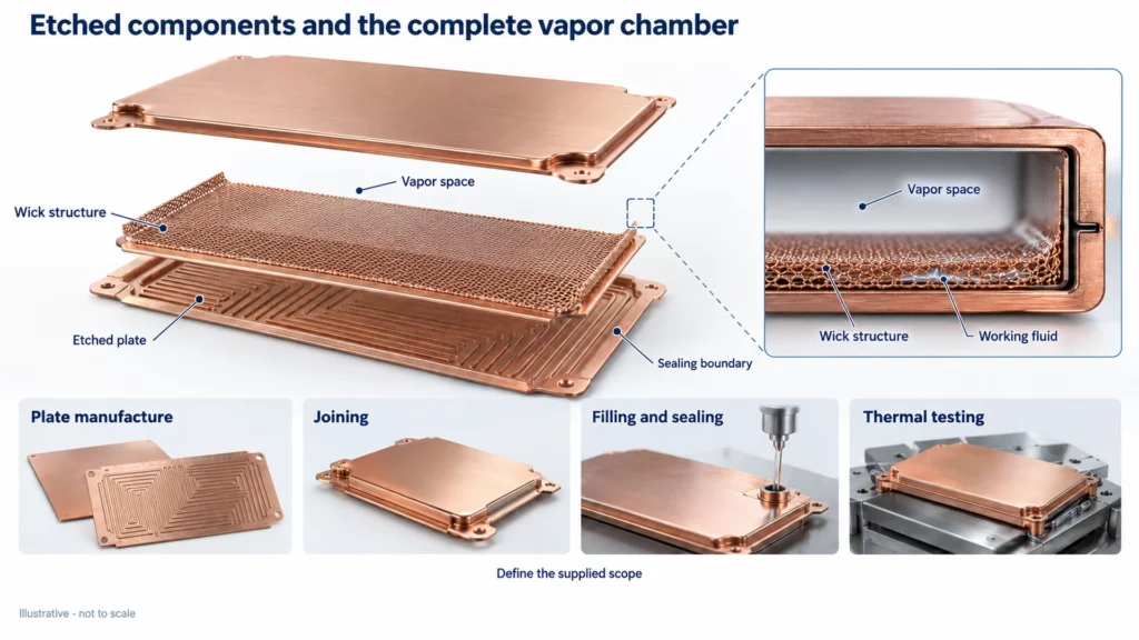
A complete vapor chamber contains a sealed shell, working fluid and wick structure. An etched plate therefore represents a defined part of a larger manufacturing and validation scope.
When discussing vapor chamber components, confirm whether the inquiry covers patterned plates, internal structures or an assembled unit. Agree who performs joining, filling, sealing and thermal testing where applicable. Request capability evidence for that specific scope before accepting thickness, heat-transfer or operating-performance claims.
Material Grade, Condition and Surface Finish
Define material by its exact specification, supplied condition and required surface. Use those inputs to review the proposed part and subsequent operations.
Phosphor Bronze and Brass: Specify the Exact Alloy
For phosphor bronze photochemical etching, identify the alloy designation, material condition, thickness and finish. Apply the same input discipline to brass photochemical etching.
For a contact or spring feature, submit the required working position, deflection and acceptance criteria with the material specification. Review the grade-specific material data for the intended function. A material family name alone leaves too much undefined for approval.
For example, specify the selected grade and temper, meaning its supplied material condition, on the controlled drawing. Require engineering approval before a supplier changes either input.
Match the Material and Finish to the Delivery State
For stainless steel, copper, nickel alloys, aluminum or another specified metal, confirm the exact grade and available stock condition. Request a separate feasibility review for specialist alloys rather than extending approval from a different material.
Use this input chain: grade/specification → condition/thickness → surface finish → final delivery state.
Identify protected contact faces, cosmetic surfaces and areas excluded from coating. State which dimensions apply after etching, forming, plating or painting. Include any subsequent treatment in the agreed process scope and acceptance plan.
Drawing Review and Dimensional Acceptance
Review the drawing against the features that control fit, assembly and function. Turn a general request for precision into dimensions and checks that both parties can interpret consistently.
Identify the Features That Control Fit and Assembly
Provide the part number, revision, controlled drawing and applicable computer-aided design, or CAD, files. State which document controls if the files differ.
Mark reference features, critical holes, webs, mounting positions and retaining-tab locations. For partial-depth features, specify depth and remaining thickness where required. Agree which face or measurement plane defines a critical opening.
Inspect in the Agreed Final Condition
Select inspection equipment around the design information and measurement requirements. For flexible parts, agree support conditions and reference locations before comparing results.
| Check | Define in the acceptance plan |
|---|---|
| Geometry | Critical dimensions, references, thickness, depth and measurement locations |
| Edges and surfaces | Tab-removal condition, protected areas, coating and cosmetic requirements |
| Measurement state | After etching, forming or the specified final treatment |
| Function and records | Test responsibility, assembly configuration, material documents and inspection reports |
Apply the relevant checks to the project and retain the agreed definitions with the drawing revision.
Illustrative drawing-review example: A formed grounding contact needs a plated contact face and a mounting slot. The drawing identifies the alloy, temper, contact position and final formed height. The review places retaining tabs away from the contact face and assigns dimensional checks after forming and plating.
The equipment team owns the assembled electrical test. This example shows how to define responsibilities; it does not describe a verified TMNetch production delivery.
What to Send for an Electronic Component Review
Prepare a package that lets the supplier assess the complete deliverable:
- Controlled drawing revision and applicable CAD files.
- Material grade, condition and thickness requirements.
- Critical features, sample quantity and expected production quantity.
- Forming, finishing, separation and packaging scope.
- Required inspection, functional testing and supporting records.
Use that package for an electronic component etching project review. Ask the proposed supplier to identify unresolved features, subsequent operations and any exceptions before quotation approval. Compare offers against the same finished-part scope, documentation and acceptance requirements. Confirm timing after those inputs and responsibilities are agreed.
Frequently Asked Questions
What electronic and telecom components can be chemically etched?
Representative parts include shields, contacts, lead frames, shims, grilles and perforated screens. Confirm feasibility from the actual material, geometry, finish and supplied condition.
Can metal encoder disks be chemically etched?
Yes, chemical etching is an established metal encoder disk manufacturing route. For custom encoder disks, submit the track pattern, mounting references and inspection needs; define encoder-system validation separately.
Are etched parts ready for assembly without further processing?
The order defines that condition. Specify whether delivery includes forming, finishing, tab removal, cleaning and packaging, then identify any work remaining before assembly.
Is chemical etching always cheaper than stamping?
There is no single cost ranking for every electronic component. Compare quotations for equivalent deliverables, including material, geometry, quantity, tooling, subsequent processing and inspection scope.
Conclusion: Review the Component, Material and Final Condition
Start with the component’s function, then define its material, geometry and delivered condition. Agree dimensional acceptance, functional-test responsibilities and required records before approving production.
Explore TMNetch’s chemical etching services for broader manufacturing context. To request an electronic component review, send your controlled drawing, material specification, thickness, quantity, final finish and inspection requirements. Include subsequent operations so the review and quotation address the complete supplied item.