
Quick Answer
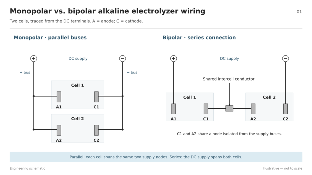
In a monopolar alkaline electrolyzer, each electrode has one polarity, and the anodes and cathodes connect to separate common busbars, putting the cells in parallel within the group. In a bipolar stack, a shared conductor connects one cell’s cathode to the next cell’s anode, putting the cells in series. To identify either layout on a drawing, trace the metal path and check which electrode roles meet at each node.
This guide focuses on conventional alkaline water electrolyzers. The PEM fuel-cell section shows how the term bipolar plate applies to a different device.
What Do Monopolar and Bipolar Mean?
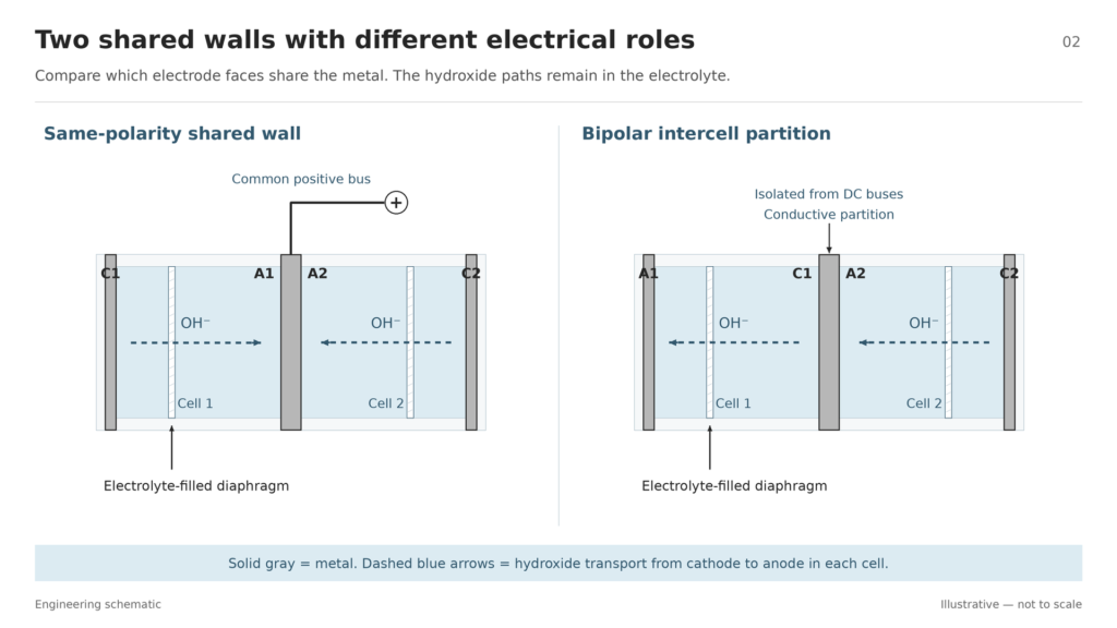
Monopolar describes the electrode arrangement and its electrical connection. A monopolar electrode assembly can have a conductive wall with an electrode on each face. In a shared-wall design, both faces can serve anodes or both can serve cathodes. The two electrodes share one supply node.
Bipolar describes an intercell connection. In a bipolar alkaline stack, one conductor joins the cathode side of one cell and the anode side of its neighbor. The metal forms a shared electrical node. The labels anode and cathode describe each side’s role in its own cell.
Terminology Quick Reference
| Term | Meaning | Common source of confusion |
|---|---|---|
| Monopolar electrode | An electrode with one polarity in the assembly. | A shared wall can serve two electrodes of the same polarity. |
| Monopolar configuration | A group of cells wired in parallel through separate anode and cathode buses. | The group can still contain conductive walls or plates. |
| Bipolar plate | A conductive plate that links opposite electrode sides in adjacent cells. | The electrical connection determines the name. |
| Flow-field plate | A plate identified by its fluid-distribution channels. | Its electrical role depends on how the plate is installed and connected. |
| Busbar | A common conductor that distributes or collects current. In the parallel layout, each bus connects electrodes of the same polarity. | The bus serves a common supply node. A bipolar plate serves an intercell node. |
The terminology follows alkaline cell assembly and current collection and the role of flow channels in a PEM fuel-cell plate.
Monopolar vs. Bipolar Alkaline Electrolyzers at a Glance
The electrical comparison assumes the same number of identical cells at the same operating point. The mechanical comparison describes typical tank-type and filter-press layouts. Use it to choose which design questions to investigate in the cell configuration comparison and the industrial assembly trade-offs.
| Decision factor | Monopolar configuration | Bipolar configuration |
|---|---|---|
| Cell wiring | Parallel branches across two common buses. | Series cells linked by intercell conductors. |
| Shared conductor | Anode-to-anode or cathode-to-cathode at a common supply node. | Cathode-to-anode across neighboring cells at each intercell node. |
| DC supply | Lower group voltage and higher total current. | Higher stack voltage and lower terminal current for the same cell count and operating point. |
| Layout and current path | More external branch connections. Check busbar routing, joint resistance and current sharing. | Fewer external cell connections. A filter-press layout can package the cells closely and shorten external current paths. |
| Assembly and maintenance | A tank-type layout can offer simpler electrode access. Check the actual removal procedure and service clearance. | Repeated cell frames, seals and compression interfaces require assembly control. Check how the stack is serviced and resealed. |
| Main design checks | Busbar current rating, branch voltage drop, contact heating and installation space. | DC voltage rating, contact resistance, seal integrity, electrolyte distribution, manifold shunt currents and material compatibility. |
| When to shortlist it | The supply can handle the current, and electrode access or a low-voltage module is a priority. | The project needs a compact stack or a higher DC voltage, and the team can validate sealing and shunt losses. |
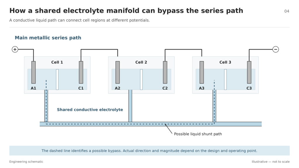
The sealing and compression checks apply to the filter-press assembly. The shunt-current risk applies where conductive electrolyte manifolds connect cells at different potentials.
Monopolar Alkaline Electrolyzer: Parallel Connection
Start at the positive DC terminal in Figure 1. Its busbar branches to both anodes. The negative busbar branches to both cathodes. Each cell spans the same two supply nodes. That is the electrical signature of a monopolar group.
The left panel shows the wiring separately from the physical hardware. A shared conductive wall can support anodes on both faces or cathodes on both faces while remaining tied to a single bus. For a drawing with several modules, trace the cell connections inside each module first. Then trace the connections between modules.
Bipolar Alkaline Electrolyzer: Series Connection
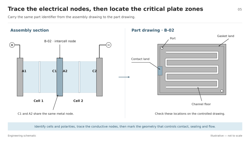
In the right panel, the positive terminal connects to the anode of Cell 1 and the negative terminal connects to the cathode of Cell 2. Between them, the conductive partition and its electrode contacts connect the cathode of Cell 1 to the anode of Cell 2. This intermediate node sits between two cells and has no branch to a supply bus in the simplified circuit.
The solid metal carries electrons across that link. Within each alkaline cell, hydroxide ions move from cathode to anode through the electrolyte-filled diaphragm. Track the metal links and the ionic paths separately when reading the cross-section.
Engineering Trade-Offs and Selection Guidance
How Series and Parallel Wiring Change the Power Supply
Suppose each of two identical cells runs at voltage V and current I. An ideal parallel group draws 2I at V. An ideal series stack draws I at 2V. Both arrangements deliver 2VI to the cells under these assumptions. The circuit rules for voltage and current explain how the load appears at the terminals.
Which Configuration Fits the Project?
Shortlist a monopolar layout if you need a low-voltage group or direct access to electrodes and the rectifier, busbars and joints can carry the total current. Check branch voltage drop at the design current and ask how a technician will reach, isolate and remove the affected assembly. Base the decision on the maintenance and wiring trade-offs of the tank-type design.
Shortlist a bipolar layout if a compact repeat stack, higher terminal voltage or shorter external wiring fits the project. Compare the actual gasket and compression design and ask for the expected shunt-current losses across the operating load range. Where adjacent cells share conductive electrolyte headers, part of the current can take a path through the liquid. Manifold geometry and electrolyte resistivity affect that loss.
Compare efficiency at a matched operating point. Set the hydrogen output, current density and duty cycle before comparing designs. Include external busbar and contact losses, electrolyte and diaphragm resistance, and gas-bubble effects in the cell voltage budget. For a plant-level comparison, use the same meter boundary for both systems and account for rectifier and auxiliary loads. Ask for specific energy consumption across the load range in kilowatt-hours per kilogram of hydrogen, with the measurement boundary stated.
How to Identify the Connection on an Assembly Drawing
- Locate and number the cells. Find the diaphragm inside each alkaline cell. Use the repeating frames and electrode pairs to mark cell extents. On a PEM drawing, locate the membrane electrode assembly, or MEA, inside each cell.
- Label the electrode sides. Mark A1 and C1 for the first cell, A2 and C2 for the second. Use the assembly notes or schematic to establish electrode roles.
- Trace the metallic paths. Start at the DC terminals and follow busbars, collectors, conductive partitions and intercell links. Record which electrodes share each electrical node. Check the wiring schematic if a connection is hidden in the cross-section.
- Classify the connection. If A1 and A2 share the positive bus and C1 and C2 share the negative bus, the illustrated cell group is monopolar and parallel. If a shared intercell conductor joins C1 to A2 and the supply connects at the ends, the illustrated stack is bipolar and series. Compare the node pattern with the two alkaline wiring layouts.
- Record each plate’s other functions. Use the fluid and mechanical sections to identify flow fields, cooling paths, sealing interfaces and support surfaces where present. Check which cells and circuits each face serves.
- Transfer the critical zones to the part drawing. Mark electrical contact lands, gasket lands, ports and channel floors. Where opposing channels overlap, call out the minimum remaining wall and front-to-back alignment.
If you are reviewing an etched metal plate, use the [Bipolar Plate Drawing Review Checklist](bipolar-plate-drawing-review-checklist.pdf) to record dimensions, interfaces and inspection requirements.
PEM Fuel-Cell Bipolar Plates in Context
In a conventional proton exchange membrane fuel cell stack, one face of the conductive bipolar plate serves the anode side of one MEA. The other face serves the cathode side of its neighbor. The plate collects and conducts current between the cells through its contacts with the gas diffusion layers. Hydrogen oxidation and oxygen reduction take place in the corresponding MEA catalyst layers.
A PEM fuel-cell plate can also separate neighboring cells and their reactant streams, route hydrogen and air or oxygen across the active areas, and support the stack mechanically. Its flow fields help carry product water out of the cathode side. Some plate assemblies also have internal channels for liquid coolant. These water, heat and support functions depend on the plate and stack design.
The distinction matters when specifying a part. Use the assembly to locate the electrical interfaces, then use the plate drawing to define fluid and mechanical features. See the separate guides to bipolar plate functions, fuel-cell plate materials, coatings, corrosion and contact resistance and inspection.
Design and Manufacturing Considerations
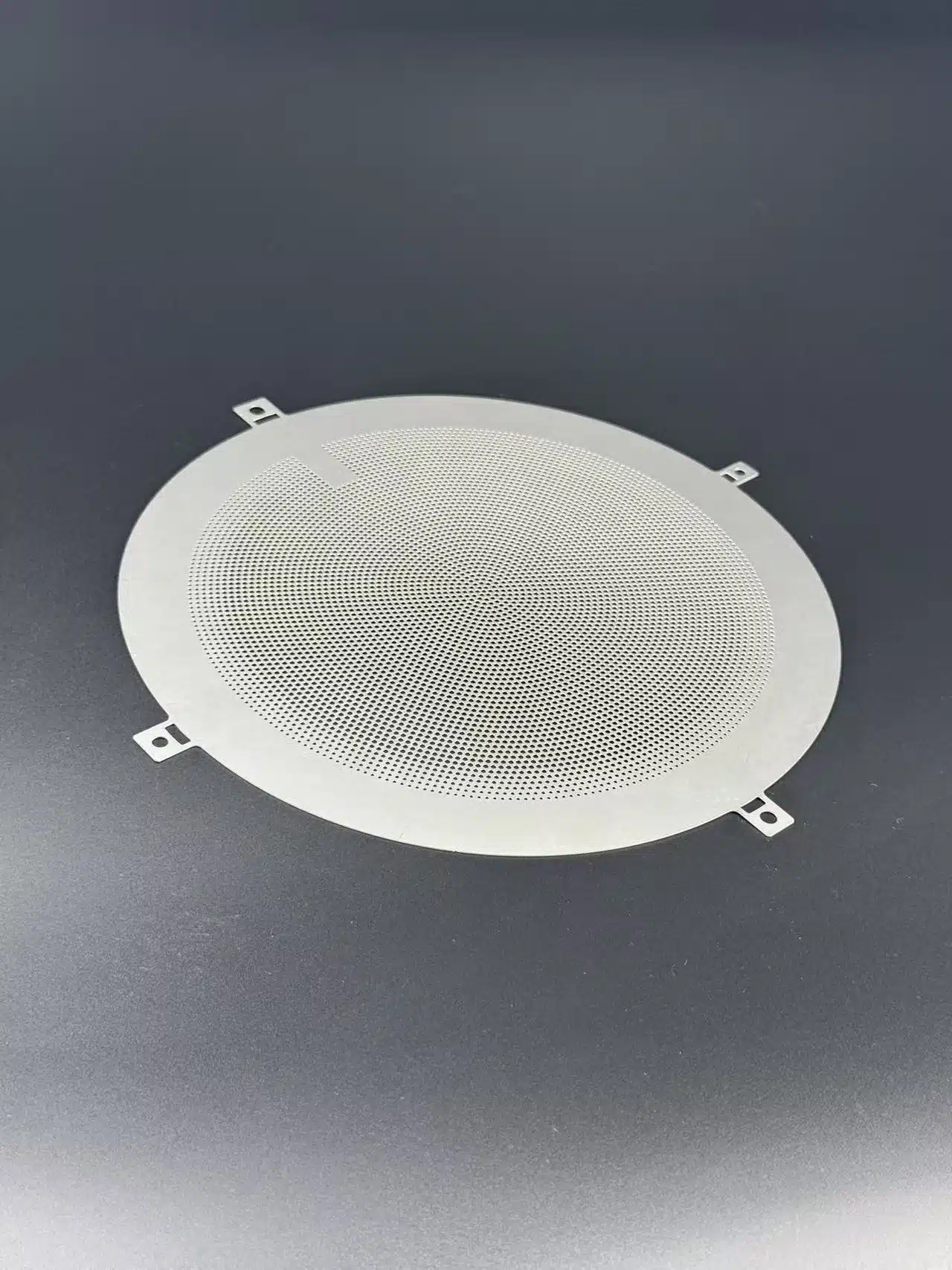
For chemically etched metal plates, specify the alloy, stock thickness, channel depths by face, front-to-back alignment and required wall after tolerances. Identify the surfaces that must contact electrically or seal. Set the surface finish, coating and inspection method for the zones where they matter. The etched flow-channel guide covers the drawing inputs for custom etched bipolar plates.
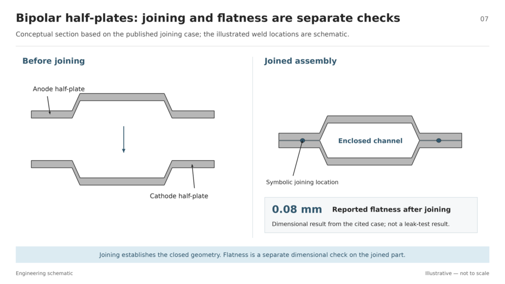
TMNetch manufacturing case. In a published plate-joining project, TMNetch welded bridge features on the anode and cathode plates to close the flow channels and reported 0.08 mm flatness. The joining operation established the closed geometry. The flatness result is a separate dimensional check on the joined assembly.
A separate TMNetch etched-plate design example uses 2.0 mm stock, with nominal depths of 0.6 mm and 0.4 mm on one face and 0.5 mm on the other. If the deepest recesses overlap, the nominal remaining wall is 0.9 mm. The tolerance review then uses minimum stock thickness and maximum permitted depths at that location. This calculation uses the published design dimensions.
Frequently Asked Questions
Is Every Flow-Field Plate a Bipolar Plate?
A flow-field plate takes its name from the channels that route fluid. It also functions as a bipolar plate when it makes the electrical connection between opposite electrode sides in adjacent cells. Check the assembly for that connection.
Can a PEM Stack Use an External Interconnect Instead of a Bipolar Plate?
Yes. A six-cell planar PEM fuel-cell prototype used spot-welded connections between neighboring anode and cathode terminals. That layout illustrates one way to connect planar cells in series through separate terminal links.
Why Are PEM Fuel Cells Usually Stacked in Series?
Series wiring adds the individual cell voltages to reach a usable DC output voltage. In a conventional stack, the bipolar plates provide the links between those cells.
Request a Bipolar Plate Drawing Review
Request a design-for-manufacturability review from TMNetch for a custom etched metal plate. List the application, alloy, sheet thickness, channel depths and target quantities in the form. Include a drawing link in Additional notes or ask how to send the assembly and part files. Ask for feedback on channel depth and remaining wall, material and thickness, critical tolerances and surface finish. Include the prototype quantity for a quote.