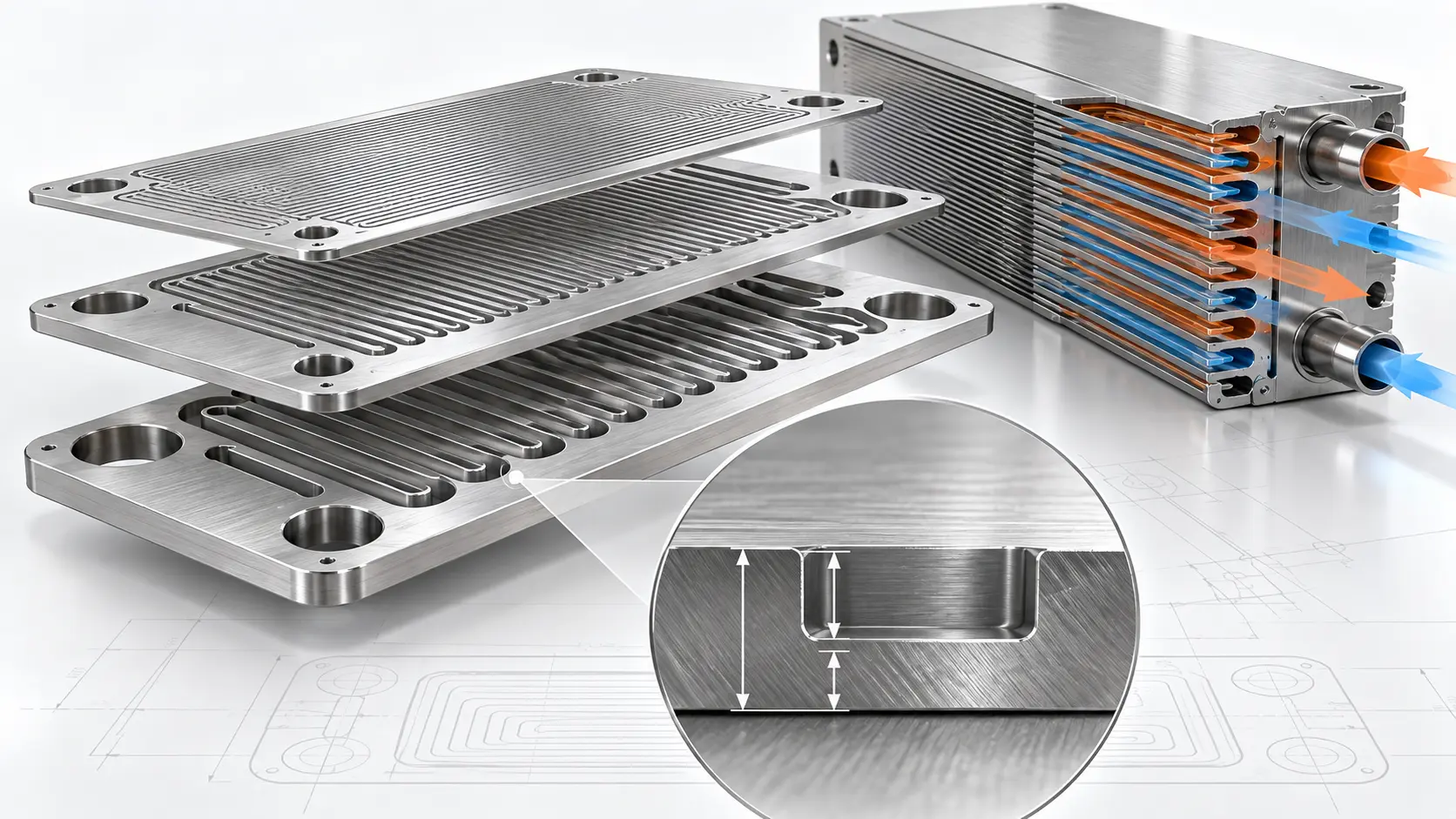

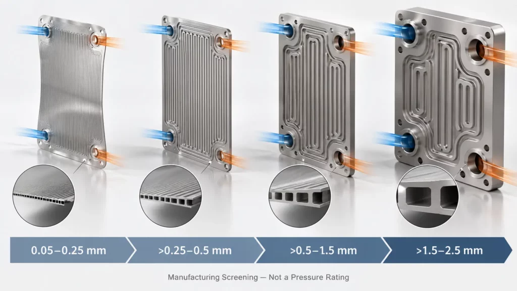
There is no single recommended thickness for every etched heat exchanger plate. As a manufacturing screening range, 0.05–0.5 mm can suit thin plates with fine, planar features, while 0.5–1.5 mm provides more material for deeper channels and stronger handling. Plates approaching 2–2.5 mm require closer review of etch depth, feature size, undercut, tolerance and cost. None of these ranges establishes the pressure rating of a finished exchanger.
The correct thickness must be developed with the channel geometry, remaining wall, alloy, joining method and operating conditions. That is why a chemical etching service should review the plate drawing together with the heat-exchanger requirements, not as an isolated sheet-metal part.
Key Takeaways
- Use 0.05–0.5 mm as a starting range for fine patterns, not as a pressure-design rule.
- Separate starting thickness, etched depth and residual wall thickness.
- Through-holes are constrained by stock thickness; partial-depth channels depend more directly on etch depth and process control.
- Verify pressure capability for the bonded core and completed exchanger.
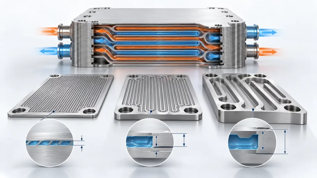
Three Dimensions Define an Etched Plate
Before selecting a gauge, engineers should define three different dimensions: tr = t0 − de
Where:
- t0 is the starting plate thickness;
- de is the single-sided etch depth;
- tr is the residual wall below the channel.
This distinction matters because the starting plate is not the final heat-transfer wall. An Argonne National Laboratory report on PCHE system modeling distinguishes channel, wall and ridge dimensions when representing PCHE geometry.
The residual wall affects conduction distance and local structural integrity. Channel pitch and ligament width determine the metal between adjacent passages. These dimensions must therefore be evaluated together.
A Practical Thickness Screening Framework
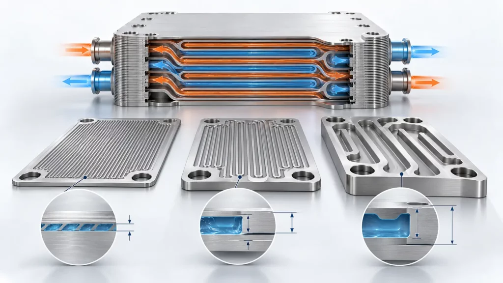
The following ranges are a DFM screening framework, not an industry standard. Public photochemical-machining guides show broad supplier capabilities: Fotofab publishes a sheet range of 0.005–2.286 mm, while Precision Micro describes 0.01–2.5 mm as a general range. Actual limits change with the alloy, plate size, feature pattern and required tolerance.
These bands describe a preliminary manufacturing discussion, not a thermal-hydraulic or pressure-design recommendation. A particular supplier may use a narrower or wider range.
| Starting thickness | Initial manufacturing assessment | Main questions |
|---|---|---|
| 0.05–0.25 mm | Strong candidate for thin shims, distribution layers and fine through-features | Can the foil remain flat and be handled through stacking and joining? |
| >0.25–0.5 mm | Useful starting band for fine etched flow plates | Is enough residual wall left below the required channel depth? |
| >0.5–1.5 mm | Candidate for more robust flow plates and many development-scale PCHE geometries | Do channel width, pitch and ligament scale appropriately with thickness and depth? |
| >1.5–2.5 mm | Specialist DFM review | Are the etch time, compensation, absolute tolerance and cost acceptable? |
| >2.5 mm | Special process or hybrid-manufacturing review | Should deep cavities or large profiles be machined or laser-cut instead? |
The lower end is not automatically better. Thin foil supports small through-features but is more sensitive to handling and distortion. One supplier guide also notes that selective-depth etching is not available for every thin foil design.
How Thickness Affects Through-Holes and Slots
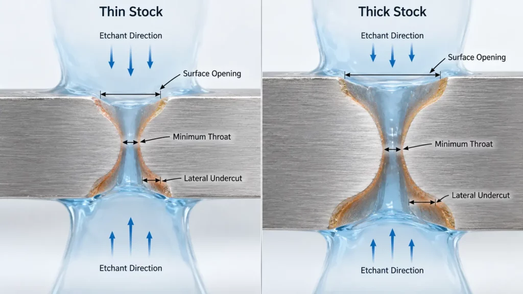
For a through-hole, the etchant must travel through the entire sheet. It also removes metal laterally beneath the photoresist. This lateral removal is called undercut, and it produces an etched wall that is not perfectly vertical.
Published supplier rules vary, but they consistently link minimum through-features to material thickness. Fotofab gives a typical hole or slot range of about 90%–120% of stock thickness, with a practical minimum of 0.102 mm. Other photochemical-machining guides use more conservative ratios, such as 1.1–1.25 times thickness or higher. These values are supplier planning rules rather than universal tolerances.
For example, the 90%–120% rule gives the following preliminary comparison:
| Plate thickness | Indicative through-hole or slot width |
|---|---|
| 0.20 mm | 0.18–0.24 mm |
| 0.50 mm | 0.45–0.60 mm |
| 1.00 mm | 0.90–1.20 mm |
| 2.00 mm | 1.80–2.40 mm |
These are not quotation tolerances. They show why a 0.3 mm port is a different problem in 0.2 mm and 2 mm sheet. Final dimensions need supplier review.
Partial-Depth Channels Follow a Different Rule
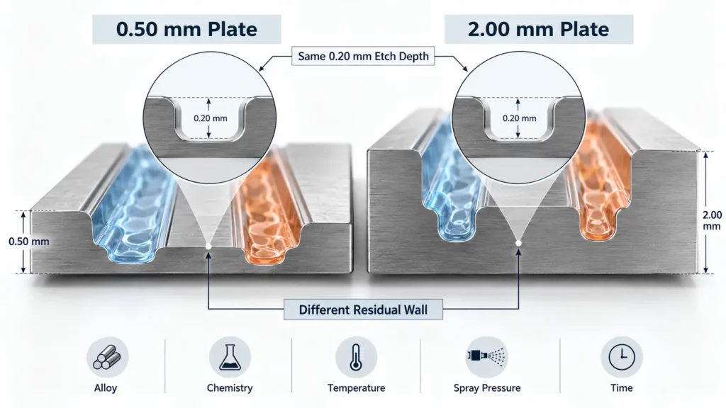
The statement “thicker plates always have more undercut” is incomplete. It is generally useful for through-etched features because the etchant must penetrate the full thickness. For a partial-depth channel, however, lateral etching is more directly related to the required depth and the controlled process window.
A peer-reviewed study on stainless-steel PCHE channels examined the effects of ferric-chloride concentration, phosphoric-acid concentration, temperature and spray pressure on etch rate, lateral erosion and surface roughness. The results show why total plate thickness alone cannot predict channel accuracy.
In plain terms, a 2 mm plate with a 0.2 mm channel does not automatically have four times the undercut of a 0.5 mm plate with the same depth. Remaining wall and stiffness differ, but channel formation still depends on etch depth, alloy and process control.
This is also why channel width, depth, pitch, ligament and plate thickness should be developed as one geometry. Our guide to photochemical etching for microchannel heat exchangers explains how these dimensions continue into stacking and bonding.
Worked Example: 0.50 mm Plate with a Half-Etched Channel
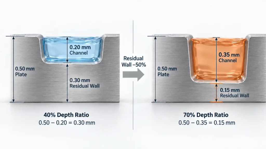
Consider a 316L stainless-steel plate with:
- starting thickness: 0.50 mm;
- nominal channel depth: 0.20 mm;
- residual wall: 0.30 mm;
- depth-to-thickness ratio: 40%.
Suppose the thermal-hydraulic design is changed to a 0.35 mm-deep channel without changing the plate gauge:
The depth ratio rises to 70%, while the residual wall falls by 50%. The revision changes flow area, load-bearing metal, the etching window and bonding behavior.
A 2026 study of etched pin-fin PCHE plates reported depth ratios above 67%, versus roughly 50% for the airfoil configurations discussed by the authors. It measured 4.5% lower average etch depth and 8.5% greater wall thickness. Modeled effectiveness changed by 0.34%, while pressure drop increased by 41%–45%. These design-specific results show that small geometric deviations can materially affect hydraulics.
For the example above, a 70% depth ratio should therefore trigger detailed manufacturing, structural and joining review. It should not be treated as an automatic pass or fail threshold.
Thickness, Heat Transfer and Pressure Are Different Questions
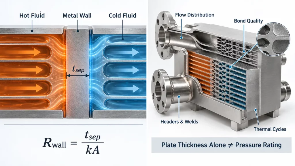
The conduction component of wall thermal resistance can be expressed as:
Here, tsep is the actual separating wall, k is thermal conductivity and A is area. Reducing the separating wall reduces this part of thermal resistance. It does not guarantee a proportional improvement in the complete exchanger because the fluid-side coefficients, flow distribution, fouling and contact or bond condition remain part of the total resistance.
Likewise, selecting a thicker plate does not by itself establish a higher pressure rating. A completed PCHE depends on residual walls, ligaments, material properties at temperature, diffusion-bond quality, headers, welds and cyclic loading. Research published in ASME’s Journal of Pressure Vessel Technology evaluates PCHE integrity through global thermomechanical response, detailed channel geometry and local stress analysis. A related ASME study of diffusion-bonded Alloy 800H also shows that bonding can alter material properties and must be considered when developing allowable stresses. Together, these studies show why plate thickness alone cannot establish the structural or pressure capability of a bonded PCHE core.
Alfa Laval publishes pressures up to 650 barG for its completed 316L PCHE configuration, produced through etching, stacking, diffusion bonding and welded assembly. That system rating does not validate a loose plate or thickness for another design.
Joining Can Change the Required Plate Geometry
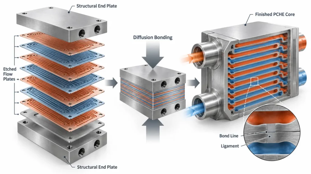
Etched plates become a heat-exchanger core only after a joining operation. Diffusion bonding uses elevated temperature and pressure to create a solid-state bond between stacked plates. Brazing introduces a filler metal, while welding is commonly used for plate pairs, edges, manifolds or larger assemblies.
Bonding pressure and temperature can change channel shape when walls or ligaments are insufficient. A recent PCHE review documents diffusion-bonding deformation and measurements across thousands of etched features, supporting the use of actual geometry in performance and reliability models.
One published high-temperature prototype used 1.6 mm Alloy 617 flow plates with approximately 2 mm semicircular channels and 2.5 mm pitch. The etched layers were diffusion bonded, while much thicker 12.7 mm end plates served the structural ends of the core. The example shows why flow-plate thickness and end-plate thickness should not be combined into one specification.
A Five-Step Method for Selecting Plate Thickness
1. Define the Plate Function
Identify whether the part is a through-etched distributor, partial-depth flow plate, bonded pressure boundary or structural end plate. Each function has a different controlling dimension.
2. Establish the Channel from the Duty
Define the fluids, temperatures, mass flow, allowable pressure drop, channel dimensions and fouling risk. Plate thickness should support the selected channel rather than replace the thermal-hydraulic calculation.
3. Calculate Residual Walls and Ligaments
Show channel depth, minimum residual wall, pitch, minimum ligament, edge margin and manifold transitions on the controlled drawing. Opposing channels require special attention to the metal separating the two circuits.
4. Run an Etching DFM Review
Review the alloy, stock tolerance, feature-to-thickness ratios, depth ratio, undercut compensation, panel size, flatness and inspection plan. For a broader process check, use the guide to photochemical etching tolerances, materials and limits.
5. Validate the Joined Core
Evaluate dimensional change after joining, bond integrity, pressure and thermal cycles, leak tightness and applicable equipment rules. The responsible exchanger designer must approve the finished pressure boundary.
When a Hybrid Process Is Better
Chemical etching is strongest for dense, repeated or partial-depth features. Laser cutting or CNC machining can be more practical for thick stock, large ports and deep cavities. A hybrid route may etch the channel field and laser-cut the profile. See chemical etching vs. laser cutting for heat exchanger plates for the process comparison.
What to Include in an RFQ
To review an etched heat exchanger plate, provide:
- alloy grade and material specification;
- starting thickness and stock tolerance;
- channel width, depth, pitch and minimum ligament;
- minimum residual wall;
- through-holes, ports and manifold geometry;
- plate length, width and flatness requirement;
- joining method and surface requirements;
- operating and design temperatures and pressures;
- pressure and thermal cycle requirements;
- prototype and annual quantities;
- inspection, material-certificate and reporting requirements.
TMNetch can review the etching manufacturability of the plate. Thermal sizing, joining qualification and pressure-equipment approval should remain with the responsible exchanger designer and qualified equipment manufacturer. For an initial assessment, submit the drawing and operating requirements.
Frequently Asked Questions
What Is the Best Thickness for an Etched Heat Exchanger Plate?
There is no universal best thickness. For early manufacturing screening, 0.05–0.5 mm can suit fine planar structures, 0.5–1.5 mm can support more robust flow plates, and 1.5–2.5 mm requires closer DFM review. The final value depends on channel depth, residual wall, alloy, joining and pressure design.
Can a 2.5 mm Heat Exchanger Plate Be Chemically Etched?
It may be feasible for some alloys and geometries, and public supplier guides extend to approximately 2.3–2.5 mm. At this thickness, small through-features, deep channels, absolute tolerance, etching time and cost need project-specific confirmation.
Is Plate Thickness the Same as the Heat-Transfer Wall?
Not necessarily. In a partial-depth etched plate, the heat-transfer wall may be the residual thickness below the channel. The stacking arrangement determines which remaining wall separates the hot and cold circuits.
Can Plate Thickness Determine the Pressure Rating?
No. Thickness is one design input. The completed core, bonds, manifolds, welds, material properties and loading history must be assessed and qualified as a system.