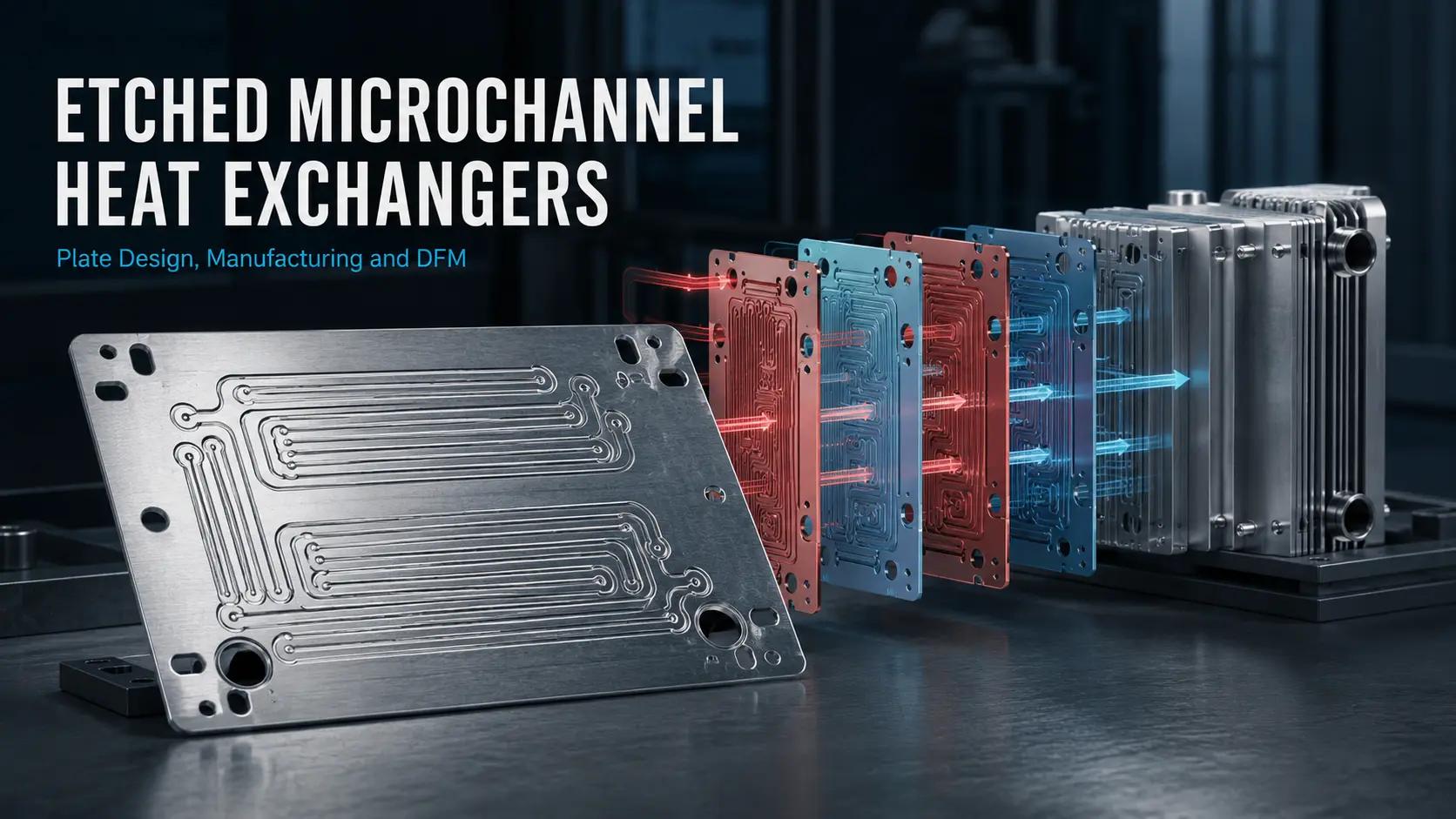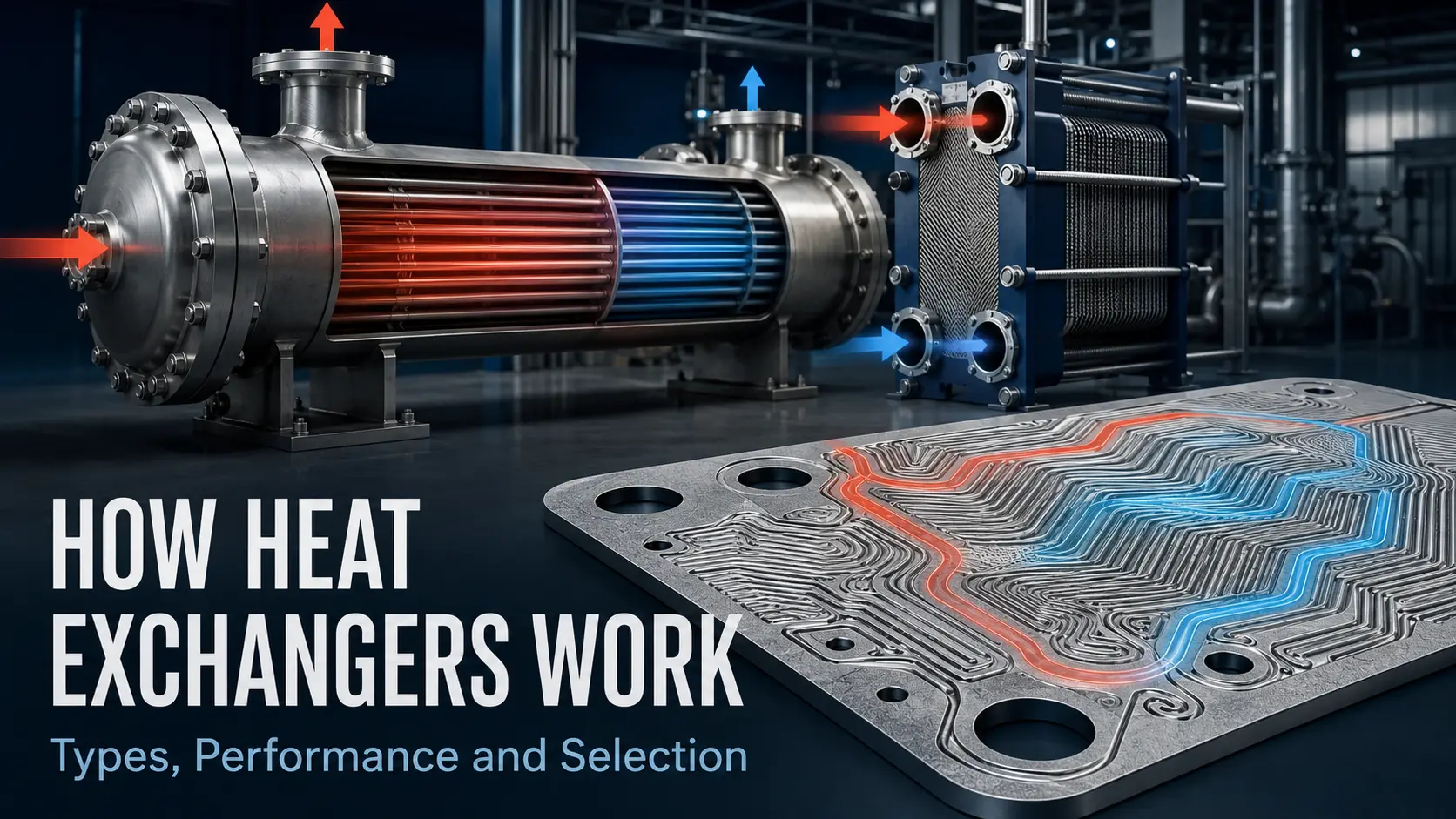

Photochemical etching, also called photochemical machining or photo chemical machining, creates metal plates with microchannels, ports and manifolds. In PCHE manufacturing, these etched heat exchanger plates are joined to form sealed fluid passages. Performance still depends on channel geometry, pressure drop, material and joint design, so development should begin with established photochemical machining tolerances and design limits.
Key Takeaways
- Photochemical machining creates open flow patterns. Diffusion bonding or brazing converts the plate stack into a sealed core.
- Smaller channels place more heat-transfer area inside a compact volume, but they can also increase pressure loss and fouling sensitivity.
- Channel width, depth, pitch, ligament width and plate thickness must be developed as one geometry.
- Published supplier figures are starting points for drawing review, not finished PCHE specifications.
What Is a Microchannel Heat Exchanger?
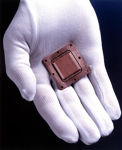
A microchannel heat exchanger transfers energy through small passages inside a compact core. The ASHRAE Handbook cites one classification in which hydraulic diameters of 10–200 μm are microchannels and 200 μm–3 mm are minichannels. Industrial usage is often broader.
A printed circuit heat exchanger, or PCHE, is more specific. Metal plates receive etched flow circuits before being stacked and diffusion bonded, as described by Idaho National Laboratory and an experimental study in Entropy. A microchannel heat sink instead transfers heat from a device into coolant. Some use semiconductor-etched silicon, so their manufacturing data do not directly describe a metal PCHE.
Why Do Microchannels Increase Heat-Transfer Density?
Small passages place more wetted surface inside a given core volume. Engineers commonly describe a non-circular passage with its hydraulic diameter:
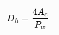
Here, is flow area and Pw is wetted perimeter. For a rectangular channel with width w and depth h:
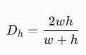
A smaller hydraulic diameter increases surface-area density, but can also raise frictional loss and pumping demand.
Zigzag channels can increase flow disturbance and heat transfer, but their turns add pressure loss. A US Department of Energy programme calculated 75% lower pressure loss for its airfoil-channel concept than for its zigzag reference at the same duty. Geometry must therefore be evaluated against both duty and allowable pressure drop.
The next question is which exchanger parts can carry these channels.
Which Etched Heat Exchanger Plates and Components Can Be Made?
Photochemical machining works on flat metal sheet and foil. One pattern can combine partial-depth channels, through-etched ports, a flow distribution manifold, alignment holes and the outside profile.
| Component | Etching relevance | Main design boundary |
|---|---|---|
| Microchannel flow plate | High | Width, depth and remaining wall interact |
| Manifold or distributor plate | High | Port geometry affects downstream flow distribution |
| Separator or shim layer | High | Sealing lands and flatness remain important |
| Cold-plate channel layer | High | Requires a compatible cover and joining route |
| Thin perforated flow baffle | Conditional | Suitable when it functions mainly as a patterned sheet |
| Thick baffle, end block or shell | Low | Structural loads extend beyond thin-sheet etching |
“Baffle” needs context. A thin distributor can be etched, while a thick shell-and-tube baffle may support tubes and carry mechanical loads under requirements.
Once the component is defined, its thermal geometry must be translated into an etchable pattern.
How Does Photochemical Machining Create Microchannels?
Heat duty, temperatures, flow rates, fluid properties, allowable pressure drop and fouling risk determine the number of passages and initial channel layout.
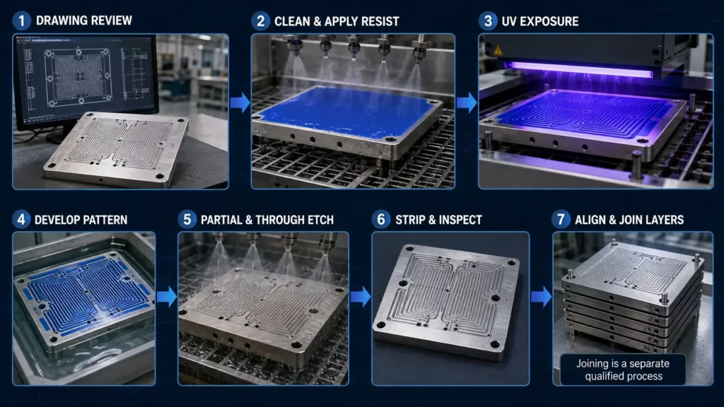
The manufacturing sequence then follows seven steps:
- Review the alloy, sheet thickness, flow circuit, ports, tolerances and future joining surfaces.
- Clean the sheet and apply photoresist.
- Transfer the CAD pattern with UV exposure and develop the resist.
- Etch the exposed metal. Partial etching forms channels; through-etching forms ports, holes and outlines.
- Remove the resist and clean the finished plate.
- Alternate and align the hot- and cold-side layers.
- Join the stack, then add the specified headers and connections.
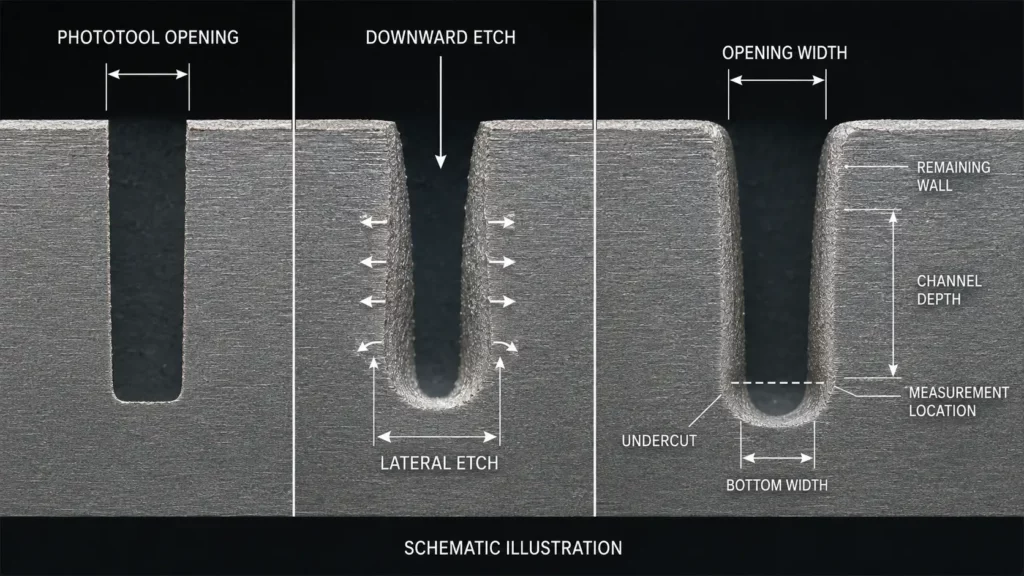
Etchant removes metal downward and sideways. This lateral removal is called undercut. It prevents a wet-etched groove from having the vertical walls of a milled slot. Research found that width, rolling direction, etchant temperature and time affected depth and undercut.
The finished cross-section may be rounded or tapered. Thermal and CFD models should use expected finished dimensions when this profile affects flow. Drawings should define opening width, bottom width, depth, remaining wall and measurement location. See the limitations of photochemical etching for related drawing requirements.
How Do Channel Dimensions Control Microchannel Plate Manufacturing?
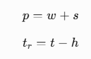
Four dimensions connect thermal design with microchannel plate manufacturing: width ww, depth hh, ligament width ss, and plate thickness tt. Pitch and remaining wall can be expressed as:
| Design change | Possible benefit | Main trade-off |
|---|---|---|
| Reduce channel width | More channels within the plate | Higher velocity, pressure loss and undercut sensitivity |
| Increase channel depth | More flow area in each passage | Less metal remains below the channel |
| Reduce ligament width | Greater channel density | Less support and joining area |
| Reduce plate thickness | Shorter conduction path and lower mass | Lower stiffness during handling and joining |
| Add bends or interruptions | More flow disturbance | Higher local loss and harder flow distribution |
The ligament separates channels, supports the plate and provides joining area. Narrowing it creates more passages but leaves less material for sealing and support.
One minimum-feature figure cannot define a metal microchannel fabrication project. Through-holes, shallow grooves and deep channels create different etching conditions, so finished dimensions must be reviewed with alloy, thickness, depth and measurement method.
After the individual plate is established, the project moves from channel geometry to core construction.
How Are Etched Plates Joined into a Diffusion-Bonded Heat Exchanger?
Hot- and cold-side plates can form counterflow, crossflow or a custom circuit. Their ports must align because a local restriction can redistribute flow among parallel channels.
Diffusion bonding joins clean surfaces under controlled temperature and pressure. Diffusion and grain growth develop across the interface without a conventional melted weld bead. The bonding cycle must match the alloy, surface and channel geometry.
A diffusion bonded heat exchanger is not automatically pressure-rated. A pressure-rated heat exchanger also requires structural calculations, qualified procedures and code-required examinations.
Brazing offers another joining route. It uses a lower-melting filler metal, so joint clearance, filler flow and thermal cycle must be controlled around small passages.
Material selection must therefore consider both channel formation and joining.
Which Metals Support Metal Microchannel Fabrication?
Material selection begins with the working fluids, temperature and pressure. Engineers must then check thermal cycling, etching response and compatibility with the intended bonding or brazing cycle. A metal with favorable thermal conductivity is not useful if it corrodes in service or cannot form a reliable joint.
| Material family | Why engineers consider it | Etching and joining question |
|---|---|---|
| 304L/316L stainless steel | Published PCHE research and commercial designs frequently use austenitic stainless steel. It offers a practical balance of corrosion resistance, strength and established fabrication experience. | Which grade suits both fluids, and will its properties remain acceptable after diffusion bonding? |
| Nickel and nickel alloys | Nickel-based alloys are considered for selected high-temperature or corrosive duties. Alloy 617, for example, has been studied in etched and diffusion-bonded PCHEs. | “Nickel alloy” is not one specification. The exact grade controls etching behavior, bonding conditions and service limits. |
| Titanium and titanium alloys | Titanium combines low density with resistance to selected corrosive media, making it relevant to weight-sensitive and chemically demanding systems. | The designer must confirm fluid compatibility, hydrogen exposure, surface preparation and the available joining route for the selected grade. |
| Aluminium alloys | Aluminium offers low density and high thermal conductivity, which can support lightweight compact exchangers. | Its stable oxide layer affects diffusion bonding, while alloy, filler flow and thermal cycle influence brazed designs. |
| Copper and copper alloys | Copper offers high thermal conductivity and can shorten conduction paths in suitable cold plates and compact thermal components. | Strength, corrosion behavior and compatibility with the selected bonding or brazing process must meet the operating conditions. |
TMNetch Capabilities and Project Boundaries
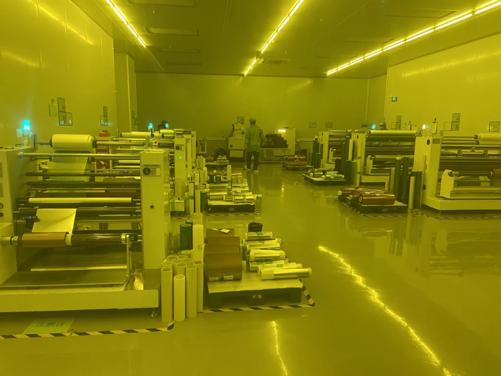
TMNetch lists a general processing thickness of 0.02–1.5 mm on its photo-etching page. It also lists features down to 0.05 mm for suitable geometries and critical tolerances as tight as ±0.025 mm. These figures depend on the material, thickness, geometry, depth and measurement method.
TMNetch also publishes information about diffusion welding and etched bipolar plate manufacturing. The page shows related work with double-sided and multiple-depth channels.
For heat exchanger design for manufacturability, an RFQ should include:
- Alloy, temper and certificate requirements
- Plate thickness and overall dimensions
- Channel width, depth, pitch and remaining wall
- Ports, manifold geometry and front-to-back registration
- Critical tolerances, flatness and surface requirements
- Intended joining process
- Working fluids, design temperature and pressure
- Prototype quantity and expected production volume
Frequently Asked Questions
Is photochemical machining the same as photo chemical machining?
Yes. Photochemical machining, photo chemical machining, photochemical etching and photo etching are commonly used for the same masked chemical metal-removal process. The spaced form is less common in current technical writing.
Can etched heat exchanger plates contain true microchannels?
Yes, when alloy, sheet thickness, channel depth, spacing and tolerance form a workable combination. The supplier should review the complete cross-section rather than only the nominal opening width.
Is every diffusion bonded heat exchanger a pressure-rated heat exchanger?
No. Diffusion bonding describes the joining route. A pressure rating also depends on structural design, qualified manufacturing, examination, testing and applicable construction rules.
What should a flow distribution manifold accomplish?
It should deliver the intended flow to parallel channels without excessive local loss or maldistribution. Port size, manifold shape and channel resistance must be evaluated as one hydraulic network.
Conclusion
Photochemical machining can turn a thermal flow concept into repeatable etched heat exchanger plates. Success depends on designing the channels, metal layers, manifold and joining route as one system.
Review the available photo etching service for custom flow plates or submit your drawing and operating conditions for a microchannel heat exchanger manufacturability review. For further design preparation, see the guide to photochemical etching tolerances and material limits. Thermal sizing, pressure design and equipment approval should remain with the responsible exchanger designer and qualified manufacturer.