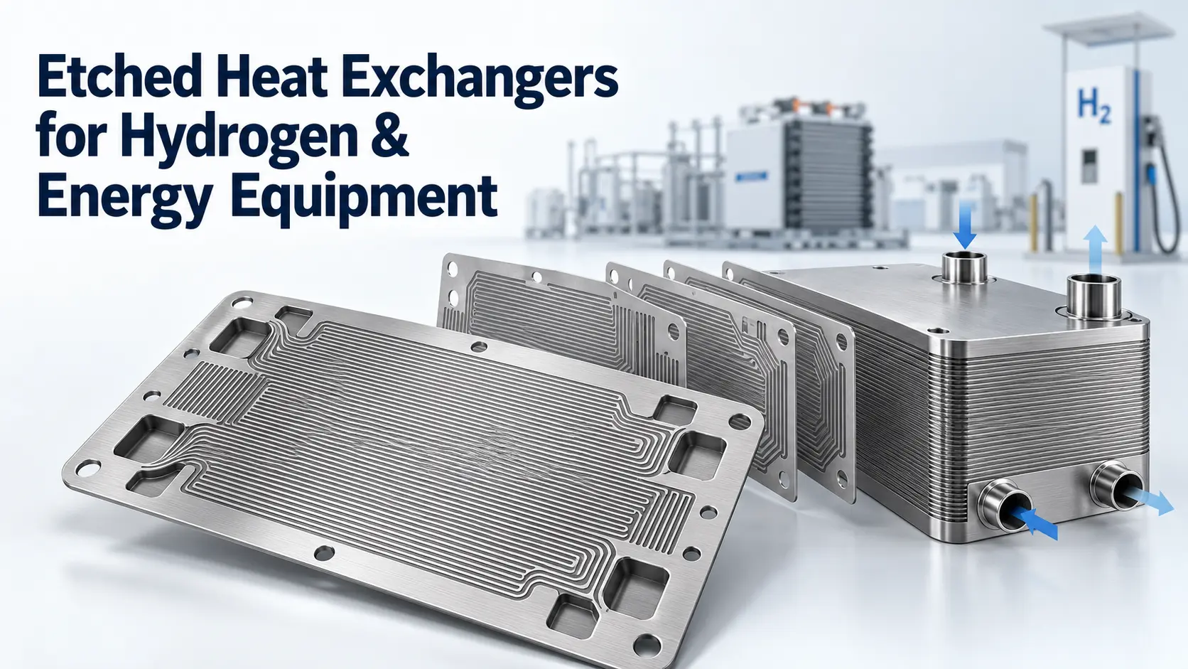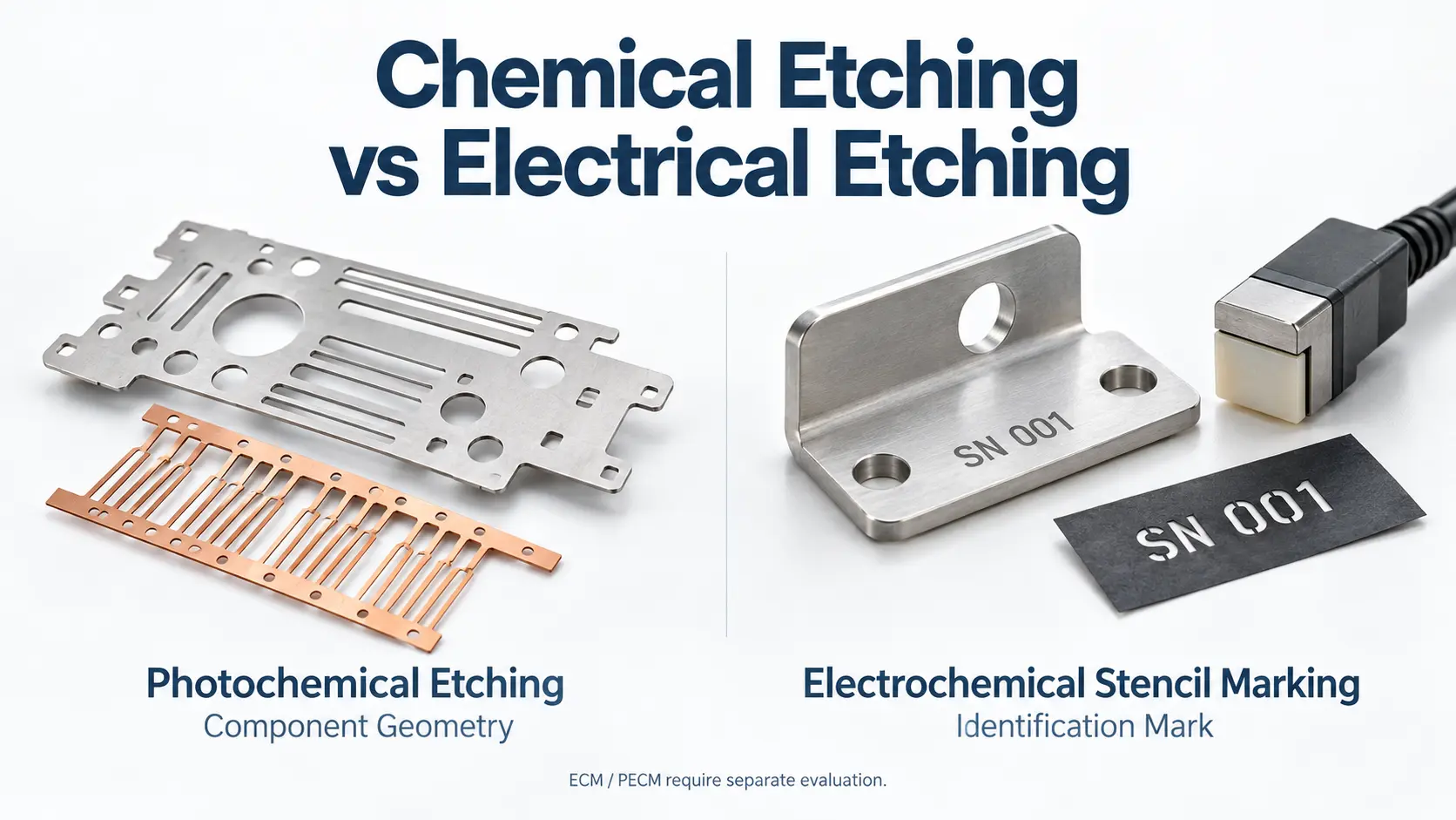

Chemical etching can produce flow plates and distribution layers for selected heat exchangers used in hydrogen and energy equipment. A printed circuit heat exchanger, or PCHE, combines patterned metal plates with diffusion bonding.
For buyers considering precision chemical etching services, the first question is where the component operates. A coolant plate, a hydrogen precooler and an electrolyzer bipolar plate have different duties. Their fluids, pressure conditions and joining requirements should guide the manufacturing review.
Key takeaways
- Identify the fluid touching each plate before selecting a material.
- Evaluate heat duty, flow distribution and pressure drop together.
- Specify the etched plate, joined core and completed exchanger separately.
- Confirm hydrogen compatibility and pressure-cycle requirements for the actual service.
Where Etched Heat Exchanger Plates Fit in Hydrogen Systems
An etched plate is one layer in a larger assembly. Its channels must work with the surrounding plates, ports and joints. In this PCHE development, plate fabrication, diffusion bonding and mechanical characterization are connected tasks.
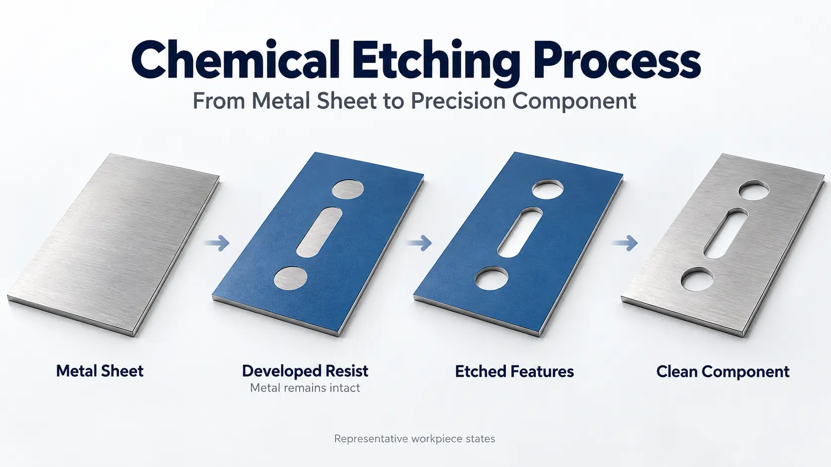
In photochemical machining, patterned photoresist protects selected metal while exposed areas are chemically removed. For heat-transfer components, the manufacturing drawing must translate the intended fluid circuit into defined plate features and joining surfaces.
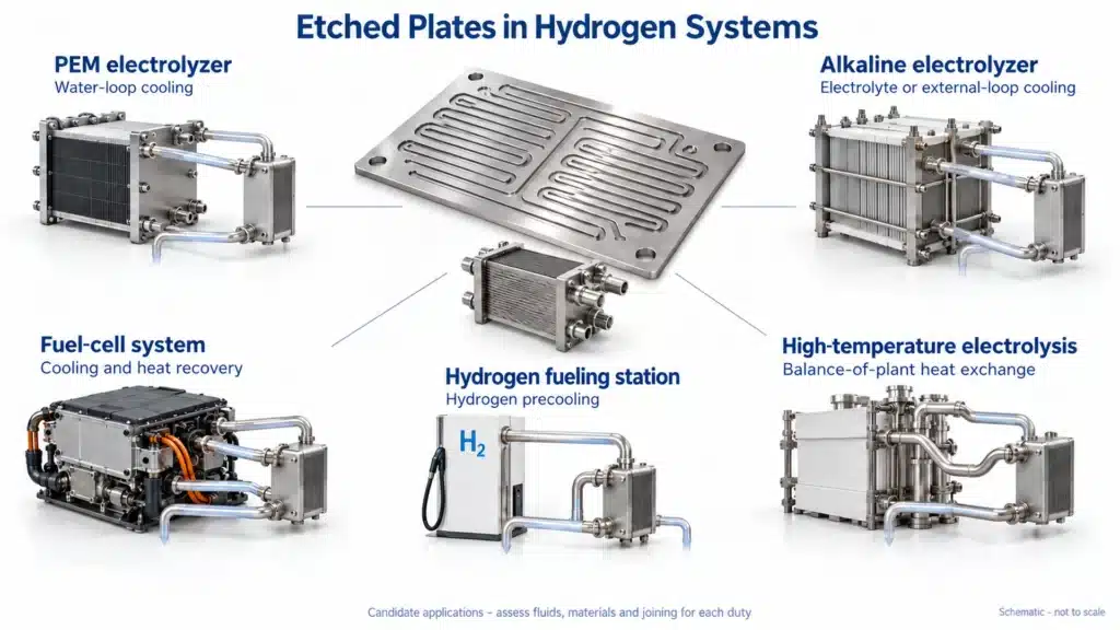
Use the following application map to begin a supplier discussion. The suggested components are candidates for assessment, rather than standard replacements for every exchanger.
| Equipment location | Thermal task | Candidate etched component |
|---|---|---|
| PEM electrolyzer cooling loop | Remove heat from circulating water | Flow-channel plate or distribution layer |
| Alkaline electrolyzer | Cool the electrolyte or an external loop | Chemically compatible heat-transfer layer |
| Fuel-cell system | Manage stack cooling or recover process heat | Coolant plate or recuperator layer |
| Hydrogen fueling station | Precool hydrogen before dispensing | PCHE flow plate and manifold layer |
| High-temperature electrolysis system | Exchange heat within the balance of plant | Qualified high-temperature alloy plate |
Electrolyzer thermal management can involve water-loop cooling for PEM systems and electrolyte cooling for alkaline systems. These are different fluid environments, even when both assemblies belong to hydrogen-production equipment.
Mark those environments on the process diagram before requesting a quote. For each plate, identify the fluid on each face and the destination of every port. This simple review connects the system description to the component drawing and gives the supplier a clearer basis for assessing manufacture.
Why Compact Channels Need Thermal and Hydraulic Design
Compactness must be evaluated alongside fluid distribution and cleaning access. Particulate fouling, channel-flow uniformity and cleaning-in-place are design considerations for diffusion-bonded microchannel exchangers. Channel size alone therefore provides an incomplete selection criterion.
For a manufacturing review, ask the designer to define heat duty and allowable pressure loss before optimizing the channel pattern.
Compare proposed geometries at the same inlet conditions and required duty. Record exchanger size, pressure loss and flow distribution together. That comparison makes the design decision reviewable: the team can see what a smaller core costs in hydraulic resistance, rather than judging the channel pattern by appearance.
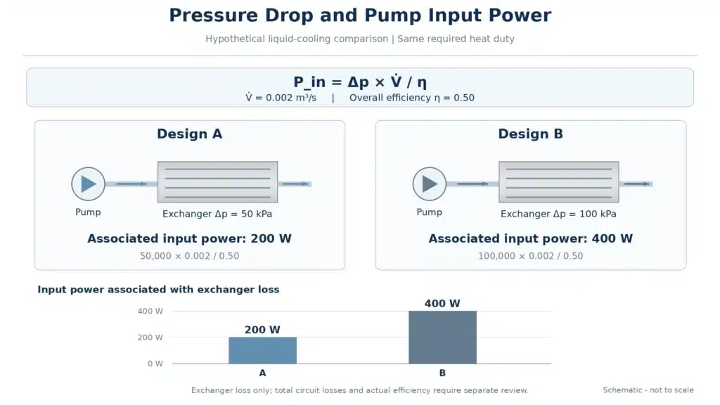
Consider a hypothetical liquid-cooling comparison. Both designs meet the same heat duty. Flow is 0.002 m³/s, and combined pump-and-motor efficiency is fixed at 0.50:
Input power = Pressure drop × Volume flow / Overall efficiency
| Design | Exchanger pressure drop | Input power associated with that loss |
|---|---|---|
| A | 50 kPa | 50,000 × 0.002 / 0.50 = 200 W |
| B | 100 kPa | 100,000 × 0.002 / 0.50 = 400 W |
This calculation uses the hydraulic-power relationship. It isolates exchanger resistance; actual pump selection must include the rest of the circuit and changes in efficiency.
For hydrogen thermal sizing, use enthalpy at the specified inlet and outlet states. Enthalpy, density, heat capacity and transport properties are available for selected fluid states. A constant-property liquid example should not be reused as a high-pressure gas calculation.
Applications in Electrolyzers, Fuel Cells and Hydrogen Conditioning
Electrolyzer Thermal Management
PEM electrolyzers typically operate around 70–90°C, while conventional alkaline systems operate around 60–90°C. These stack operating ranges help explain the thermal environment; the exchanger’s design temperature still requires a project specification.
A liquid-to-liquid exchanger can cool water associated with the PEM anode loop. Alkaline equipment can cool the circulating lye, with an external liquid-to-liquid arrangement as an alternative.
Before discussing etching, identify the exchanger’s position in that circuit. Record both fluids, their concentration or purity, and whether the specified inlet contains gas or liquid only.
Fuel-Cell Cooling and Heat Recovery
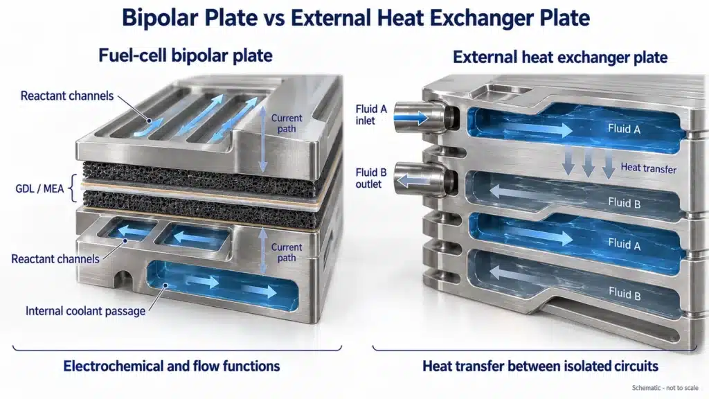
Fuel-cell thermal components include both internal cooling passages and separate heat exchangers. Bipolar plates distribute reactant gases, conduct electricity and support the stack. Additional internal channels may circulate liquid coolant. These combined functions distinguish a bipolar plate from an external heat-transfer plate.
A stainless steel air recuperator developed at PNNL was designed and tested in a fuel-cell demonstration system. Design duty was 3.5 kW, with heat-exchange effectiveness above 90%. Working prototypes used photochemical machining and high-temperature diffusion brazing.
That example supports etched-layer heat recovery. Its effectiveness figure describes the exchanger, rather than the fuel cell’s electrical efficiency.
Hydrogen Precooling and High-Temperature Duties
SAE J2601 includes H35/H70 pressure classes and T40/T30/T20 fuel-delivery temperature categories. Specify the required fueling conditions when evaluating a hydrogen precooling heat exchanger; −40°C is not a universal requirement for hydrogen equipment.
At the other temperature extreme, SOEC operation is around 650–850°C. High-temperature exchangers are included within the balance of plant. Material and joining decisions for these duties require separate assessment from low-temperature coolant service.
For hydrogen preheating or cooling after compression, describe the actual inlet and outlet states in the same way. Confirm whether condensation is expected and which stream contacts each surface. A generic request for a “hydrogen heat exchanger” leaves these manufacturing inputs unresolved.
Selecting Stainless Steel, Nickel Alloys and Titanium
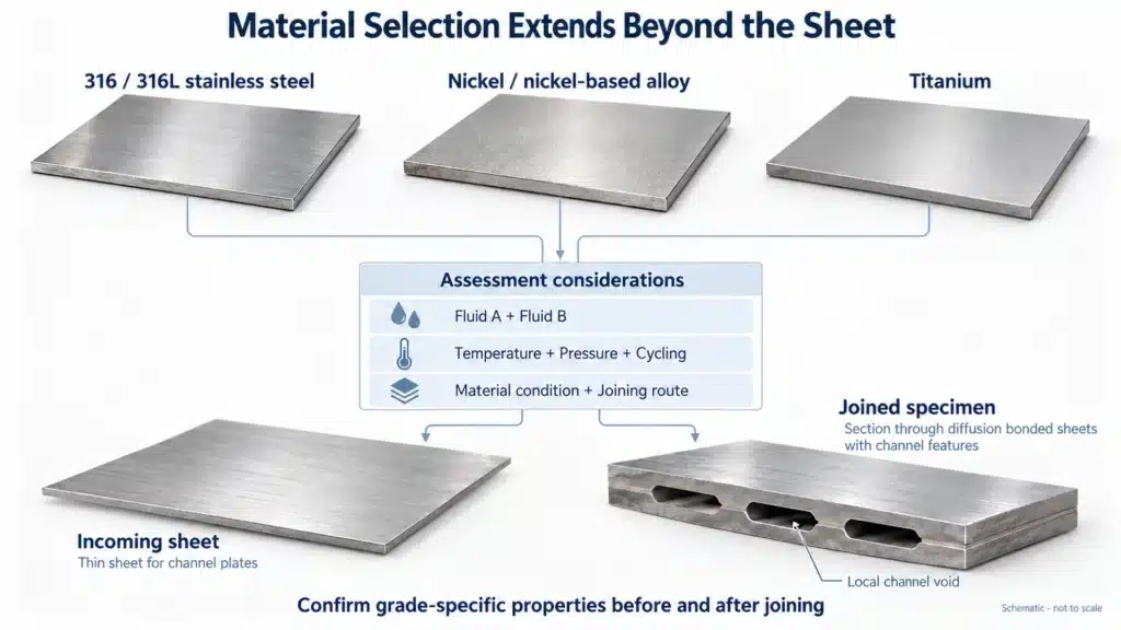
Material selection starts with the fluid environment and continues through fabrication. Deformation, fracture and fatigue properties under relevant hydrogen conditions are key assessment factors. Corrosion resistance alone does not complete that assessment.
| Material route | Evidence-based starting point | Question to resolve |
|---|---|---|
| 316/316L stainless steel | Grade-specific hydrogen properties | Are composition, material condition and joint properties suitable? |
| Nickel or nickel-based alloy | Nickel in alkaline electrolysis; Alloy 617 in PCHE development | Which exact alloy suits the chemical and temperature environment? |
| Titanium | Electrolysis applications and hydrogen-embrittlement considerations | Is this grade appropriate for the particular exposure and joining route? |
For stainless steel, preserve the specified grade throughout quotation and production. Composition and processing affect 316/316L hydrogen behavior.
Pure nickel, nickel-coated steel and Alloy 617 should be reviewed separately. Their use in different energy-system components does not establish interchangeable service limits.
Titanium also needs application-specific review. Titanium can experience hydrogen-related embrittlement. A titanium electrolysis component therefore provides no automatic qualification for a high-pressure hydrogen exchanger.
For every candidate, ask two separate questions: does the material suit both fluids, and does it retain the required properties after joining? Mechanical and microstructural characterization of bonded Alloy 617 specimens illustrates why the material review extends beyond the incoming sheet certificate.
TMNetch’s stainless steel etching, nickel alloy etching and titanium etching pages provide manufacturing entry points once the designer has identified candidate grades.
From Etched Plates to a Joined Heat Exchanger Core
For detailed channel preparation, see the guide to microchannel heat exchanger manufacturing. At the application level, the main task is to connect plate geometry with the intended joining process.
Diffusion bonding joins stacked, patterned shims under controlled conditions. Surface roughness and flatness are important variables because the surfaces need intimate contact.
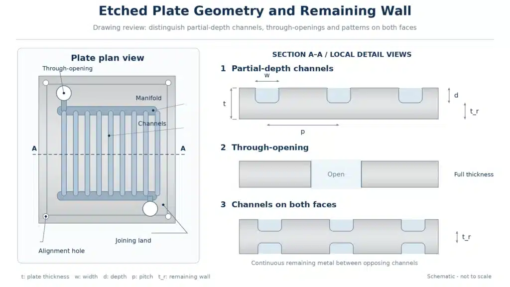
The drawing review should therefore cover channel dimensions, remaining metal, joining lands and surface requirements together. Confirm which areas must remain available for bonding and how the stack will be aligned.
Distinguish partial-depth channels from through-openings on the drawing. Identify the inspection datum and the surface from which channel depth is measured. If both faces contain channels, show their relative positions and the required remaining wall. These proposed drawing checks make the intended geometry explicit before the joining partner evaluates the stack.
Diffusion brazing is another route, as the PNNL example demonstrates. Keep its process specification separate from solid-state diffusion bonding. Successful fabrication requires the chosen joining procedure to match the actual alloy and channel structure.
Treat the supply chain as three defined deliverables: an inspected plate, an accepted joined core and a validated exchanger assembly. Agree who owns each stage before placing the component order.
Pressure Cycling, Corrosion and Leak Integrity
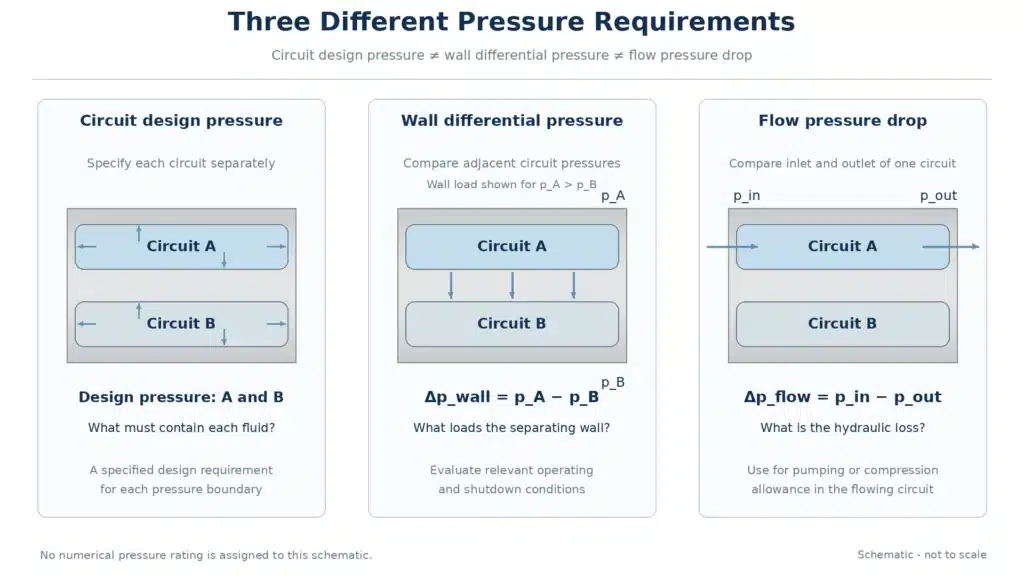
Pressure specifications should distinguish three quantities:
| Quantity | Meaning | Design question |
|---|---|---|
| Each side’s design pressure | Pressure each circuit must contain | What contains the fluid? |
| Differential pressure across the wall | Pressure difference between neighboring circuits | What loads the separating wall and joints? |
| Flow pressure drop | Inlet-to-outlet pressure loss in one circuit | What pumping or compression allowance is needed? |
Use this distinction as an RFQ checklist, including shutdown and abnormal operating cases.
Some hydrogen-precooling duties involve cooling at pressures up to 900 bar and a requirement to withstand more than 100,000 pressure cycles. Those are application and lifetime requirements, not a pressure rating for an arbitrary etched plate.
The project specification should address external leakage, leakage between circuits and material behavior under repeated loading. Hydrogen-affected fracture and fatigue properties should be evaluated alongside pressure containment.
Request evidence for each acceptance item separately. A dimensional report addresses plate geometry; a leak test addresses the specified leakage criterion; fatigue evidence addresses a defined loading history. Reviewing them as separate records prevents one successful check from being used to answer a different engineering question.
Select standards at the correct level. ISO 22734-1:2025 covers water-electrolysis hydrogen-generator safety. ISO 19880-1:2020 addresses gaseous-hydrogen fueling stations. The responsible designer must establish the applicable requirements and acceptance criteria.
What to Provide for a Manufacturing Review
Turn the material, joining and pressure questions into a controlled RFQ package:
- Material grade, condition and certificate requirements;
- Plate thickness, overall dimensions and production quantity;
- Channel width, depth, pitch and minimum remaining wall;
- Ports, manifold geometry and alignment features;
- Joining lands, flatness, surface and cleanliness requirements;
- Both fluids, flow rates, temperatures and design pressures;
- Heat duty, allowable pressure drops and operating-cycle profile;
- Intended joining route and inspection responsibilities.
This checklist brings together plate geometry, joining requirements and service conditions.
TMNetch lists fuel cells and heat exchangers among its energy and industrial applications. For an etched heat exchanger plate project, submit the drawing and operating conditions for a manufacturing review. Define the required plate delivery condition and identify the party responsible for core joining and equipment validation.
Frequently Asked Questions
Is stainless steel automatically suitable for hydrogen?
No. Hydrogen compatibility requires assessment of specific alloys and material conditions. Confirm the grade, processing history, temperature and loading conditions for the project.
Is titanium always the safer choice?
No. Titanium’s use in electrolysis does not establish suitability for every hydrogen exposure. Grade selection and hydrogen-related material behavior need review.
Does chemical etching determine exchanger pressure capability?
Etching defines plate features. Pressure capability also requires material assessment, joint qualification and structural verification under the applicable construction requirements.
Must every hydrogen heat exchanger cool to −40°C?
No. Several fueling temperature categories are defined in SAE J2601. Electrolyzer cooling, fuel-cell heat recovery and high-temperature electrolysis have different thermal duties.