Why the Bipolar Plate Manufacturing Process Matters
Bipolar plates often make up most of a PEM fuel cell stack’s mass and volume. According to published PEMFC reviews, bipolar plates can account for about 70–90% of total stack mass and volume, depending on stack design and material system. That is why the bipolar plate manufacturing process has a direct effect on stack weight, flow channel accuracy, contact resistance, sealing reliability, and final production cost.
Every manufacturing method creates a different balance between precision, tooling cost, design freedom, and volume scalability. A process that works well for 500,000 automotive plates per year may be a poor choice for a prototype that still needs three design changes. A method that gives excellent flow channel precision may not be suitable for very deep 3D formed structures.
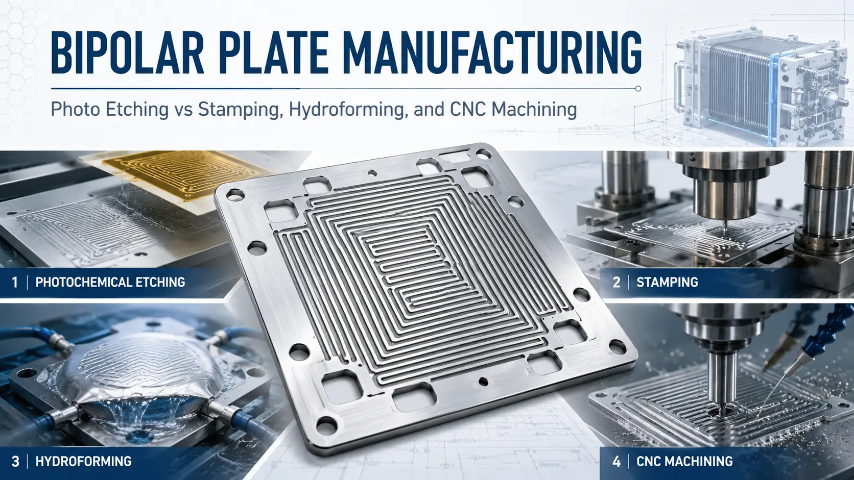
The right choice depends on where the project is in the development cycle. This guide compares photochemical etching, hydroforming, and CNC machining so engineers can match the process to the drawing, material, tolerance target, and annual volume.
If you are already evaluating custom bipolar plates for a fuel cell or electrolyzer project, the manufacturing method should be reviewed together with material, flow channel design, coating, and expected production volume.
What Is a Bipolar Plate and Why Does Manufacturing Precision Matter?
A bipolar plate is a functional plate used between cells in a fuel cell or electrolyzer stack. It is not only a separator plate. It manages gas flow, carries current, supports heat transfer, and helps keep the stack sealed.
In a PEM fuel cell, the bipolar plate has three main jobs. First, it distributes hydrogen and oxygen through flow channels. Second, it conducts electrons from one cell to the next. Third, it helps manage heat, water, and gas separation inside the stack.
Manufacturing precision matters because small dimensional errors can affect stack performance. If the channel depth varies too much, gas flow may become uneven. If the rib or wall area is inconsistent, the contact pressure may change across the active area. If the plate is not flat enough, contact resistance can increase. If the sealing edge is rough or distorted, leakage risk can rise.
Several dimensional parameters need close control during metal bipolar plate fabrication:
- Channel depth
- Channel width
- Rib or wall thickness
- Surface roughness, often measured as Ra
- Flatness and sealing edge quality
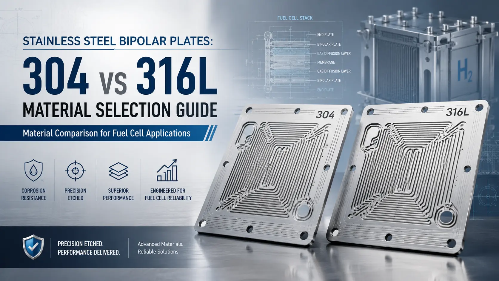
Common metallic materials include SS304, SS316L, Titanium Grade 1, Titanium Grade 2, aluminum alloys such as 1060 and 5052, and copper. Each material reacts differently to forming force, chemical exposure, coating, and stack operating conditions. That is why the manufacturing process should be selected together with the material, not after the material has already been fixed.
Key Factors Before Choosing a Bipolar Plate Manufacturing Process
Before comparing different bipolar plate fabrication methods, engineers should define several basic design and production factors. These factors decide whether photo etching, stamping, hydroforming, or CNC machining is the more practical route.
Material grade is the first factor. Stainless steel, titanium, aluminum, copper, and graphite all behave differently during etching, forming, machining, coating, and stack operation. For example, stainless steel bipolar plates are often selected for strength and cost balance, while titanium bipolar plates may be used when corrosion resistance is more critical.
Plate thickness also affects process choice. Thin metallic bipolar plates often benefit from photochemical etching because the process does not apply cutting force or forming pressure. Thicker plates, graphite plates, or one-off laboratory samples may be more suitable for CNC machining.
Channel depth and rib width are also important. Shallow, fine, and complex flow fields are often suitable for photo etched bipolar plates. Deeper 3D channel structures may require stamping, forming, or hydroforming, depending on the material and geometry.
Annual volume changes the cost logic. Photo etching is often practical for prototypes, pilot runs, and low-to-medium volume production because it avoids hard tooling. Stamping may become more cost-effective when the design is locked and the annual volume is high enough to justify die investment.
Coating requirement should be reviewed early. Conductive and corrosion-resistant coatings may be needed for PEM fuel cells or electrolyzers. The coating system should be selected according to the operating environment, not only the base metal.
Process 1: Photochemical Etching
How It Works
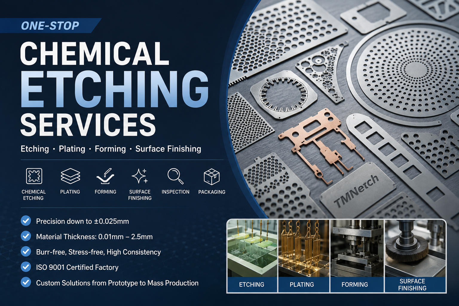
Photochemical etching, also called chemical etching or photo etching, is a subtractive metal manufacturing process. The supplier cleans the metal sheet, applies photoresist, exposes the pattern through a phototool film, develops the image, and removes the exposed metal with controlled chemistry.
The process does not use a punch, cutting tool, or laser beam to shape the flow field. This makes it a non-contact and low-stress method for thin metallic plates. After etching, the remaining photoresist is stripped, and the plate can move to cleaning, inspection, coating, forming, or assembly-related secondary steps.
For photochemical etching bipolar plates, the main value is not only fine detail. It is the ability to adjust flow field geometry quickly without making a hard die.
Advantages of Photochemical Etching for Bipolar Plates
Photo etching is especially useful during bipolar plate prototyping and early production. A design change usually requires a new phototool film, not a new stamping die. This can reduce both cost and lead time when the channel layout is still changing.
Under suitable design conditions, controlled-depth and double-sided etching can support multi-depth or asymmetric channel structures. For example, one side may need a different flow field depth from the other side. In some designs, local channel depth can also be adjusted through controlled exposure and etching strategy. The final feasibility depends on material thickness, channel depth, channel spacing, and tolerance requirement.
Photo etching also supports complex flow field geometries that are difficult or uneconomical for stamping. Fine serpentine channels, dense patterns, and asymmetric layouts can be transferred from CAD data to phototool film with high design flexibility. This is useful when engineers are testing new flow field concepts before committing to a locked design.
Another advantage is edge quality. Because the metal is dissolved instead of mechanically cut, chemical etching can produce burr-free edges without heat-affected zones. This helps reduce secondary deburring and avoids mechanical stress that could distort thin plates.
Photo etching is also strong for thin plate capability. Fine features and tolerances are evaluated according to material thickness, channel geometry, drawing requirements, and final inspection standards. Based on TMNetch process capability data, chemical etching can process metal sheets from 0.01 mm to 2.5 mm.
For many thin metallic bipolar plates, this process gives engineers a practical balance of precision, cost, and iteration speed. This is why photo etched bipolar plates are often used during prototype validation, pilot production, and custom bipolar plate fabrication before the design moves toward larger-scale production.
Limitations
Photo etching is not the right answer for every bipolar plate. Etch depth is limited by the starting sheet thickness and the required channel geometry. As a general design rule, deep cavities become more difficult as the depth approaches a large share of the material thickness.
It is also not the best method for very deep 3D corrugated structures. If the design requires large out-of-plane forming, stamping or hydroforming may be more suitable.
Chemical etching also requires proper waste treatment, bath control, and environmental management. The etchant condition, temperature, spray pressure, and exposure time must be controlled to maintain stable fuel cell bipolar plate tolerances.
Coating should be evaluated separately. Conductive and corrosion-resistant coatings may be needed for PEM fuel cells or electrolyzers, but coating choice depends on the electrochemical environment. Fuel cell and electrolyzer applications should not be treated as the same coating problem.
If the bipolar plate requires conductive or corrosion-resistant surface treatment, metal plating services should be reviewed together with the base material and stack operating environment.
Best Fit
Photo etching is a strong fit for R&D prototypes, pilot runs, and low-to-medium volume production where the design still needs flexibility. It is also suitable for thin metallic plates, fine flow fields, double-sided patterns, asymmetric flow channels, and projects where prototype-to-production continuity matters.
For many development-stage PEM fuel cell bipolar plates and electrolyzer plates, photo etching keeps the process route stable while the design is still changing. That can reduce the cost and time lost during repeated requalification.
Process 2: Stamping
How It Works
Stamping forms a metal blank by pressing it between a punch and die. For bipolar plates, progressive die stamping may be used to form corrugated flow channels through a series of stations.
This is a mechanical forming process. The material is shaped by force, so the die design, press control, lubrication, and springback compensation all affect the final plate.
Advantages of Stamping for Bipolar Plates
Stamping is one of the strongest processes for very high-volume production. Once the design is frozen and the die set is validated, stamping can produce parts at high speed with a very low per-unit forming cost.
This makes stamping attractive for automotive-scale programs. If a fuel cell vehicle platform needs hundreds of thousands or millions of bipolar plates per year, a validated stamping line can spread the tooling cost across a large production volume.
Stamping is also a mature sheet metal process. Suppliers understand die design, press selection, coil feeding, forming simulation, and quality control. For simple or repeated channel geometries, it can be a practical production route.
For projects that have completed flow field validation, precision metal stamping services may become a practical option when annual demand is high enough to justify tooling investment.
Limitations
The main weakness of stamping is tooling commitment. A bipolar plate stamping die can be expensive, and the final cost depends on the plate size, channel complexity, number of stations, material, and validation requirements. For complex bipolar plate programs, die cost can reach tens of thousands of dollars or much more.
Design changes after tooling are costly and slow. If the channel depth, pitch, active area, or sealing edge changes, the die may need modification or replacement. This makes stamping a poor fit when the project is still in R&D or pilot validation.
Stamping also has geometry limits. It works best for formed patterns that can be created through controlled deformation. Fine flow fields, local depth variation, and asymmetric channel layouts may be difficult or uneconomical.
Mechanical forming can also introduce springback, wall thinning, local stress, and micro-cracking risk. These issues become more important with hard or less ductile materials, including some titanium designs. For tight fuel cell bipolar plate tolerances, the forming process needs strong simulation, tooling correction, and inspection control.
Best Fit
Stamping is best for high-volume production with a locked and validated design. It is not the best starting point for a bipolar plate prototype, unless the program has already completed flow field validation and expects very large annual demand.
For many projects, a practical path is to use photo etching for prototypes and pilot builds, then evaluate stamping later if the design becomes stable and the annual volume justifies hard tooling.
Process 3: Hydroforming
How It Works
Hydroforming uses high-pressure fluid to press a metal sheet into the target channel geometry. For bipolar plates, sheet hydroforming is more relevant than tube hydroforming because the product starts from a flat or thin metal sheet.
The fluid pressure helps distribute forming force across the sheet. This can reduce some local forming problems compared with conventional punch and die stamping.
Advantages of Hydroforming for Bipolar Plates
Hydroforming can produce moderately complex 3D channel geometries. It may also support more uniform wall thickness distribution than conventional stamping in some designs. This can be valuable when channel depth, wall thickness, and sealing quality must stay stable across the active area.
For some titanium bipolar plates, hydroforming may be more suitable than conventional stamping because fluid pressure can reduce localized forming stress. Titanium is attractive because of its corrosion resistance, but it can be more difficult to form than stainless steel.
Hydroforming may also reduce springback in certain shapes and improve surface finish compared with more aggressive mechanical forming. These benefits depend on material grade, sheet thickness, channel depth, pressure control, and die design.
Limitations
Hydroforming still needs tooling. It does not remove the need for process development, forming simulation, and fixture validation. Equipment cost is also high, so it is usually used by well-resourced suppliers or programs with clear production justification.
Cycle time is typically slower than high-speed stamping. This makes hydroforming less attractive for very large annual volume unless the part design specifically needs its forming advantages.
Very thin materials can also be difficult to form reliably. If the plate is under 0.1 mm, handling, wrinkling, tearing, and thickness variation become serious concerns.
Hydroforming is generally less common than stamping for high-volume commercial metallic bipolar plate production. It can be a good technical option for specific formed structures, but supplier availability, equipment capability, tooling cost, and production readiness should be checked early.
Best Fit
Hydroforming is a good fit for medium-volume metallic bipolar plates that need formed 3D channels and tight wall thickness control. It is worth considering when titanium is required, the channel depth is too high for etching, and the geometry benefits from fluid-based forming.
For shallow, fine, or highly detailed flow fields, photo etching may still be the better option.
Process 4: CNC Machining
How It Works
CNC machining removes material from a billet, block, or sheet with rotating cutting tools. For bipolar plates, CNC milling can create flow channels directly from CAD data.
The process does not need a stamping die or phototool film. The main requirements are machine time, cutting tools, workholding, programming, and inspection.
Advantages
CNC machining offers high design freedom for one-off parts. Engineers can create deep channels, special test features, and complex 3D surfaces without investing in hard tooling.
It is also useful for laboratory samples when the goal is to test a flow field concept, sealing method, or assembly structure. For thick plates and graphite bipolar plates, CNC machining may be the most practical option.
Machining is especially useful when the design is not intended for production. If the team only needs one or two feasibility samples, the higher per-part cost may be acceptable.
Limitations
CNC machining is not a scalable route for most thin metallic bipolar plates. The production rate is slow because each channel must be cut by tool movement. The larger and more complex the active area, the longer the cycle time becomes.
Thin wall structures are also difficult to machine. Sub-millimeter ribs, thin walls, and unsupported plate areas can deform, vibrate, or break during cutting. The risk increases when the plate is thin, the channel pattern is dense, or the workholding is not stable. Cutting force can also affect surface integrity and dimensional consistency.
Tool wear creates another issue. As tools wear, surface finish and dimensional accuracy may drift. This makes batch-to-batch consistency harder to maintain at scale.
The final limitation is cost. CNC machining may be acceptable for lab-scale samples, but it becomes expensive for production quantities. For most metal bipolar plate fabrication projects, it is a prototype-only or research-only method.
Best Fit
CNC machining is best for laboratory prototypes, feasibility samples, thick plates, graphite plate machining, and very small batches. It is not the best route when the project needs thin metal plates, stable volume production, or low per-unit cost.
Bipolar Plate Manufacturing Process Comparison Table
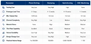
These values are useful for early process screening. Final selection should be based on the drawing, material thickness, channel depth, annual volume, tolerance target, and coating requirement. If you need help mapping your specifications to the right process, TMNetch can review your bipolar plate design before tooling or production decisions are made.
How to Choose the Right Bipolar Plate Manufacturing Process
If you need a working prototype or an early validation batch, photo etching is usually one of the first processes to evaluate. It avoids hard tooling and can convert CAD flow field data into physical plates quickly. This is useful when the goal is to test channel performance, sealing behavior, coating compatibility, or stack assembly.
If the design is locked and the annual volume is high, stamping may become the best long-term production method. The high die cost can be justified when the volume is large enough and the flow field geometry is suitable for forming. Even then, photo etching can still be useful for prototype and pilot phases before the final die is built.
If the plate requires deeper formed channels, out-of-plane features, or specific titanium forming performance, hydroforming and stamping should both be reviewed. Hydroforming may work better for certain 3D formed structures, while stamping may offer better cycle time after tooling is validated.
If the project only needs one or two lab samples, CNC machining or photo etching may both work. CNC machining is useful for thick plates, graphite bipolar plates, and special test features. Photo etching is usually better for thin metallic plates with fine flow fields.
If the design needs dual-depth channels, asymmetric flow fields, dense channel patterns, or fast design changes, photo etching is often the more practical choice. The key principle is simple: the right bipolar plate manufacturing process depends on the development stage, drawing requirements, material, and production volume.
Why Photochemical Etching Is Often Preferred for Bipolar Plate Development
For development-stage metallic bipolar plates, the main value of photochemical etching is flexibility under engineering control. It allows engineers to revise channel geometry without committing to hard tooling too early.
This is especially important for bipolar plate flow channel precision. A small change in channel width, depth, rib width, or inlet structure can affect pressure drop, gas distribution, and water behavior. During R&D, those details often change after stack testing.
Photo etching also supports prototype-to-pilot continuity. The same core process route can be used from early samples to low or medium volume production. This reduces the process gap between the first prototype and the first production-intent batch.
Material compatibility is another advantage. Chemical etching can process stainless steel, titanium, aluminum, copper, nickel, and related alloys under controlled conditions. This helps engineers compare different metallic bipolar plate materials without changing to a completely different manufacturing route.
For stainless steel bipolar plates, etching can support fine channel geometry and clean edge quality. For titanium, it can avoid the forming stress that may appear in mechanical processes. For aluminum or copper, it can support lightweight or high-conductivity plate concepts when corrosion protection and coating are properly considered.
For stainless steel bipolar plate projects, stainless steel etching can be reviewed when the design needs fine channels, clean edges, and low mechanical stress.
For many thin metallic bipolar plate projects in the prototype, pilot, and medium-volume stages, photochemical etching can provide a strong balance between precision, iteration speed, and cost control. It is especially valuable when the flow field design is still changing or when the plate requires fine, shallow, or asymmetric channel patterns.
TMNetch is a precision metal etching manufacturer that supports custom bipolar plate fabrication for stainless steel, titanium, aluminum, copper, nickel, and related alloys. For fuel cell and electrolyzer projects, the company can support photo etched bipolar plates, dual-sided etching, flow field pattern review, and prototype-to-pilot production support.
Based on TMNetch process capability data, chemical etching can process metal sheets from 0.01 mm to 2.5 mm. The company also supports prototype turnaround in as fast as 3 days, ISO 9001:2015 certified process control, and coating options such as platinum or MMO when the application requires them.
Coating selection should always be checked against the fuel cell or electrolyzer operating environment. A reliable bipolar plate supplier should review the material, flow channel geometry, coating requirement, tolerance target, and annual volume before confirming the final process route.
FAQ
What is the best process for bipolar plate prototyping?
Photo etching is often the best process for thin metallic bipolar plate prototyping. It has low tooling cost, short lead time, and high design flexibility. Engineers can revise the flow field pattern without rebuilding a hard die.
CNC machining can also work for one-off lab samples, especially for graphite or thick plates. However, it is usually too slow and costly for repeated thin metal prototypes.
What is the most common manufacturing process for metallic bipolar plates?
There is no single best process for all metallic bipolar plates. Stamping is often considered for high-volume production after the design is locked. Photochemical etching is often used for prototypes, pilot runs, fine flow fields, and low-to-medium volume production. Hydroforming may be suitable for some formed 3D channel structures, while CNC machining is mainly used for lab samples or graphite plates.
Is photochemical etching better than stamping for bipolar plates?
Photochemical etching is usually better for prototypes, design iteration, fine flow fields, and low-to-medium volume production. Stamping is usually better for very high-volume production after the design is fully validated.
The key difference is tooling commitment. Photo etching uses phototool film, while stamping requires hard dies. That makes bipolar plate stamping vs etching mainly a question of development stage and annual volume.
What tolerances matter most in fuel cell bipolar plates?
The most important fuel cell bipolar plate tolerances include channel depth, channel width, rib width, flatness, surface roughness, and sealing edge accuracy. These dimensions affect gas flow, contact resistance, stack compression, and leakage risk.
The required tolerance depends on plate size, material thickness, stack pressure, gasket design, and coating thickness. A supplier should review the drawing before confirming the final tolerance target.
Can titanium bipolar plates be chemically etched?
Yes, titanium bipolar plates can be chemically etched under controlled process conditions. Titanium is corrosion-resistant but more difficult to process than many stainless steels, so etchant control, cleaning, and inspection are important.
Photo etching is useful when the titanium plate needs shallow, fine, or complex channels. Hydroforming may be considered when the design needs deeper formed 3D channels.
When should I choose stamping instead of photo etching?
Choose stamping when the bipolar plate design is locked, the flow field geometry is suitable for forming, and the annual volume is high enough to justify hard tooling. This is common in automotive-scale production.
Do not start with stamping if the design still needs several rounds of testing. In that case, photo etching can reduce early tooling risk and help validate the design before mass production.
Conclusion
Photochemical etching, stamping, hydroforming, and CNC machining all have a place in bipolar plate manufacturing. Photo etching is often a strong choice for thin metallic bipolar plates that need fine flow fields, fast design changes, burr-free edges, and prototype-to-pilot flexibility. Stamping is usually better after the design is locked and the annual volume is high enough to justify hard tooling. Hydroforming fits some formed titanium or 3D channel designs, while CNC machining is mainly used for lab samples, graphite plates, and very small batches.
For many development-stage and medium-volume metallic bipolar plate projects, photochemical etching offers a practical balance of precision, flexibility, and cost control. Send your bipolar plate drawing to TMNetch for a free technical review before committing to tooling or production. The review can help confirm material selection, channel feasibility, tolerance targets, coating requirements, and the most suitable bipolar plate manufacturing process.