
Quick answer:
Manufacturers turn an approved hole-pattern drawing into a grille by checking the material and thickness, preparing tooling or phototooling, forming the openings, and inspecting the part before and after finishing. For a perforated metal speaker grill, define hole size, pitch, minimum web width, and the condition in which each feature will be measured.
The useful question at each stage is whether the part still matches the approved drawing. Consider an illustrative sample whose holes pass inspection before coating. If some openings appear restricted afterward, compare the two conditions using the same measurement region. That comparison gives the reviewer a place to start investigating.
CAD Design of the Hole Pattern
Lock the Drawing Revision and Critical Dimensions
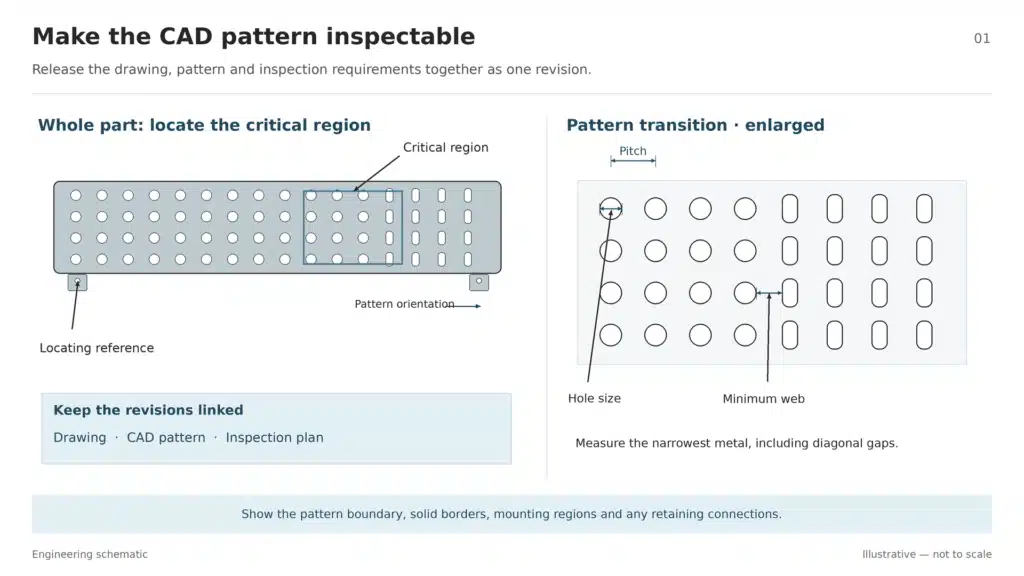
Release the drawing, CAD pattern, and inspection requirements as one revision. Identify the hole pattern relative to the features that locate the part. For a pattern with gradients, irregular holes, or solid borders, mark the critical regions explicitly.
| Drawing input | What to settle before processing |
|---|---|
| Material and thickness | Alloy, material condition, stock thickness, and any surface requirements |
| Hole size and shape | Dimensions for round or shaped openings, plus the surface or cross-section where each dimension applies |
| Pitch and position | Center-to-center spacing, pattern orientation, and locating references |
| Minimum web width | The narrowest strip of metal between adjacent openings, including irregular or diagonal features |
| Pattern boundary | Solid margins, interrupted holes, mounting areas, and any retaining connections |
| Open area | Approved target, reference region, and the processing stage at which it will be checked |
If the opening varies through the thickness, distinguish the front and rear openings from any required internal dimension. In photo etching, lateral metal removal can produce undercut and a nonparallel hole wall. Define which dimension governs acceptance before producing the sample.
Review Feasibility Before Releasing the Pattern
Review the smallest opening and narrowest web against the actual alloy, thickness, and route. In photochemical etching, opening size and web width are related to stock thickness.
Ask the supplier to mark any proposed change on the drawing. Once approved, carry that revision into the production pattern and inspection plan. Use the speaker grille design guide if open-area targets or mounting requirements still need to be defined.
Tools and Machinery for Micro-Hole Speaker Grilles
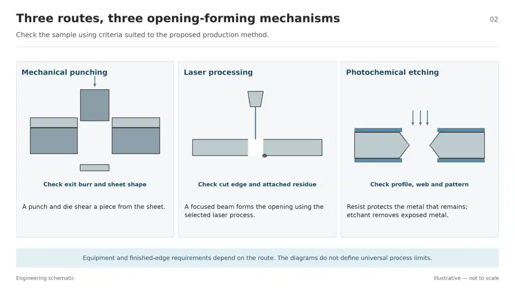
The equipment depends on how the openings are formed. Identify the route in the sample request so the measured result can be traced to the proposed production method.
| Route | How the openings are formed | What to review on the sample |
|---|---|---|
| Mechanical punching | A punch and die shear openings through the sheet | Hole dimensions and position, burrs, and sheet condition. |
| Laser processing | A focused beam cuts or drills the opening, according to the selected process | Hole shape, cut-edge condition, and any attached residue. |
| Photochemical etching | A patterned resist protects the metal that remains while an etchant removes exposed areas | Through-openings, hole-wall profile, minimum web, and pattern consistency. |
Repeated holes may suit punching when suitable tooling and support are available. Thin sheet with a dense or irregular pattern may be a candidate for photo etching. Confirm either route on the proposed geometry. If both are feasible, compare photo etching and mechanical punching using the same finished-part requirements.
Manufacturing Process Step by Step
1. Verify Stock and Prepare the Surface
Check the material identification and thickness against the drawing. Inspect the incoming surface and record the visible face if it affects appearance acceptance. For photo etching, prepare the surface so the photoresist can be applied to clean metal.
Keep a record of the incoming sheet condition. If distortion appears later, that record helps establish when the condition changed.
2. Transfer the Approved Hole Pattern
For punching, prepare the program, locating arrangement, and tooling for the approved revision. Check that the first punched pattern has the required orientation and location.
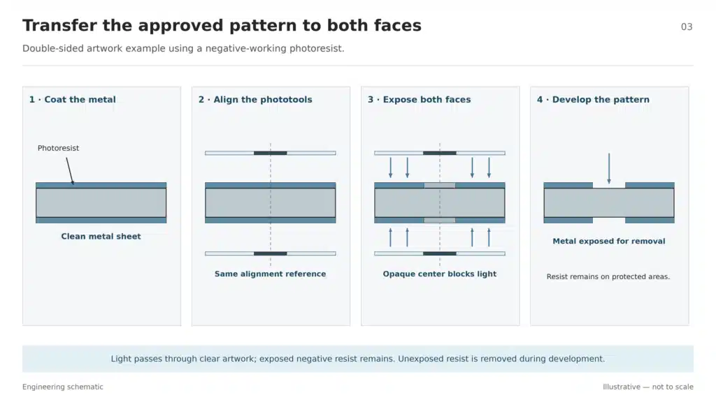
For photo etching, prepare the phototool, apply the resist, and expose and develop the pattern. Where the route uses two-sided artwork, align the two patterns as required. After development, the areas intended for chemical removal are exposed. Inspect the developed pattern before etching.
3. Form the Holes and Check the First Sample
For a punched sample, check hole size, position, pitch, edge condition, and sheet shape. If the sample fails, review the setup and tooling before continuing.
For an etched sample, verify that the required openings pass through the sheet. Measure the critical holes and webs at the specified locations. Since etching can change the hole profile through the thickness, record the measurement surface or section with the result. A dimensional reading needs that location to be interpreted.
4. Remove Process Residues
For punched parts, address burrs and loose remnants according to the approved edge requirements. Mechanical deburring can alter the edge condition, so recheck critical openings afterward.
For etched parts, strip the remaining resist and clean the parts before inspection. Check for residues and restricted openings. Record any additional operation that affects the hole or perimeter.
5. Apply the Specified Finish and Inspect Again
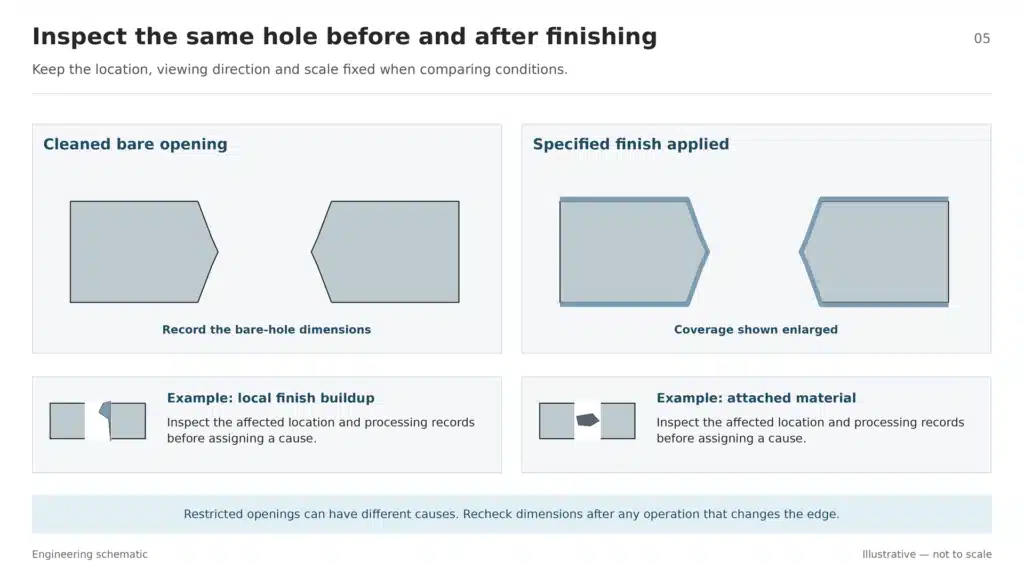
Apply the finish defined on the drawing, then recheck the critical openings, appearance, and part shape. Coating coverage deserves particular attention at sharp edges and irregular geometry. Compare the finished sample with the measurements taken before finishing.
For material and finish selection, use the speaker grille materials and manufacturing guide.
6. Record the Accepted Condition
The inspection record should identify the sample, drawing revision, processing stage, measurement locations, and result. Link approved changes to the next sample. That gives the reviewer a way to distinguish a corrected sample from an earlier revision.
TMNetch case — agreeing on a finished edge. In a TMNetch photo-etching order, a customer asked whether small connection points around the parts were defects. The connections had been retained intentionally. The customer accepted them where they did not affect the finished part’s functional area.
For a micro-hole grille, apply that acceptance principle to the visible perimeter and mating edges. Mark where a separation trace is permitted and check it after release from the sheet. The order provides an example of agreeing on edge acceptance. Project-specific hole and web requirements still belong on the grille drawing.
Inspect the Holes Before and After Finishing
Measure Hole Size, Pitch, Minimum Web, and Flatness
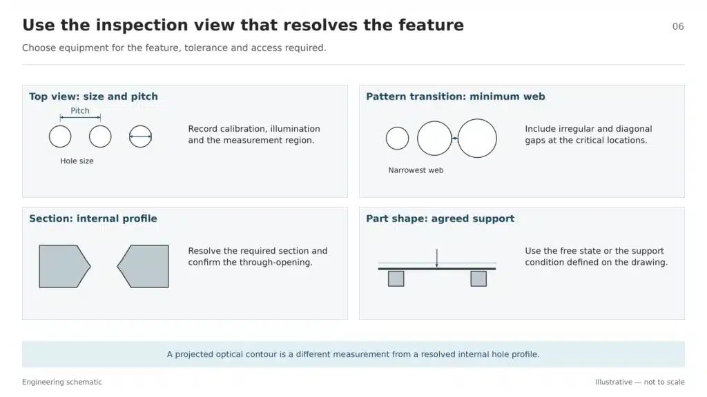
Choose the measuring equipment for the feature, tolerance, and access required. Inspection equipment selection depends on the measurement task. Agree on the measurement locations, sample quantity, and acceptance limits before comparing results.
| Feature | What to check | Condition to record |
|---|---|---|
| Hole size and profile | Required opening dimensions and through-opening condition | Front face, rear face, or specified section, before or after finish |
| Pitch and position | Spacing and location relative to the drawing references | Pattern orientation and measurement region |
| Minimum web | Narrowest metal between the specified openings | Critical locations, including pattern transitions |
| Flatness or part shape | Deviation under the drawing’s specified measurement condition | Free state or the agreed support arrangement |
| Hole-edge condition | Burrs, attached residue, incomplete openings, or finish coverage | Processing stage and any subsequent edge treatment |
For features requiring an internal profile check, agree on a method that can resolve that profile. When using a vision system, include the calibration and illumination conditions in the measurement procedure. Optical measurement performance depends on the system and measurement conditions.
Calculate Measured Open Area in the Agreed Region
Use the approved reference region and divide the measured opening area by that region’s area.
Measured open area (%) = 100 × measured opening area ÷ reference area
For a regular pattern, calculate the value from the measured hole dimensions using the formula for that hole arrangement. For a pattern interrupted by borders or solid zones, define the boundary and sum the actual openings within it.
If the agreed method uses image analysis, record the image scale, lighting, viewing direction, and rule used to classify pixels as open or solid. Label the result as a projected opening-area measurement. Use the same region and procedure before and after finishing. Define any required internal hole dimension separately and select a method that can measure it.
A change in measured open area should lead back to the affected holes. Compare their dimensions and inspect for residue or finish coverage before assigning a cause.
Common Defects and What to Check Next
Locate the stage where the result first changed. Use the observations below to plan checks, then repeat the relevant measurements after a correction.
| Observed condition | What to check next |
|---|---|
| Warping | Compare incoming, processed, separated, and finished states. Review support, handling, and the operation after which the shape changed. |
| Inconsistent hole size or position | Compare the CAD revision, locating references, and first-sample readings. For punching, inspect tooling and clearance. For etching, review artwork, registration, development, and process records. |
| Incomplete or obstructed holes | Establish whether the opening was incomplete after processing or became restricted after cleaning or finishing. Inspect the same locations at each stage. |
| Punching burrs or laser residue | Review the relevant tool or laser setup and the edge-treatment requirement. Recheck dimensions after removal. |
| Etched hole-wall or web variation | Confirm the specified measurement location, then compare hole profiles and minimum webs across the agreed regions. |
Keep a punching slug-removal problem in the tool and setup review. Investigate a restricted opening on the finished grille through the processing and finishing records. Punching tooling and edge control, laser dross, and etched hole-wall geometry each call for checks suited to the route.
Conclusion
A micro-hole grille needs a traceable path from the approved pattern to the finished sample. Lock the material, thickness, hole dimensions, and measurement conditions before processing. Check the first sample, record what changes during finishing, and accept the part against the final drawing requirements.
For a photo-etched grille review, send TMNetch the hole-pattern CAD, alloy and thickness, finish, critical dimensions, and sample quantity. Flag the smallest openings, narrowest webs, and any visible or mating edges. Request a manufacturability review for custom photo-etched speaker grilles.